Smartfield 2120208 Field Sensor User Manual
Smartfield, Inc. Field Sensor Users Manual
Users Manual

BY:
LUBBOCK, TEXAS USA
WWW.SMARTFIELD.COM
LUBBOCK, TEXAS USA
WWW.SMARTFIELD.COM
DESCRIPTION
SmartCrop® is a revolutionary irrigation management system that uses
the plant itself as the sensor. Therefore, we say, “Listen to Your Crop.”
SmartCrop® reads the canopy temperature of the plants every minute
of every day, and then uses this temperature information to determine if
the plant is experiencing water stress.
How does it know? Once SmartCrop® is installed, the system is setup
on our website (www.smartfield.com/data). On the website, the user
inputs information about the crop. Included in this information is the
optimum canopy temperature for the specific crop (we call this the
Stress Temperature). This optimum temperature is determined in a plant
sciences lab. Basically, the researcher measures the activity of certain
enzymes over various temperatures and this lets us know at what tem-
perature the plant grows best.
The actual canopy temperature is then compared to the known optimum
temperature and it is determined if the plant is experiencing any heat
stress. Other measurements are taken to determine if the plant can be
cooled with irrigation. If so, an “irrigate” signal is sent to the grower.
INSTALLATION
The SmartCrop® system is relatively easy to install. The installation
includes positioning the Sensors in the field, positioning and connecting
the Base Station (usually near the irrigation control panel), placement
of the antennas (the cell phone antenna and the antenna for the Field
Sensors), connection of the other sensors to the Base Station, and the
power-up process.
SENSOR INSTALLATION
Before placing the Sensors in the field, the batteries should be installed.
Disconnect the end of the Field Sensor assembly from the tube with a
short counter-clockwise turn. Take out the Field Sensor assembly and lo-
cate the two battery boxes on the circuit board. Install 4 AAA batteries
making certain that the batteries are installed correctly (the negative end
of the battery will contact the coil spring in the battery well.) As soon as
the batteries are installed, the light will blink at the end of the assembly.
Reinstall the Field Sensor assembly into the tube. Once the batteries
are installed, the Sensors will begin running. The light at the end of the
tube will blink occasionally as the Sensor takes environmental readings.
1 6
FCC NOTICE
This equipment has been tested and found to comply with the limits
for a class B digital device, pursuant to part 15 of the FCC Rules. These
limits are designed to provide reasonable protection against harmful
interference in a residential installation. This equipment generates, uses
and can radiate radio frequency energy and if not installed and used
in accordance with the instructions, may cause harmful interference to
radio communications. However, there is no guarantee that interference
will not occur in a particular installation. If this equipment does cause
harmful interference to radio or television reception, which can be deter-
mined by turning the equipment off and on, the user is encouraged to
try to correct the interference by one or more of the following measures:
• Reorient or relocate the receiving antenna.
• Increase the separation between the equipment and receiver.
• Connect the equipment into an outlet on a circuit different from that
to which the receiver is connected.
• Consult the dealer or an experienced radio/TV technician for help.
• It is strongly recommended that the TV be plugged into a separate
wall outlet.
This equipment has been verified to comply with the limits for a class B
computing device, pursuant to FCC Rules. In order to maintain com-
pliance with FCC regulations, shielded cables must be used with this
equipment. Operation with non-approved equipment or unshielded
cables is likely to result in interference to radio and TV reception. The
user is cautioned that changes and modifications made to the equip-
ment without the approval of manufacturer could void the user’s author-
ity to operate this equipment.
5 2
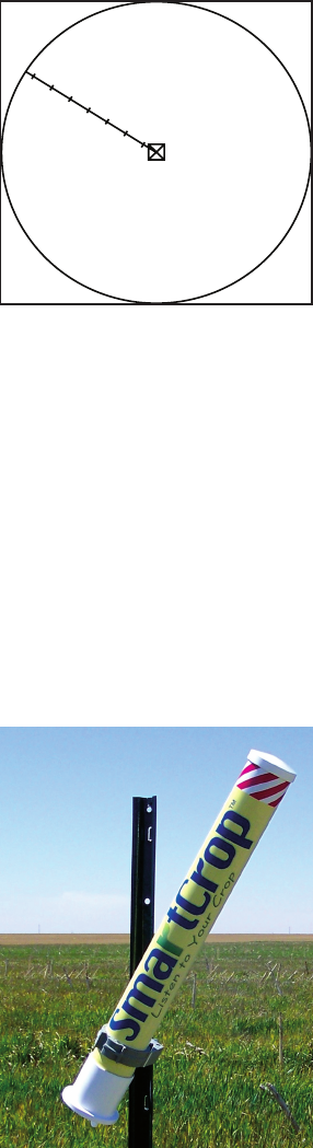
Once the Sensors are operating, they
should be installed in the field. Sen-
sor location in the field is a very critical
step to insure that you receive useful
information regarding the water status
of your crop. If used with a center
pivot, the Sensors should be located
in a straight line proceeding radially
from the base of the center pivot to
the edge of the field (see Figure 1). The
closest Sensor should be 100-300 feet
away from the center of the field and
the furthest Sensor should be 600-1000 feet away from the center of the
field. Additional Sensors can be place between the Sensors at the two ex-
tremes. If used in a field that uses a drip system or is gravity watered, the
sensor placement should be determined based on how the information
will be used. For instance, if various sections of the field can be watered
independently from each other, the additional Field Sensors may be used
to obtain a more precise measurement of water stress in the various sec-
tions of the field. Up to 16 Field Sensors can be used in one system.
The Field Sensor should be placed such that it looks downward at the
crop canopy. Please note the “LEVEL” line on the Field Sensor tube and
install the Field Sensor so that the “LEVEL” line is level with the ground.
The sensor in the end of the Field Sensor tube should be 1-2 feet above
the canopy. The sensor sees a spot on the canopy with a diameter
equal to the distance it is above the
canopy. Take care to arrange the Sen-
sor so that it only sees the crop canopy
and not soil. As the canopy develops,
this will be less of an issue.
The top end of the Sensor contains the
transmitter antenna and it should have
a clear view of the of the system an-
tenna at the Base Controller. If a metal
fence post is used to support the Sen-
sor, the fence post should be placed on
the side of the Sensor away from the
Base Controller. (See Figure 2)
MORE ON ANTENNA PLACEMENT
Antenna placement is extremely critical for maximum performance from
the SmartCrop® system. The Field Sensor antenna collects data from
the sensors in the field. It should be placed so that there are no obstruc-
tions between the antenna and the Sensors. Caution should be taken to
assure that the metal structure of the center pivot base is not inhibiting
the performance of the radio. The system antenna should be placed at
least five feet off the ground using the supplied Antenna Arm as shown
in figure 3. If for some reason the system antenna cannot be placed on
the center pivot structure, then it can be located near the Base Control-
ler in a manner that allows the antenna to be at least five feet off the
ground with a clear line of sight to the Sensors. The Antenna Arm is
designed to locate the system antenna an appropriate distance from the
center pivot tower such that the pivot tower becomes part of the system
antenna thereby maximizing the performance of the antenna. Sensors
with distances of up to 1,000 feet are achievable with correct antenna
placement. If a cell phone modem is part of the system as well, its place-
ment is also critical to the performance of the system.
SYSTEM START-UP
All connections should be checked one more time and then power
should be applied to the Base Station. This is done by first connecting
the on-board battery of the Base Station. The Base Station is shipped
with one of these battery connections not connected. As soon as the
battery is connected, power can be applied to the Base Station from the
two external power sources supplying 12VDC input.
As soon as power is applied to the Base Station the system will begin
operating. It may take up to 15 minutes for all Field Sensors to report.
The Cell Modem may take up to one hour to establish a connection with
the local cell phone tower.
WARRANTY
Smartfield, Inc. warrants the SmartCrop® product for one year from
purchase date. Please see the included warranty for details.
Copyright 2009, Smartfield, Inc.
Sensors
21
Figure 1
Figure 2
3 4
BASE STATION INSTALLATION
The Base Station is generally located near the irrigation control panel.
The Base Station is powered by two incoming 12VDC power sources.
These two separate power sources are used to determine when power
is applied to the irrigation system. Therefore, one power source should
provide power only when the irrigation system is running. This power
source is considered the MAIN power and should be connected as such.
The other power source should provide power continuously and should
be connected as the AUXILLARY power. Do not connect power until all
other connections are made and antennas have been installed.
Find a suitable location for the Base Station and mount it. If it is mount-
ed on the front of a metal electrical panel, the magnets and bracket on
the back of the Base Station can be used to secure it to the panel door.
Once the Base Station is placed in the correct location, proceed with the
following installation steps:
RH POD INSTALLATION
The RH Pod should be located within 8-10 feet of the Base Station in an
area of the field that is similar to the crop environment. If the RH Pod
is located too close to any concrete or bare area of the field, the local
ambient temperature in such an area will be higher than the ambient
temperature in the field. This temperature difference will not provide an
accurate picture of the field condition and should be avoided.
The RH Pod should be mounted on a metal fence post similar to that
used with the Field Sensor. It should be located above the crop canopy,
at a height of at lease 4 feet above the ground.
The RH Pod is supplied with a cable that is similar to a phone cable. This
cable plugs into the RH Pod on the bottom side. The other end of the
cable connects to the circuit board of the Base Station. The cable should
be fastened to the RH Pod bracket to provide protection for the cable.
RAIN GAUGE INSTALLATION
The rain gauge comes installed on the rain gauge bracket. This bracket is
designed to be installed either onto the pivot tower or onto another struc-
ture in the field. The surface of the bracket where the rain gauge sits must
be level for the rain gauge to work correctly. Once the rain gauge bracket
is mounted, use a small level to assure that the bracket is level. The rain
gauge should be approximately 6 to 8 feet above the ground.
The rain gauge has a cable that should be fastened to the bracket and to
various locations along its path to the Base Station so that the cable is pro-
tected. The cable connects to the bottom of the Base Station circuit board.
FIELD SENSOR ANTENNA INSTALLATION
The Field Sensor antenna has a magnetic base. It must have a clear line
of sight to the Field Sensors. Ideally it should be located on the rain
gauge bracket, but it can be located on any metal surface that is the
correct height off the ground. The less optimum the placement of the
Field Sensor antenna, the less range the Field Sensors will have. If the
Base Station is not receiving a signal from some of the Field Sensors,
relocating the Field Sensor antenna to a more optimum location is the
best approach to improve range.
The Field Sensor antenna connects to a small circuit board near the top
right corner of the Base Station.
CELL MODEM ANTENNA INSTALLATION
The Cell Modem antenna also has a magnetic mount. Care must be
taken that the antennas are connected to the proper locations in the Base
Station. The system will not be harmed by incorrect connection, but the
system will not work if the antennas are connected backwards. Place the
Cell Modem antenna on a section of metal, but DO NOT place it on the
rain gauge bracket if the Field Sensor antenna has already been mounted
there. If you know where the closest cell phone tower is, place the antenna
is a location that will provide the best line of sight path with no metal struc-
tures in the way. The cell phone antenna should be place on top of a local
structure, with the antenna pointing vertical. It should NOT be located
between the Sensors and the system antenna. It should be placed away
from the system antenna by a minimum distance of five feet. If the Base
Station is not receiving transmissions from the Sensors, the cellular modem
antenna should be disconnected for a one hour. If the Sensor transmissions
are received by the Base Station then the cellular antenna should be relo-
cated further away from the system antenna and then reconnected.
RAINALERT CONNECTION INSTALLATION
If a RainAlert product was provided with your system, please see the
instructions that came with the RainAlert product for installation to the
irrigation system. When used with a SmartCrop® system, the Hunter
Mini-Klik rain switch is replaced with a connection to the SmartCrop®
Base Station. The Base Station uses information from the rain gauge to
determine when to send a signal to the RainAlert.