Snap One AVM16S11 Audio Matrix Switch-16 AVM-16S1-B User Manual AudioMatrixSwitch UG
Control4 Audio Matrix Switch-16 AVM-16S1-B AudioMatrixSwitch UG
Snap One >
Exhibit 8
Disclaimer
Control4® makes no representations or warranties with respect to the
contents or use of this manual, and specifically disclaims any express or
implied warranties of merchantability or fitness for any particular purpose.
Control4 reserves the right to revise this publication and to make changes
to its content, at any time, without obligation to notify any person or entity
of such revisions or changes.
Control4 makes no representations or warranties with respect to any
Control4 software, and specifically disclaims any express or implied
warranties of merchantability or fitness for any particular purpose. Control4
reserves the right to make changes to any and all parts of Control4
software and hardware, at any time, without any obligation to notify any
person or entity of such changes.
Trademarks
Control4 and the Control4 logo are registered trademarks of Control4
Corporation. Other product and company names mentioned in this
document may be the trademarks or registered trademarks of their
respective owners.
Legal Notice
Gracenote. Music recognition technology and related data are provided by
Gracenote. Gracenote is the industry standard in music recognition
technology and related content delivery. For more information visit
www.gracenote.com.
Copyright
Copyright © 2004-2005 Control4. All rights reserved. No part of this
publication may be reproduced, photocopied, stored on a retrieval system,
or transmitted without the express written consent of the publisher.
Contact Us
Control4 Corporation
11734 S. Election Road, Suite 200
Salt Lake City, UT 84020 USA
http://www.control4.com
Audio Matrix Switch - 16 Installation and User Guide
Part Number: 21-0140 Rev A Draft 9
Hardware Model Number: AVM-16S1-B

i
Contents
Preface About This Guide........................................... 1
Notes, Tips, Cautions, and Warnings .... 1
Additional Resources............................. 2
Chapter 1 Introduction to Audio Matrix Switch ............... 3
Features and Benefits............................ 3
Home Network Requirements................ 4
What’s in the Box................................... 4
About the Audio Matrix Switch ............... 4
Front View with Door Opened........... 4
Back View ......................................... 5
Source Inputs.................................... 5
Audio Outputs ................................... 6
Front Display..................................... 6
LED Lights ........................................ 6
Technical Specifications ................... 7
Chapter 2 Set Up Audio Matrix Switch........................... 9
Plan Your Physical Layout..................... 9
Connect Input and Output Devices...... 11
Connect to the Network and Power ..... 11
Set Up Logical Connections ................ 11
Chapter 3 Use Audio Matrix Switch.............................. 13
View Output Assignments.................... 13
Manage Outputs .................................. 14
Change Output Assignments.......... 14
Configure an Output ....................... 15
Check Signal Status ....................... 17
View Network Settings......................... 17
Set Front Display Preferences ............. 18
Chapter 4 Warranty and Regulatory Compliance......... 21

ii
Warranty .............................................. 21
Limited Hardware Warranty ............ 21
Hardware Warranty Terms ............. 22
Software Agreement ....................... 25
Regulatory Compliance ....................... 26
FCC Interference Statement........... 26
FCC Caution ................................... 27
Canadian EMC Statement .............. 27
UL ................................................... 27
1
PREFACE
About This Guide
Notes, Tips, Cautions, and Warnings
Audio Matrix Switch Installation and User Guide Note, Tip,
Caution, and Warning paragraphs draw your attention to
safe practices and additional information which may help
you avoid losing data or time.
NOTE: These contain notes on related information
about the current topic.
TIP: These provide tips that may save you time or
effort.
CAUTION! These provide specific cautions about
improper use of equipment or failure to follow safety
instructions that may cause bodily injury. DO NOT
IGNORE A CAUTION!
WARNING! These provide specific warnings about
improper use of equipment or failure to follow safety
instructions that may cause data loss or equipment
damage. DO NOT IGNORE A WARNING!

2
Additional Resources
The following resources are available to provide you with
additional support.
`Your authorized Control4 representative or
reseller.
`Control4 Web Site: http://www.Control4.com/

3
CHAPTER 1Introduction to Audio
Matrix Switch
Control4 systems are uniquely configured for every
customer and every site. A popular component among
music lovers is the Control4 Audio Matrix Switch.
This chapter introduces the Control4 Audio Matrix Switch
and its features.
Features and Benefits
`Switches up to 16 input sources to up to 16
simultaneous output zones.
`Front display for adjustments to zone settings and
routing sources. (Adjustments can also be made by
trained installers using Composer Pro software.)
`Adjustable gain, treble, bass, and balance for each
zone.
`Audio sensing on inputs.
`EZ ID, which includes Light Emitting Diodes (LEDs)
on the back to indicate current associations between
Source Inputs and Audio Output. During setup
activities, one “Source” and one “Output” LED will
light to indicate a current association.
`Device chassis is three standard rack units (RU) tall
and rack mountable configuring to EIA 19” rack
standards (5.25” x 17.34” x 14”).
`Communicates with control devices via Ethernet 10/
100 port and ZigBee (a wireless standard for mesh-
networking).
`Backlighting feature turns on with any button push or
Select Dial push and stays lit for a preset time (default
is 30 seconds).
4
Home Network Requirements
In order for Audio Matrix Switch to be managed and
controlled from the Control4 user interfaces, it must
communicate with the system through either a wired
(Ethernet) or wireless (ZigBee) network. If you want to use
an Ethernet connection for Audio Matrix Switch, ensure
that your home network wiring is in place before starting
your system setup.
What’s in the Box
The following items are included in your Control4 Audio
Matrix Switch box.
`Control4 Audio Matrix Switch
`IEC power cord
`This manual
About the Audio Matrix Switch
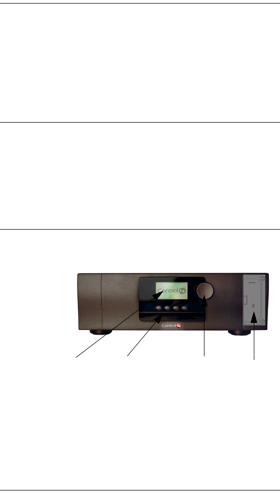
Front View with Door Opened
1. Front Display—For displaying or setting
audio switch settings and navigating system
menus.
2. Buttons—For choosing options or menus
displayed in the front panel user interface.
1234
5
3. Select Dial—For scrolling through and
selecting screen elements or options
displayed in the LCD.
4. Reset Button—For troubleshooting option
behind the door to refresh the system.
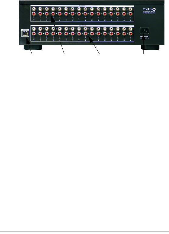
Back View
1. Ethernet—RJ-45 for a 10/100 Mb Ethernet
connection.
2. Audio In (Left-Right pairs) 1-16—RCA jacks
and supporting LED for stereo channel input
for up to 16 stereo analog sources.
3. Audio Out (Left-Right pairs) 1-16—RCA jacks
and supporting LED for stereo channel line
output for up to 16 amplifiers.
4. Power Plug Port—For standard IEC cord
(included). Supports universal AC input (90-
240 ACV 50/60 Hz).
Source Inputs
Each of the 16 signal sensing analog audio inputs (the
RCA style ports) is labeled 1-16 for each individual
source.
123 4

6
Audio Outputs
The system automatically creates generic source names
that are displayed in the front display. To change these
names, you must update your system using the supported
system designing software (such as Composer Pro on a
PC). For more information, refer to the documentation that
shipped with your Control4 controller or contact your
professional installer or reseller.
Front Display
The best method of initially setting up routing for the Audio
Matrix Switch is using the Composer Pro software on a
PC (for trained installers only). But you can also make
adjustments from the front display.
The front display allows you to set or change audio source
routing and change zone settings for volume, bass, treble,
and mute. The display also shows the current source and
zone activity.
LED Lights
This device has EZ ID, which includes Light Emitting
Diodes (LEDs) on the back to indicate current
associations between Source Inputs and Audio Output.
During setup activities, one “Source” and one “Output”
LED will light to indicate a current association.

7
Technical Specifications
Table 1-1. Audio Matrix Switch Technical Specifications
Inputs
# of Channels 16 L/R Stereo Pairs
Input Connectors RCA Jacks
Input Impedance 10 k? typical
Nominal Input Level -10 dBV
Maximum Output Level +4 dBV (to be verified)
Outputs
# of Channels 16 L/R Stereo Pairs
Output Connectors RCA Jacks
Output Impedance 50 ? typical
Nominal Output Level -10 dBV
Maximum Output Level +4 dBV (to be verified)
Zone (Output) Control:
Available Gain Mute (-?) to -44 to +4 dB
Treble -12 to +12 dB, 2 dB steps, ? kHz (-3dB)
High Shelving EQ
Bass -12 to +12 dB, 2 dB steps, ? Hz (-3dB) Low
Shelving EQ
Balance 0 dB mid position; 0 dB on the favored side
0 to -44 dB to Mute (-?) on the unfavored
side
Frequency Response:

8
Any In to Any Out ? Hz to ? kHz, +0/-3 dB
Any In to All Outs ? Hz to ? kHz, +0/-3 dB
Signal-to-Noise Ratio:
Any In to Any Out ? dB typical, 22 Hz to 22 kHz, unweighted
? dB typical, 22 Hz to 22 kHz, A-weighted
Dynamic Range:
Any In to Any Out ? dB typical, 22 Hz to 22 kHz, unweighted
? dB typical, 22 Hz to 22 kHz, A-weighted
THD+Noise:
Any In to Any Out Typically < 0.0x% at 1 kHz, -10 dBV, unity
gain
Typically < 0.0x%, 20 Hz to 20 kHz, -10
dBV, unity gain
Crosstalk:
Inter-channel (any L/R In to
Any L/R Out)
Typically < ? dB at 1 kHz
Typically < ? dB at 1 kHz, 20 Hz to 20 kHz
Intra-channel (any L In to R
Out, or R In to L Out)
Typically < ? dB at 1 kHz
Typically < ? dB at 1 kHz, 20 Hz to 20 kHz
Power:
Voltage 100 VAC to 240 VAC nominal
90 (?) VAC min to 264 VAC max
Frequency 50 to 60 Hz nominal
47 Hz min to 63 Hz max
Table 1-1. Audio Matrix Switch Technical Specifications

9
CHAPTER 2Set Up Audio Matrix
Switch
This device operates as part of the Control4 home
system, which requires physical and logical connections
to function as designed.
The essential setup tasks are:
1.Plan Your Physical Layout
2.Connect Input and Output Devices
3.Connect to the Network and Power
4.Set Up Logical Connections
This chapter describes, in general terms, how to set up
the physical connections required for the Audio Matrix
Switch and all of the devices associated with it. You
should also refer to any device-specific documentation for
additional installation instructions.
To set up the logical connections required, refer to
Control4 Composer Pro User Guide software
documentation.
Plan Your Physical Layout
This section explains physical and logical connections
and can help you plan your physical connections.
Use a worksheet to plan your audio zones: Using the
worksheet provided in Table 2-1 on page 10, identify the
ports you will use for each planned devices and zones.
10
Table 2-1. Audio Matrix Switch Routing Worksheet
RCA
Pair
#
Audio In Sources—RCA
(Left-Right) pairs for stereo
channel input for up to 16
stereo analog sources.
Audio Out Zones—RCA
(Left-Right) pairs for
stereo channel output for
up to 16 output zones.
1.
2.
3.
4.
5.
6.
7.
8.
9.
10.
11.
12.
13.
14.
15.
16.

11
Connect Input and Output Devices
1. Connect the audio source devices (such as CD
changers or players, DVD changers or players, or
tape players) you want included in the system to the
Audio In jacks.
2. Connect amplifiers or amplified speakers as needed
to the Audio Out jacks.
NOTE: If you are not sure which jacks to use, try using
the worksheet provided in Table 2-1 to plan your routes.
Connect to the Network and Power
1. If you are using an Ethernet connection for Audio
Matrix Switch, plug the data cable from the home
network connection into the Audio Matrix Switch RJ-
45 port (labeled “Ethernet”) and the network port in
your wall or at the network hub or switch.
2. Connect the power cord provided to the back of the
Audio Matrix Switch and to the power outlet. Once
the power cord is connected, the Audio Matrix Switch
should power up.
Set Up Logical Connections
Physical and logical connections are required in order to
control, navigate, and use the Audio Matrix Switch as
designed.
Thus far you have set up the physical connections for the
Control4 Audio Matrix Switch. To complete the logical
setup, trained installers must use a PC connected to the
home network with Control4 Composer software installed.
If you are a trained Control4 installer, refer to the Control4
Composer Pro User Guide.

12

13
CHAPTER 3Use Audio Matrix Switch
This chapter introduces the user interface available to
Audio Matrix Switch users and the common system tasks
you can perform with Audio Matrix Switch from the front
display.
NOTE: Following the initial setup, you may never need
to overtly communicate with the Audio Matrix Switch
again. This device simply assists in fulfilling a room-
specific music request. To play music, use a system
navigation device available to your current room to
choose a specific music source or a device. That device
may or may not need to make use of this switch.
View Output Assignments
Once you complete the physical and logical setup tasks,
you can view or change your setup in the Audio Matrix
Switch front display.
When you first power up the Audio Matrix Switch, the
following System Status screen appears momentarily.
----------------------------
Control4
AVM-16S1-B
VER 00.01.02
----------------------------
The System Status screen is then replaced by the
Output to Input screen.

14
Manage Outputs
Change Output Assignments
To change up your “Output to Input” assignments:
1. Ensure your Audio Matrix Switch is powered up and
that the Output to Input screen is displaying in the
front display.
2. On the Output to Input screen, view the current
output-to-input associations.
Output to Input
1- 15- 9- 13-
2- 6-3 10- 14-
3-4 7- 11- 15-
4- 8- 12- 16-
OUT/IN NETWORK DISPLAY
Output to Input
1- 15- 9- 13-
2- 6-3 10- 14-
3- 4 7- 11- 15-
4- 8- 12- 16-

15
The screen consists of 16 output zones and any
assigned input source. When an input source is
highlighted (as Input 1 in this example), the
highlighting indicates that a signal is present.
The buttons on the front panel provide access to
these menu options:
`Out/In: Displays an Output-specific screen. The
most recent screen accessed is displayed by
default, but you can choose to view a different
output’s setting by changing the Output number.
`Network: Displays a Network screen. This is
essentially view-only information.
`Display: Displays the Display Configuration
Screen.
Configure an Output
To view or change output source settings:
1. On the Output to Input screen, press the Out/In
button to view the output settings of the default output
screen (which is the last output screen accessed).
OUT/IN NETWORK DISPLAY
Output 3 Kitchen
Input 4CD
Gain -10
Treble 4
Bass -3
Bal 0
INPUTS EXIT
Output to Input

16
From the output screen, you can: (1) change to
another output screen; (2) change the output settings
on the screen; or (3) toggle to the Input Signal
Sensing screen.
1a. If the Output-specific screen that you want to
view did not display (such as Output 3 in the
previous example), use the Select Dial to
highlight and select the Output number and then
change it.
1b. (Optional) Change settings for the current
output using the supported ranges:
`Input: Displays the number of the
currently assigned input source and any
label that has been given to the input
source (such as “CD” in the sample
provided). You can change this setting to
any of the available input sources.
`Gain: Supported range: Mute and -44 to
+4 dB (default: 0 dB)
`Treble: Supported range: -12 to +12 dB
(default: 0 dB)
`Bass: Supported range: -12 to +12 dB
(default: 0 dB)
`Balance: Supported range: -50 to +50dB
(default: 0 dB)
1c. If you want to toggle to view Input Signal
Sensing information, choose the Inputs button.
1d. If you want to Exit the screen, choose the Exit
button.
2. Rotate the Select Dial to highlight a setting.
3. Press the Select Dial to enter Edit mode.
4. Rotate the dial to change the setting; then press the
dial to Save the new setting and exit the Edit mode
OR, to exit without saving, use the front panel button
indicated to choose the Cancel option.

17
5. Press the Inputs button to go to the Input Signal
Sensing screen, OR press the Exit button to return to
the Output to Input screen.
Check Signal Status
1. From the Output to Input screen, press the Out/In
button, then press the Inputs button to access the
Input Signal Sensing screen.
2. On the Input Signal Sensing screen, view a shaded
circle by the device connection number of any input
device with a signal present.
View Network Settings
To view network settings, access the Network settings
screen. These are view-only fields: MAC Address, DHCP,
IP Address, Subnet Mask, and Default Gateway
Configuration. By default, the system uses DHCP.
Input Signal Sensing
1 5 o _9 o 13 o
2 o 6 o 10 o 14 o
3 o 7 o 11 o 15 o
4 o 8 o 12 o 16 o
OUTPUTS EXIT
Network - Ethernet
MAC 00:00:00:00:00:00

18
Set Front Display Preferences
To set your viewing preferences for the front display:
1. On the Output to Input screen, press the Display
button. The Display Configuration screen displays.
DHCP enabled
IP 255.255.255.255
Mask 0.0.0.0
GWay 0.0.0.0
EXIT
Display Configuration
Brightness: 100
Contrast: 100
Backlight Time: 10
DOWN UP SELECT EXIT
Network - Ethernet

19
2. Use the buttons and/or the Select Dial to choose a
setting to change: Once you press the Select button
(or press the dial), you enter Edit mode.
3. In Edit mode, use the buttons or Select Dial to
change the highlighted setting; then press the OK
button (or press the dial) to save the change and exit
Edit mode.
Brightness: Supported range: 0 to 100
Contrast: Supported range: 0 to 100
Backlight Timeout: Supported settings are:
`OFF (Always Off)
`1 to 90 seconds (default is 30 seconds)
`ON (Always On)
Display Configuration
Brightness: 100
Contrast: 100
Backlight Time: 10
DOWN UP SELECT EXIT

20

21
CHAPTER 4Warranty and Regulatory
Compliance
Warranty
Important: Warranty terms may be different with the country of
purchase; contact your Authorized Control4 Sales and Service
office for detailed product warranty information.
Limited Hardware Warranty
Control4 warrants its Audio Matrix Switch product to be free
from defects in material and workmanship during the warranty
period. If the Audio Matrix Switch proves to be defective in
material or workmanship during the warranty period, Control4
will, at its sole option, repair or replace the product with a like
product. The warranty extends only to products purchased
directly from Control4 Corporation or an Authorized Control4
Dealer.
How long the warranty is effective:
Control4 Audio Matrix Switch are warranted for one (1) year
from the date of the first consumer purchase.
What the warranty does not cover:
`Misuses; unauthorized modification; opening for any reason except
to perform an official upgrade using a proper tools/kit
`Operation or storage outside the environmental specifications for
the product
`In-transit damage and improper maintenance
`Physical damage to the unit, such as a cracked or broken screen or
defect resulting from use of improper software, accessories, media,
supplies, consumables, or such items not designed for use with the
product.

22
Hardware Warranty Terms
READ THESE WARRANTY TERMS CAREFULLY BEFORE
INSTALLING OR USING THE CONTROL4 SYSTEM OR
COMPONENTS. YOUR INSTALLATION AND USE OF THE
SYSTEM OR ANY OF ITS COMPONENTS INDICATES THAT
YOU AGREE TO BE BOUND BY THESE TERMS. IF YOU DO
NOT AGREE TO ALL OF THE TERMS OF THIS WARRANTY,
RETURN THE PRODUCT TO THE PLACE OF PURCHASE
FOR A FULL REFUND.
ONE-YEAR LIMITED WARRANTY
1. WARRANTY
Control4, Corporation. ("Control4") warrants that at the time of
sale the Audio Matrix Switch (the “product”) will be free from
defects in material and manufacture and will conform to
Control4's specifications for the components. Control4 further
warrants that for a period of 12 months after sale the product will
function in accordance with its specification, PROVIDED THAT
it is installed and maintained in accordance with Control4's
instructions and is not subjected to (a) alteration or
unauthorized repairs, (b) misuse or abuse, (c) Acts of God
(including without limitation hurricanes, tornadoes, floods,
earthquakes, or other severe weather or natural phenomena),
or (d) improper storage or handling or other treatment or
installations for which it was not intended. This warranty
extends only to products purchased directly from Control4 or an
Authorized Control4 Dealer.
2. DISCLAIMER OF OTHER WARRANTIES
The preceding warranties are the exclusive and sole express
warranties given by CONTROL4. They supersede any prior,
contrary or additional representations, whether oral or written.
CONTROL4 HEREBY DISCLAIMS AND EXCLUDES ALL
OTHER WARRANTIES-WHETHER EXPRESS, IMPLIED, OR
STATUTORY-INCLUDING ANY ARISING FROM COURSE OF
DEALING OR USAGE OF TRADE, ANY WARRANTY OF

23
MERCHANTABILITY AND ANY WARRANTY OF FITNESS
FOR A PARTICULAR PURPOSE, except that for product
purchased directly by a consumer, any implied warranties are
limited in duration to the term of the express warranties provided
above.
Some states do not allow limitations on how long an implied
warranty lasts, so the above limitation may not apply to you.
3. EXCLUSIVE REMEDY FOR ANY
NONCONFORMITIES
If during the applicable Warranty Period, the product does not
conform to the preceding Warranties, the Owner shall notify
Control4 as provided below, and within a reasonable time
Control4 will provide, at its option, one of the following: (1) a
replacement product for any nonconforming or defective
component (such replacement product may be new or
refurbished to be comparable in function and performance to a
new product) or (2) the price at which Control4 sold the non-
conforming product. In the event of repair or replacement, there
may be a loss of data in the memory of the product for which
warranty service is sought. Control4 will not provide, and will
not be liable for, labor, costs of removal or reinstallation of
product, disposal, freight, taxes, or other incidental charges.
THESE REMEDIES ARE THE EXCLUSIVE AND SOLE
REMEDIES FOR ANY BREACH OF WARRANTY.
For any breach of warranty, the Owner must notify Control4 in
Section 7 below within thirty (30) days after discovering the
nonconformity. The notice must describe the location and
nature of the nonconformity. The owner must give Control4 a
reasonable opportunity to the claimed nonconformity before
undertaking any repairs, removal or replacement. All products
returned to Control4 require a Return Merchandise
Authorization (RMA) number. The RMA number is obtained
from Control4 Customer Support Department. The RMA
number must be clearly marked on the outside of each box. The
RMA is valid for a 30-day period. After the 30-day period, the

24
RMA will be cancelled. Any shipments received not consistent
with the RMA, or after the RMA is cancelled, will be refused.
Control4 is not responsible for products returned without a valid
RMA number. Compliance with the requirements of this
paragraph is a condition to coverage under the Warranty: If
these requirements are not complied with, Control4 will have no
obligation to provide any remedy for any breach of warranty.
4. DISCLAIMER OF INCIDENTAL AND
CONSEQUENTIAL DAMAGES
IN NO EVENT SHALL CONTROL4 BE LIABLE FOR ANY
INCIDENTAL, SPECIAL, INDIRECT OR CONSEQUENTIAL
DAMAGES, WHETHER RESULTING FROM NONDELIVERY
OR FROM THE USE, MISUSE OR INABILITY TO USE THE
PRODUCT OR FROM DEFECTS IN THE PRODUCT OR
FROM CONTROL4'S OWN NEGLIGENCE. This exclusion
applies even if the remedy provided by Control4 fails of its
essential purpose.
Some states do not allow the exclusion or limitation of incidental
or consequential damages, so the above limitation may not
apply to you.
5. APPLICABLE LAW
This Warranty will be interpreted, construed, and enforced in all
respects in accordance with the laws of the State of Utah,
without reference to its choice of law rules. The U.N.
Convention on Contracts for the International Sale of Goods will
not apply to this Warranty.
6. SEVERABILITY
If any provision of this warranty is found to be invalid or
unenforceable, then the remainder shall have full force and
effect, and the invalid provision shall be partially enforced to the
maximum extent permitted by law to effectuate the purpose of
the agreement.

25
7. ADDRESS FOR NOTICES TO CONTROL4
Control4 Corporation
11734 Election Road, Suite 200
Salt Lake City, UT 84020
Fax # 801-523-3199
Telephone # 801-523-3100
This warranty gives you specific legal rights, and you may also
have other rights which vary from State to State.
Software Agreement
The Control4 Audio Matrix Switch contains preinstalled
software. Please read the following Control4 terms before
proceeding:
NOTE: Carefully read this License Agreement and the
Limited Warranty statement before operating the
equipment. The rights to the software are licensed, not
sold. Control4 or its licensors continue to own all
intellectual property rights to the software, and you will
be granted certain rights to use the software upon your
acceptance of this license. Rights in the software are
offered only on the condition that you agree to all terms
and conditions of the License Agreement. Operating
the equipment indicates your acceptance of these
terms and conditions. If you do not agree to the terms
and conditions of the License Agreement, return the
complete package for a full refund now.
Terms that Govern Software Use
You may only use the software as designed on the device on
which it comes pre-installed. You may not reverse, assemble, or
decompile the software.

26
Limited Software Warranty, Liability, and Remedy
Important: This Control4 Software Limited Warranty shall cover
all software that is provided to you, the customer, as part of the
Control4 product, including any operation system software.
The Remedies provided in this document are your sole and
exclusive remedies. In no event shall Control4 be liable for any
direct, indirect, special, incidental, or consequential damages
(including lost profit), whether based on warranty, contract, tort,
or any other legal theory.
In no case shall Control4's liability exceed the purchase price for
the software and/or product. The limitations set forth above will
apply regardless of whether you accept the software.
Regulatory Compliance
This product complies with standards established by the
following regulatory bodies:
Federal Communications Commission (“FCC”)
Canadian Electromagnetic Compatibility (“EMC”)
Underwriters Laboratory (“UL”)
FCC Interference Statement
This equipment has been tested and found to comply with the
limits for a Class B digital device, pursuant to Part 15 of the FCC
Rules. These limits are designed to provide reasonable
protection against harmful interference in a residential
installation. This equipment generates uses and can radiate
radio frequency energy and, if not installed and used in
accordance with the instructions, may cause harmful
interference to radio communications. However, there is no
guarantee that interference will not occur in a particular
installation. If this equipment does cause harmful interference
to radio or television reception, which can be determined by
turning the equipment off and on, the user is encouraged to try
to correct the interference by one of the following measures:

27
`Reorient or relocate the receiving antenna.
`Increase the separation between the equipment and receiver.
`Connect the equipment into an outlet on a circuit different from that
to which the receiver is connected.
`Consult the dealer or an experienced radio/TV technician for help.
FCC Caution
Any changes or modifications not expressly approved by the
party responsible for compliance could void the user's authority
to operate this equipment.
This device complies with Part 15 of the FCC Rules. Operation
is subject to the following two conditions: (1) This device may
not cause harmful interference, and (2) this device must accept
any interference received, including interference that may
cause undesired operation.
Canadian EMC Statement
This Class B digital apparatus complies with Canada ICES-003.
Cet appareil numérique de la classe B est conforme à la norme
NMB-003 du Canada.
UL
This device is NOT yet approved by UL.

28