Snap One AVMMC11 Model AVM-MC1-B Media Controller User Manual MediaController
Control4 Model AVM-MC1-B Media Controller MediaController
Snap One >
Exhibit 8
Disclaimer
Control4® makes no representations or warranties with respect to the
contents or use of this manual, and specifically disclaims any express or
implied warranties of merchantability or fitness for any particular purpose.
Control4 reserves the right to revise this publication and to make changes
to its content, at any time, without obligation to notify any person or entity
of such revisions or changes.
Control4 makes no representations or warranties with respect to any
Control4 software, and specifically disclaims any express or implied
warranties of merchantability or fitness for any particular purpose. Control4
reserves the right to make changes to any and all parts of Control4
software and hardware, at any time, without any obligation to notify any
person or entity of such changes.
Trademarks
Control4 and the Control4 logo are registered trademarks of Control4
Corporation. Other product and company names mentioned in this
document may be the trademarks or registered trademarks of their
respective owners.
Legal Notice
Fraunhofer IIS and Thomson. MPEG Layer-3 audio coding technology
license from Fraunhofer IIS and Thomson. Supply of this product does not
convey a license nor imply any right to distribute content created with this
product in revenue-generating broadcast systems (terrestrial, satellite,
cable, and /or other distribution channels), streaming applications (via
Internet, intranets, and/or other networks), other content distribution
systems (pay-audio or audio-on-demand applications, and the like) or on
physical media (compact discs, digital versatile discs, semiconductor
chips, hard drives, memory cards, and the like).
Gracenote. Music recognition technology and related data are provided by
Gracenote. Gracenote is the industry standard in music recognition
technology and related content delivery. For more information visit
www.gracenote.com.
Copyright
Copyright © 2004-2005 Control4. All rights reserved. No part of this
publication may be reproduced, photocopied, stored on a retrieval system,
or transmitted without the express written consent of the publisher.
Contact Us
Control4 Corporation
11734 S. Election Road, Suite 200
Salt Lake City, UT 84020 USA
http://www.control4.com
Media Controller Installation and User Guide
Part Number: 21-0050 Rev A Draft 7 (in progress)
Hardware Model Number: AVM-MC1-B

i
Contents
Preface About This Guide........................................... 1
Notes, Tips, Cautions, and Warnings .... 1
Additional Resources............................. 2
Chapter 1 Introduction to Media Controller .................... 3
Role in a Control4 System ..................... 3
Features and Benefits............................ 4
Requirements ........................................ 4
Supported Devices ................................ 5
What’s in the Box................................... 5
About the Media Controller .................... 5
Front View with Door Opened........... 7
Back View ......................................... 8
Chapter 2 Set Up the System ...................................... 11
Plan Your Equipment Layout ............... 11
Physical and Logical Connections .. 12
Home Network Requirements......... 12
Sample Setup Diagrams................. 13
Determine Best Video Option ......... 16
Use a Worksheet ............................ 16
Connect to a Monitor or TV.................. 19
Connect to the Network ....................... 20
Connect Devices.................................. 20
Use the Plugable Terminal Blocks.. 20
Connect Wires to a
Configurable Serial Port.................. 21
Add IR Receiver Capabilities to
Remote Locations........................... 22
Set Up IR-Signal Generation to
Control Third-Party Devices............ 23
Use Video Sense Loop to
Add On/Off Sensing........................ 23

ii
Connect AV Devices to One Another ..23
Relocate the WiFi Antenna .................. 24
Set Up Logical Connections ................ 24
Check Setup Using On-Screen Display25
Chapter 3 Use Media Controller................................... 27
User Interfaces .................................... 27
On-Screen Navigator ...................... 27
System Remote Control with LCD .. 28
Media Controller Front Display ....... 29
View or Edit Setup Information ............ 30
Play a CD............................................. 30
Choose a Playlist Option ..................... 31
Understand Future Feature Support.... 32
Chapter 4 Warranty and FCC Information.................... 33
Warranty .............................................. 33
Limited Hardware Warranty ............ 33
Hardware Warranty Terms ............. 34
Software Agreement ....................... 37
FCC Information .................................. 38
FCC Interference Statement........... 38
FCC Caution ................................... 39
1
PREFACE
About This Guide
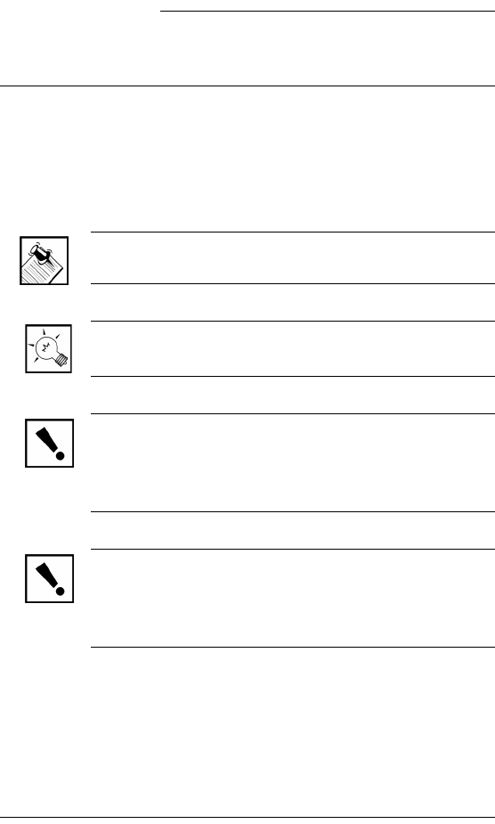
Notes, Tips, Cautions, and Warnings
Media Controller Installation and User Guide Note, Tip,
Caution, and Warning paragraphs draw your attention to
safe practices and additional information which may help
you avoid losing data or time.
NOTE: These contain notes on related information
about the current topic.
TIP: These provide tips that may save you time or
effort.
CAUTION! These provide specific cautions about
improper use of equipment or failure to follow safety
instructions that may cause bodily injury. DO NOT
IGNORE A CAUTION!
WARNING! These provide specific warnings about
improper use of equipment or failure to follow safety
instructions that may cause data loss or equipment
damage. DO NOT IGNORE A WARNING!

2
Additional Resources
The following resources are available to provide you with
additional support.
`Your authorized Control4 representative or
reseller.
`Control4 Web Site: http://www.Control4.com/
3
CHAPTER 1Introduction to Media
Controller
This chapter introduces a Control4 home system and
explains the important role a Media Controller plays in that
system.
Role in a Control4 System
Control4 systems are uniquely configured for every
customer and every site. Your system may be simple or
complex, depending on what you want the system to
control.
An essential component in every Control4 home system
is a controller, such as Media Controller, that acts as the
brain of the system. In addition to providing control
options, Control4 controllers are designed to meet
specific home system needs. Media Controller, for
example, provides extensive media management
services and has a large hard drive for audio storage
(mainly for CDs that you rip to the hard drive).
NOTE: During the importing process, Media Controller
converts CDs to MP3 or WAV format to provide
convenient playback.
Once music has been imported to the Media Controller
hard drive, or other media has been stored in connected
devices, you can use Media Controller to manage your
media collections, play music, or access other stored
media.

4
Features and Benefits
Music Server
`80 GB hard drive
`Multiple input options
`Multi-room audio
`Digital audio streaming
`Gracenote® and Muze®
`Customized playlists
Powerful Home Automation Controller
`Complete control of IR, contact, relay, and serial
connections to control the whole house
`ZigBee mesh networking (802.15.4), WiFi
(802.11b), or Ethernet communication
`Seamless integration (Works with Control4 and
a comprehensive array of third-party
components
Multiple Interfaces — Uses Control4 Touch
Screens, Keypads, System Remote Controls,
or the included On-Screen Navigator.
Requirements
To use Media Controller as designed, meet the following
requirements list:
`Network wiring or wireless network in place
(such as Ethernet or WiFi-802.11b) as needed,
including an Ethernet connection for Media
Controller
`Media Controller (included)
`System Remote Control (included)
`A monitor or TV for on-screen navigation and
control
5
Supported Devices
For any controller purchased through Control4, see the
web site http://www.mycontrol4.com to obtain a list
of what you can add to your system.
NOTE: For a complete list of supported devices and
solutions, see “Products” at http://www.Control4.com
What’s in the Box
The following hardware and software is required and
included in your Control4 Media Controller box.
`Control4 Media Controller with On-Screen Navigator
user interface.
`Control4 System Remote Control (with 4 AAA
Batteries)
`Component video cable
`S-video cable
`Composite video cable
`IEC power cord
`IR emitters (8)
`Stereo RCA cable
`WiFi antenna extension cable
`Control4 On-Screen Navigator User Guide
`This manual
About the Media Controller
Control4 Media Controller is a complete digital music
server and home automation controller that ships with an
on-screen menu for navigation. Media Controller is a key
component in any Control4 system where music storage
and management is required. In addition to the supported

6
audio features, Media Controller also manages lighting,
temperature, and other home automation subsystems.
For audio distribution, it allows you to define pre-amplifier
audio play zones (up to 3 analog and many digital) and
enables digital distributuon. (Note: Digital audio zones
require a network connection—such as Ethernet or
WiFi—to function.)
The Media Controller provides media management. It
also provides control of connected devices. (For detailed
installation instructions, refer to “Set Up the System” on
page 11.)
Once the Media Controller is set up, it will dynamically
maintain the options displayed on any navigation device
associated with it (such as a Mini Touch Screen or a
System Remote Control). These options include room-
specific menus and controls.
7
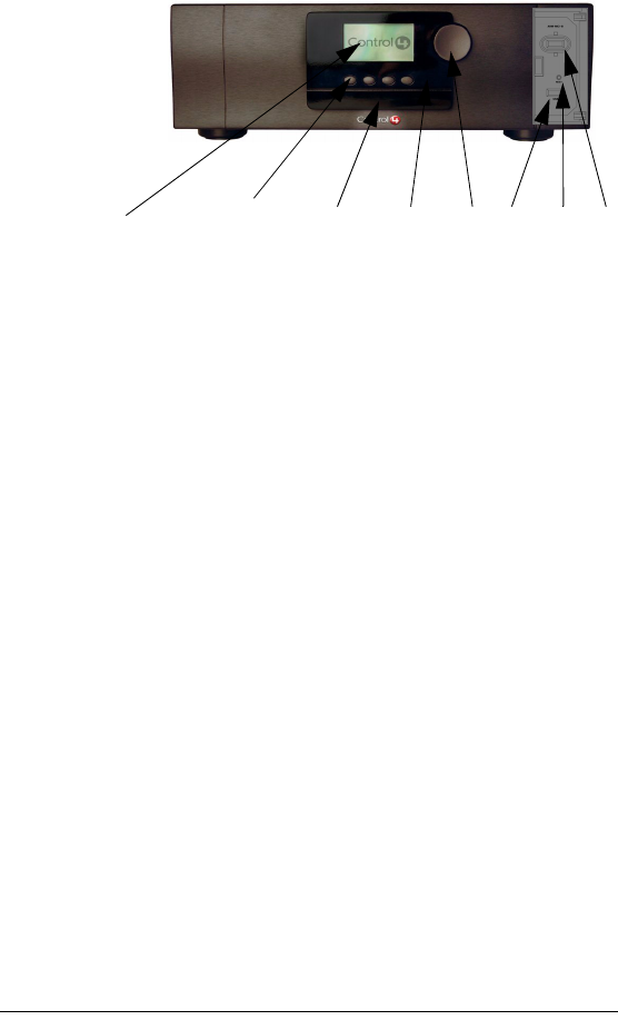
Front View with Door Opened
1. Front display area—For displaying settings,
playlist sections, title sections, media
information, receiver status, and system
menus.
2. Buttons—Provides the user-input method for
options displayed in the front panel user
interface.
3. CD-RW drive—For importing CDs into the
system or playing CDs.
4. IR In window—For reading IR codes or
commands from hand-held devices (such as
third-party remote controls) that are being
set up, or have been set up, to work with
Media Controller.
5. Select Dial—For scrolling through menus
and media lists displayed in the LCD.
6. USB port—For any supported USB device.
7. Reset button—Troubleshooting option to
refresh system.
8. WiFi Antenna Cover and Antenna—To allow
for relocation of WiFi antenna (with included
extender) to improve reception.
1...................2................3............4........5.....6........7.......8
8
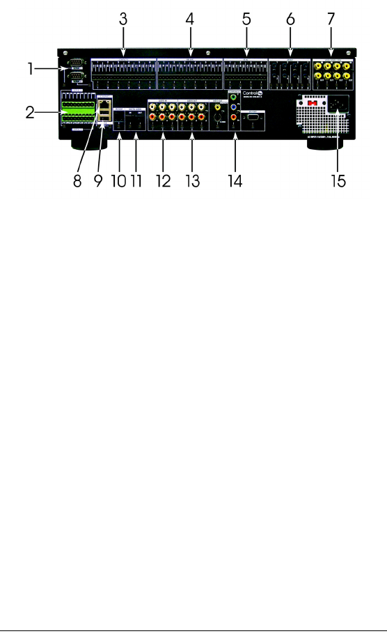
Back View
1. Serial 1-2—Standard serial ports: RS-232
only for up to 2 projectors or other serial I/O
devices, which includes hardware flow
control.
2. Serial 3-4—Configurable serial ports: RS-
232, RS-422, or RS-485 for a projector or
other serial I/O devices.
3. Contacts 1-6—Plugable Terminal Block
connector for up to 6 dry contact closure, or
logic input connections, such as door
switches or motion sensors.
4. Relays 1-6—Plugable Terminal Block
connector for up to 6 normally closed or
normally opened switchable connections,
such as blinds, fireplace, or projector
screens.
5. IR In 1-4—Plugable Terminal Block
connectors provide support for up to 4 hand-
held IR devices, such as remote controllers.

9
6. IR Out 1-8—3.5 mm phone jacks for up to 8
IR sticky emitters that can be placed over IR
readers on media players, TVs, or other
targets to transmit IR signal from Media
Controller to the target.
7. Video Sense Loop In-Out (pairs) 1-4—
Composite port pairs for up to 4 video
sources, such as DVD players or VCRs, that
allow the system to detect the On/Off status
of devices that use the same IR code for both
On and Off commands.
8. Ethernet—RJ-45 for a 10/100 Baset
Ethernet connection.
9. USB—USB port for a card reader or other
USB device.
10. Modem—RJ-11 port for modem to support
caller ID or voice menu system (hardware
foundation for future releases).
11. Digital Audio In/Out—Toslink for Digital
Audio In/Audio Out, like MP3 players.
12. Audio In (Left-Right pairs) 1-3—RCA jack for
stereo channel input for up to 3 stereo analog
sources.
13. Audio Out (Left-Right pairs) 1-3—RCA jack
for stereo channel line output for up to 3
amplifiers.
14. Video Out Options—Composite, S-Video,
Component, and VGA port for displaying
navigation menus on a monitor or TV.
15. Power plug port—For supplied power cord
only.

10

11
CHAPTER 2Set Up the System
This chapter explains how to set up the Control4 home
control system. It includes making hardware connections.
The essential tasks are:
1.Plan Your Equipment Layout
2.Connect to a Monitor or TV
3.Connect to the Network
4.Connect Devices
5.Connect AV Devices to One Another
6.Relocate the WiFi Antenna
7.Set Up Logical Connections
8.Check Setup Using On-Screen Display
Plan Your Equipment Layout
This section explains things you should know or be aware
of when planning your layout:
“Physical and Logical Connections”
“Home Network Requirements”
“Sample Setup Diagrams”
“Determine Best Video Option”
“Use a Worksheet”

12
Physical and Logical Connections
In a Media Controller system, physical and logical
connections are required in order to control, navigate, and
use the system as designed.
This section describes, in general terms, how to set up the
physical connections required for Media Controller and all
of the devices associated with it. You should also refer to
any device-specific documentation for additional
installation instructions.
To set up the logical connections required, refer to
Control4 Composer User Guide software documentation.
Home Network Requirements
Ensure that your home network wiring is in place before
starting your system setup. Consider these networking
issues:
`Media Controller requires an Ethernet connection in
order to use all features as designed. When
connected, Media Controller can access Web-based
media databases (such as Muze and Gracenote) and
can easily access Control4 system updates.
`Media Controller can be used in Ethernet and WiFi
networks, and makes use of ZigBee (wireless mesh
network) 802.15.4 to control lighting and other
ZigBee-enabled products.
`The network wiring required for your system depends
on what you plan to install: Refer to the requirements
outlined in each device’s documentation.
13
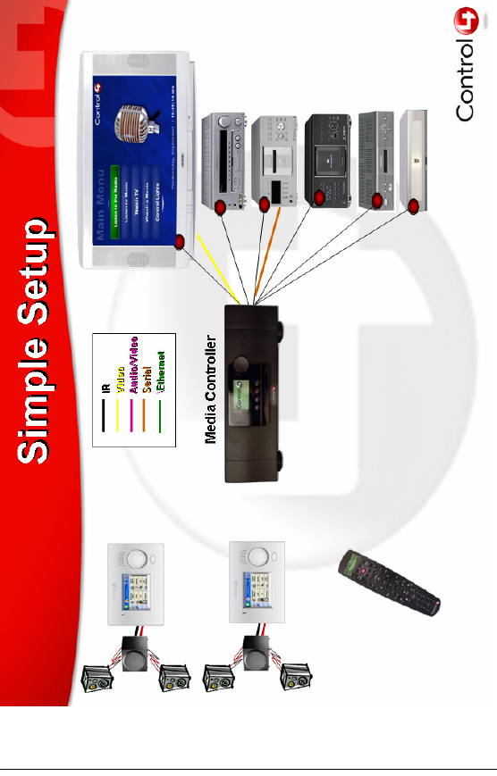
Sample Setup Diagrams
Figure 2-1. Sample Setup: Simple
14
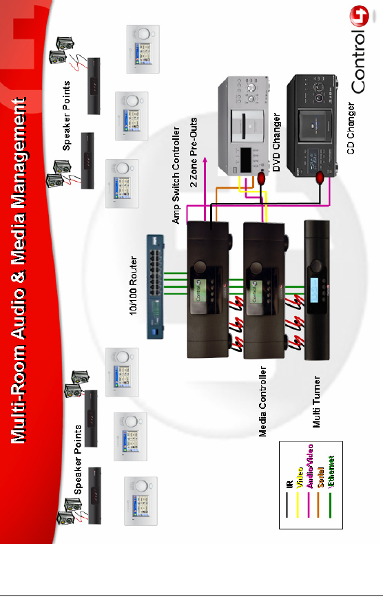
Figure 2-2. Sample Setup: Multi-Room
15
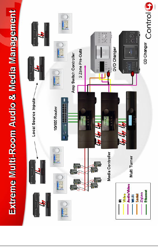
Figure 2-3. Sample Setup: Extreme
16
Determine Best Video Option
There are four Video Out format options to choose from,
but only one option at a time can be used. The system
default is Composite/S-Video.
If you have multiple connection options for a video
component, you need to determine the best connection
available. Table 2-1 provides a list of video connection
options that are ranked according to quality of video
performance:
Use a Worksheet
To use a worksheet to plan your connections:
1. Using Table 2-1, determine what your video output
device will be (such as a monitor or TV) and choose
the best connection option for it.
2. Using the worksheet provided in Table 2-2 on
page 17, identify the Media Controller connection you
will use for all planned connections.
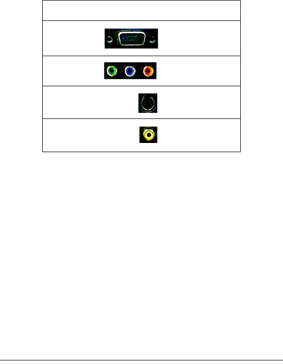
Table 2-1. Video Connection Options Ranked by Quality
Rank Port Description
#1 VGA
#2 Component
#3 S-Video
#4 Composite
17
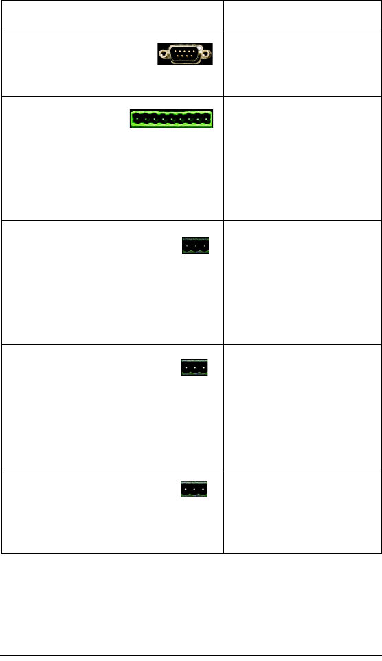
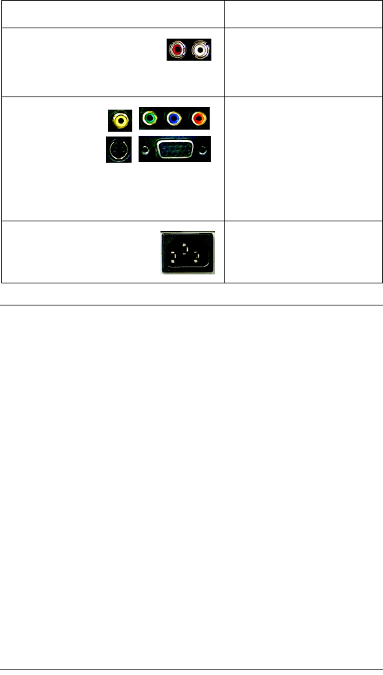
Table 2-2. Media Controller Connection Worksheet
Connection Options and Typical Use Reserved for:
Serial 1-2—Standard
(male) ports: RS-232 only
for up to 2 projectors or
other serial I/O devices.
1.
2.
Serial 3-4—
Configurable ports
that make use of
Plugable Terminal Block connectors: RS-
232, RS-422, or RS-485 for a projector or
other serial I/O devices. Refer to your
device’s installation manual for specific
instructions.
1.
2.
Contacts—Mini Plugable
Terminal Block connectors for up
to 6 sets (+12v, SIG, and GND) of
contact connections, such as door switches
and motion sensors.
1.
2.
3.
4.
5.
6.
Relays—Mini Plugable
Terminal Block connectors for
up to 6 sets (normally closed,
normally opened, and common) of relay
connections, such as blinds, fireplace, or
projector screens.
1.
2.
3.
4.
5.
6.
IR In—Mini Plugable Terminal
Block connectors provide
support for up to 4 IR receivers
that can read infrared signals from remote
controls in remote locations.
1.
2.
3.
4.
18
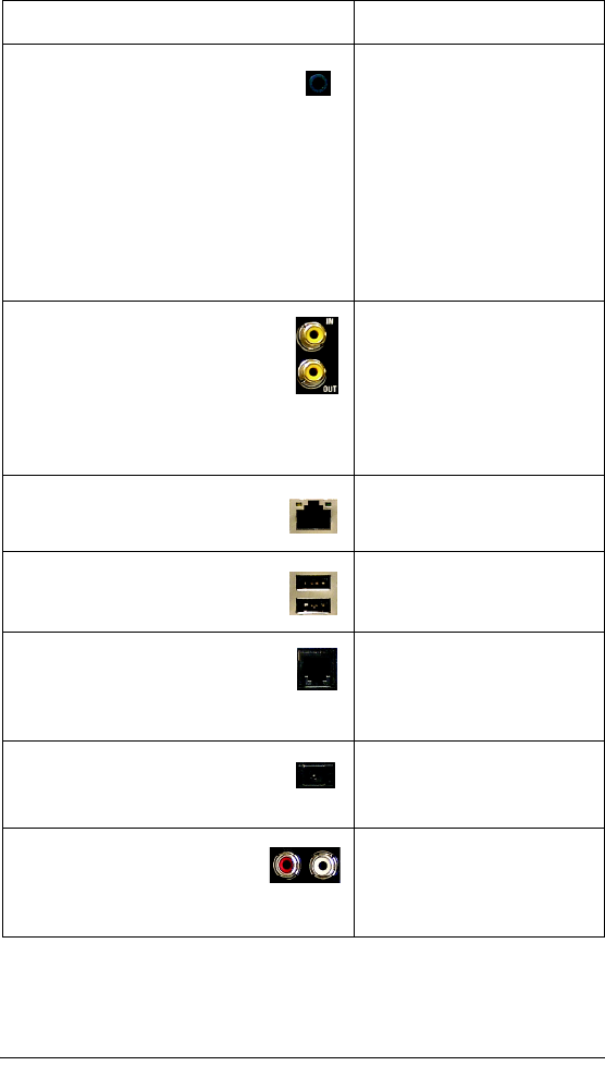
IR Out—3.5 mm jacks for up to 8
IR sticky emitters that can be
placed over IR readers on media
players, TVs, or other targets to transmit
infrared control signals from Media
Controller to the target .
1.
2.
3.
4.
5.
6.
7.
8.
Video Sense Loop—
Composite port In-Out pairs for up
to 4 video sources, such as DVD
players or VCRs, that allow the
system to detect the On/Off status
of devices that use the same IR code for
both On and Off commands.
1.
2.
3.
4.
Ethernet—RJ-45 for a 10/100
Baset Ethernet connection.
1.
USB—Two USB ports for card
readers or other USB devices.
1.
2.
Modem—RJ-11 port for modem
to support caller ID or voice menu
system (hardware foundation for
future releases).
1.
Digital Audio—Toslink for
Digital Audio In/Out, like MP3
players.
In:
Out:
Audio In—RCA (Left-Right)
pairs for stereo channel input
for up to 3 stereo analog
sources.
1.
2.
3.
Connection Options and Typical Use Reserved for:
19
Connect to a Monitor or TV
1. Prepare to connect Media Controller by ensuring you
have all of the required hardware and software and
any optional component you want to connect, as
outlined in the previous chapter.
2. Connect Media Controller to a monitor or TV.
2a. Ensure the monitor or TV is unplugged from
the power supply.
2b. Connect the monitor or TV to the back of
Media Controller using the VGA,
Component, S-Video or Composite
connection port. (Refer to Table 2-1 on
page 16.)
2c. Plug Media Controller power cord
(provided) and the monitor or TV power
cord into electrical outlets.
Audio Out—RCA (Left-
Right) pairs for stereo channel
output for up to 3 stereo line-
level outputs.
1.
2.
3.
Video Out—
Choose one
option
(Composite, S-
Video,
Component, or VGA) for displaying
navigation menus and media databases on
a monitor or TV (not for viewing movies).
1.
Power—AC Input (IEC
Power Cord)
Included power cord only
Connection Options and Typical Use Reserved for:
20
Connect to the Network
If you are using an Ethernet connection for Media
Controller, plug the data cable from the home network
connection into the Media Controller RJ-45 port (labeled
“Ethernet”) and the network port in your wall or at the
network hub or switch.
Connect Devices
For the hardware you want included in the system,
connect the applicable devices to Media Controller
(including such things as contact sensors, relays, IR
sensors, and some AV equipment, such as an audio
amplifier or switch). If you are not sure which connection
port to use, refer to “Plan Your Equipment Layout” on
page 11. The following sections contain additional
information you may find helpful:
`“Use the Plugable Terminal Blocks”
`“Connect Wires to a Configurable Serial Port”
`“Add IR Receiver Capabilities to Remote Locations”
`“Set Up IR-Signal Generation to Control Third-Party
Devices”
`“Use Video Sense Loop to Add On/Off Sensing”
Use the Plugable Terminal Blocks
Many Media Controller connections, including Serial Ports
3 and 4, Contacts and Relays, make use of a Plugable
Terminal Block—a removable plastic part with locking
latches for individual wires. Media Controller ships with
one plugable terminal block for every applicable port.
NOTE: When you connect dry contact closure devices,
such as door switches, connect the switch between +12v
and SIG.

21
To connect a device to a Plugable Terminal Block:
1. Insert one of the wires required for your device into
the appropriate opening in the Plugable Terminal
Block you reserved for that device (refer to Table 2-2
on page 17). For example, if you were adding an IR
motion sensor, you would connect the motion sensor
power input to +12v, its ground connector GND, and
its output to SIG.
2. Lower the opening’s latch until it locks the wire in
place.
3. Repeat Steps 1-2 for all wires required for your
device.
Connect Wires to a
Configurable Serial Port
Media Controller provides four serial ports: Two that use
standard male DB9 connector and two that are
configurable as RS-232, RS-422, or RS-485 and provide
hardware handshake.
Wiring to one of the configurable ports depends on the
wiring requirements of the device you are connecting.
Refer to your device’s documentation and the following
tables to determine how to wire the port. Refer also to
“Use the Plugable Terminal Blocks” on page 20.
Table 2-3. Serial Port Configuration Options
Connector Type Transmit Receive Ground
RS-232 TX RX GND
RS-422 TX+TX- RX+ RX-
RS-485 TX+ RX+ TX- RX-

22
Table 2-4. Configure RS-232 (Standard Serial Cable) for
Configurable Port
Add IR Receiver Capabilities to Remote Locations
To add a remote infrared (IR) receiver to your Media
Controller:
1. Place your IR receiver “In” end at the remote location
needed.
2. Discreetly run the wires from the remote location to
the back of the Media Controller.
3. Connect the IR receiver wires (generally Power,
Signal, and Ground) to one of the Media Controller IR
In connectors (a Plugable Terminal Block connector).
Refer to the IR receiver’s documentation to
determine wiring needed and see “Use the Plugable
Terminal Blocks” on page 20.
Function DB9 Pin Phoenix
Connector
Transmit 2 TX (1)
Receive 3 RX (3)
Ground 5 GND (9)

23
Set Up IR-Signal Generation to
Control Third-Party Devices
Your system may contain third-party products that ship
with IR (infrared) remote controls. To provide a way for
Media Controller to control a device that only recognizes
IR commands, complete the following setup.
1. Plug the 3.5 mm connector end of one of the 8 IR
stick-on emitters provided into an IR Out port on the
Media Controller.
2. Place the stick-on emitter end over the IR receiver on
the media player, TV, or other target device to
transmit IR signals from the Media Controller to the
target.
You can now use the System Remote Control to control
the connected IR-controlled device.
Use Video Sense Loop to
Add On/Off Sensing
If you need to add On/Off sensing capabilities to a device
(such as a TV or DVD player), connect one of the device’s
composite Video Out ports to a Media Controller Video
Sense Loop In port. Then use the companion Video
Sense Loop Out port for the device’s video out as needed.
Connect AV Devices to One Another
1. Connect Audio components to one another. For
example:
`If you connected a Control4 Audio Matrix Switch
(or a third-party audio switch) to Media
Controller, then connect all amplifiers and other
A/V equipment to the audio switch.
`If you connected a Control4 Multi Channel
Amplifier (or a third-party amplifier) to Media
Controller, then connect all applicable speakers
to the amp.

24
2. Connect Video devices to one another. For example,
if you intend to play DVDs directly from a DVD player
to your TV, connect the DVD player’s Video Out to the
TV’s Video In.
Relocate the WiFi Antenna
The WiFi antenna is installed behind the Media Controller
front panel door. If Media Controller is installed in an all-
metal rack with front metal doors, then WiFi may not
function very well. In this case, the WiFi antenna may be
relocated outside of the rack.To relocate it:
1. Remove the WiFi antenna from the front panel
position:
1a. Open the front panel door, then remove the
WiFi antenna cover by pinching it at the top
and bottom.
1b. Unplug the WiFi antenna from the front
USB port.
2. Using the WiFi extension USB cable provided,
connect the WiFi antenna to the back panel USB
port.
3. Adjust the WiFi antenna position outside of the metal
rack.
Set Up Logical Connections
Thus far you have set up the physical connections for the
Control4 home system. But the setup is not complete until
you set up the system’s logical connections as well. To
complete the logical setup, use a PC connected to the
home network with Control4 Composer software installed.
For instructions, refer to the Control4 Composer User
Guide.

25
Check Setup Using On-Screen Display
Once you have completed the physical and logical setup
tasks, you should be able to access the On-Screen
Navigator home page on the monitor or TV. Complete the
following steps to check the setup.
1. On the remote control, press to display the On-
Screen Navigator home page (or main menu) on the
monitor or TV. (If screen does not display, check the
power to the monitor.)
2. Press any subsystem button to jump to that
subsystem’s menu, then press to return to the
home page.
For example, press the Radio button on the Remote
Control and the on-scren display shows the Radio
menu. Then, press to return to the home page.

26

27
CHAPTER 3Use Media Controller
This chapter introduces user interfaces available to Media
Controller users and the common system tasks you can
perform with Media Controller.
User Interfaces
The following user interfaces are available by default with
Media Controller:
On-Screen Navigator
System Remote Control with LCD
Media Controller Front Display
Additional user interfaces ship with navigaton devices that
are sold separately and are described in the
documentation that ships with the device.
On-Screen Navigator
Media Controller provides an on-screen menu called
Control4 On-Screen Navigator. Once Media Controller is
setup and a monitor or TV is connected to it, you can
press the button on the remote control to access the
On-Screen Navigator home page at any time.
The home page provides access to the following
subsystems:
`Radio: Allows you to browse all stations available,
your favorite stations, or choose a source (AM, FM.
XM, NET, or Cable).
`Music: Displays playback options by song title,
album title, artist, or genre. Also provides Record
Music on a sub-menu, that displays recording options
and steps you through the process.
`TV: Choose to browse all or pick a category, then
choose a channel. If the TV or other source is on, it
should respond to the request.
28
`Videos: Displays movie-playing options when a
controlled DVD player or changer has been included
in the system.
`Comfort: Allow you to control all comfort related
devices, such as a thermostat, radiant heating, fans,
curtains and blinds, and a fireplace. It can also display
the current indoor temperature.
`Lights: Provides a list of rooms from which you
choose to view controls for the lights and lighting
scenes for that room.
`House: Diplays control options for miscellaneous
home control features, with an emphasis on security
(such as door locks, motion sensors, contact sensors,
and cameras). But may also control sprinklers, and
communication information (like Caller ID).
`Info: Displays your personal profile and options for
this navigator (the selected controller, room, and
appearance and other options available). You might
also find organization (calendar) information and tools
(maybe wizards) for managing devices and events.
`Location: Set the room location and associated
controller for this navigator option. [Does this differ
from “View or Change Info”?].
For detailed information about using On-Screen
Navigator, refer to the On-Screen Navigator User Guide.
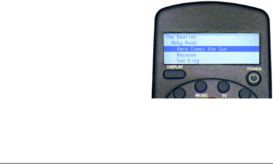
System Remote Control with LCD
The Control4 System
Remote Control that
ships with Media
Controller includes a
liquid crystal display
(LCD), in addition to a
variety of buttons for
accessing and
controlling system
components and
media. The information that displays on the remote
control LCD depends on the action you choose with the

29
remote control buttons and/or with another system
navigation device.
For detailed information on the remote control, refer to the
System Remote Control User Guide included with your
Control4 remote control.
Media Controller Front Display
The information that displays on the Media Controller front
display depends on the action you choose with the Media
Controller buttons or with some other system navigation
device.
-----------------------------------------------------
..............Control4..................
...Saturday, Nov. 13 .....00:06:30...
..................................................
EJECT..............................SETUP
-----------------------------------------------------
When you load a CD into the tray, the LCD view changes:
-----------------------------------------------------
.....Album..................Rip CDs.....
.....Artist...................Play CDs....
.....Tracks.................Playlist.......
................................CD Info.......
-----------------------------------------------------
For detailed information about using the Media Controller
front panel user interface for specific tasks, refer to these
remaining sections in this document:
“View or Edit Setup Information” on page 30
“Play a CD” on page 30
“Choose a Playlist Option” on page 31
“Understand Future Feature Support” on
page 32

30
View or Edit Setup Information
To view or edit Media Controller setup information:
1. On the Media Controller front panel, press the
SETUP button. The System Configuration screen is
displayed:
-----------------------------------------------------
..............Host Setup......................
..............DHCP Client.....................
.....IP....10.11.11.??? (your IP)..........
.....MSK....255.255.0.0....................
.....MAC 00:0F:FF:00:01:30.............
EDIT.................................CANCEL
-----------------------------------------------------
2. If you need to change the setup, press the EDIT
button. The Network Setup screen is displayed:
-----------------------------------------------------
.......1. Host Setme......................
.......2. DHCP Client.....................
.......3. DHCP Server.....................
.......4. Static IP............................
.....MAC 00:0F:FF:00:01:30...........
.....................................CANCEL
-----------------------------------------------------
3. To exit Setup, press the CANCEL button.
Play a CD
To play a CD from Media Controller:
1. On the Media Controller front panel, open the CD tray
(press the EJECT button), load a CD, and close the
CD tray. The LCD should now display the CD menu.
2. Using the dial, choose Play CDs (turn the dial to
highlight Play CDs, then press the dial).

31
3. When you are finished playing the CD, open the CD
tray, remove the CD, and close the CD tray.
Choose a Playlist Option
1. On the Media Controller front panel, open the CD tray
(press the EJECT button), load a CD, and close the
CD tray. The LCD should now display the CD menu.
2. Using the dial, choose Playlist (turn the dial to
highlight Playlist, then press the dial). The Playlist
options display:
Create a new playlist
Load a CD to a new or existing playlist
Select a playlist to be played
3. To create a new playlist:
3a. Choose Create a new playlist and then
follow the screen prompts.
3b. When you are finished with the CD, open
the CD tray, remove the CD, and close the
CD tray.
4. To load a CD to a new or existing playlist
4a. Choose Load a CD to a new or existing
playlist and then follow the screen prompts.
4b. When you are finished with the CD, open
the CD tray, remove the CD, and close the
CD tray.
5. To select a playlist to be played:
5a. Choose Select a playlist to be played and
then follow the screen prompts.
5b. When you are finished with the CD, open
the CD tray, remove the CD, and close the
CD tray.

32
Understand Future Feature Support
Media Controller has been prepared to support future
features. As features are added and software updates
become available, you will be able to use your box for
such things as System Navigation, Caller ID, and Media
Management.
For example, the buttons on the front panel will some day
provide navigation options that are currently available
only in the full-featured navigation methods (such as
Wireless Touch Screen or On-Screen Navigator).

33
CHAPTER 4Warranty and FCC
Information
Warranty
Important: Warranty terms may be different with the country of
purchase; contact your Authorized Control4 Sales and Service
office for detailed product warranty information.
Limited Hardware Warranty
Control4 warrants its Media Controller product to be free from
defects in material and workmanship during the warranty
period. If the Media Controller proves to be defective in material
or workmanship during the warranty period, Control4 will, at its
sole option, repair or replace the product with a like product. The
warranty extends only to products purchased directly from
Control4 Corporation or an Authorized Control4 Dealer.
How long the warranty is effective:
Control4 Media Controller are warranted for one (1) year from
the date of the first consumer purchase.
What the warranty does not cover:
`Misuses; unauthorized modification; opening for any reason except
to perform an official upgrade using an proper tools/kit
`Operation or storage outside the environmental specifications for
the product
`The battery, or damage caused by this battery
`In-transit damage and improper maintenance
`Physical damage to the unit, such as a cracked or broken screen or
defect resulting from use of improper software, accessories, media,
supplies, consumables, or such items not designed for use with the
product.

34
Hardware Warranty Terms
READ THESE WARRANTY TERMS CAREFULLY BEFORE
INSTALLING OR USING THE CONTROL4 SYSTEM OR
COMPONENTS. YOUR INSTALLATION AND USE OF THE
SYSTEM OR ANY OF ITS COMPONENTS INDICATES THAT
YOU AGREE TO BE BOUND BY THESE TERMS. IF YOU DO
NOT AGREE TO ALL OF THE TERMS OF THIS WARRANTY,
RETURN THE PRODUCT TO THE PLACE OF PURCHASE
FOR A FULL REFUND.
ONE-YEAR LIMITED WARRANTY
1. WARRANTY
Control4, Corporation. ("Control4") warrants that at the time of
sale the Media Controller (the “product”) will be free from
defects in material and manufacture and will conform to
Control4's specifications for the components. Control4 further
warrants that for a period of 12 months after sale the product will
function in accordance with its specification, PROVIDED THAT
it is installed and maintained in accordance with Control4's
instructions and is not subjected to (a) alteration or
unauthorized repairs, (b) misuse or abuse, (c) Acts of God
(including without limitation hurricanes, tornadoes, floods,
earthquakes, or other severe weather or natural phenomena),
or (d) improper storage or handling or other treatment or
installations for which it was not intended. This warranty
extends only to products purchased directly from Control4 or an
Authorized Control4 Dealer.
2. DISCLAIMER OF OTHER WARRANTIES
The preceding warranties are the exclusive and sole express
warranties given by CONTROL4. They supersede any prior,
contrary or additional representations, whether oral or written.
CONTROL4 HEREBY DISCLAIMS AND EXCLUDES ALL
OTHER WARRANTIES-WHETHER EXPRESS, IMPLIED, OR
STATUTORY-INCLUDING ANY ARISING FROM COURSE OF
DEALING OR USAGE OF TRADE, ANY WARRANTY OF

35
MERCHANTABILITY AND ANY WARRANTY OF FITNESS
FOR A PARTICULAR PURPOSE, except that for product
purchased directly by a consumer, any implied warranties are
limited in duration to the term of the express warranties provided
above.
Some states do not allow limitations on how long an implied
warranty lasts, so the above limitation may not apply to you.
3. EXCLUSIVE REMEDY FOR ANY
NONCONFORMITIES
If during the applicable Warranty Period, the product does not
conform to the preceding Warranties, the Owner shall notify
Control4 as provided below, and within a reasonable time
Control4 will provide, at its option, one of the following: (1) a
replacement product for any nonconforming or defective
component (such replacement product may be new or
refurbished to be comparable in function and performance to a
new product) or (2) the price at which Control4 sold the non-
conforming product. In the event of repair or replacement, there
may be a loss of data in the memory of the product for which
warranty service is sought. Control4 will not provide, and will
not be liable for, labor, costs of removal or reinstallation of
product, disposal, freight, taxes, or other incidental charges.
THESE REMEDIES ARE THE EXCLUSIVE AND SOLE
REMEDIES FOR ANY BREACH OF WARRANTY.
For any breach of warranty, the Owner must notify Control4 in
Section 7 below within thirty (30) days after discovering the
nonconformity. The notice must describe the location and
nature of the nonconformity. The owner must give Control4 a
reasonable opportunity to the claimed nonconformity before
undertaking any repairs, removal or replacement. All products
returned to Control4 require a Return Merchandise
Authorization (RMA) number. The RMA number is obtained
from Control4 Customer Support Department. The RMA
number must be clearly marked on the outside of each box. The
RMA is valid for a 30-day period. After the 30-day period, the

36
RMA will be cancelled. Any shipments received not consistent
with the RMA, or after the RMA is cancelled, will be refused.
Control4 is not responsible for products returned without a valid
RMA number. Compliance with the requirements of this
paragraph is a condition to coverage under the Warranty: If
these requirements are not complied with, Control4 will have no
obligation to provide any remedy for any breach of warranty.
4. DISCLAIMER OF INCIDENTAL AND
CONSEQUENTIAL DAMAGES
IN NO EVENT SHALL CONTROL4 BE LIABLE FOR ANY
INCIDENTAL, SPECIAL, INDIRECT OR CONSEQUENTIAL
DAMAGES, WHETHER RESULTING FROM NONDELIVERY
OR FROM THE USE, MISUSE OR INABILITY TO USE THE
PRODUCT OR FROM DEFECTS IN THE PRODUCT OR
FROM CONTROL4'S OWN NEGLIGENCE. This exclusion
applies even if the remedy provided by Control4 fails of its
essential purpose.
Some states do not allow the exclusion or limitation of incidental
or consequential damages, so the above limitation may not
apply to you.
5. APPLICABLE LAW
This Warranty will be interpreted, construed, and enforced in all
respects in accordance with the laws of the State of Utah,
without reference to its choice of law rules. The U.N.
Convention on Contracts for the International Sale of Goods will
not apply to this Warranty.
6. SEVERABILITY
If any provision of this warranty is found to be invalid or
unenforceable, then the remainder shall have full force and
effect, and the invalid provision shall be partially enforced to the
maximum extent permitted by law to effectuate the purpose of
the agreement.
37
7. ADDRESS FOR NOTICES TO CONTROL4
Control4 Corporation
11734 Election Road, Suite 200
Salt Lake City, UT 84020
Fax # 801-523-3199
Telephone # 801-523-3100
This warranty gives you specific legal rights, and you may also
have other rights which vary from State to State.
Software Agreement
The Control4 Media Controller contains preinstalled software.
Please read the following Control4 terms before proceeding:
NOTE: Carefully read this License Agreement and the
Limited Warranty statement before operating the
equipment. The rights to the software are licensed, not
sold. Control4 or its licensors continue to own all
intellectual property rights to the software, and you will
be granted certain rights to use the software upon your
acceptance of this license. Rights in the software are
offered only on the condition that you agree to all terms
and conditions of the License Agreement. Operating
the equipment indicates your acceptance of these
terms and conditions. If you do not agree to the terms
and conditions of the License Agreement, return the
complete package for a full refund now.
Terms that Govern Software Use
You may only use the software as designed on the device on
which it comes pre-installed. You may not reverse, assemble, or
decompile the software.

38
Limited Software Warranty, Liability, and Remedy
Important: This Control4 Software Limited Warranty shall cover
all software that is provided to you, the customer, as part of the
Control4 product, including any operation system software.
The Remedies provided in this document are your sole and
exclusive remedies. In no event shall Control4 be liable for any
direct, indirect, special, incidental, or consequential damages
(including lost profit), whether based on warranty, contract, tort,
or any other legal theory.
In no case shall Control4's liability exceed the purchase price for
the software and/or product. The limitations set forth above will
apply regardless of whether you accept the software.
FCC Information
FCC Interference Statement
This equipment has been tested and found to comply with the
limits for a Class B digital device, pursuant to Part 15 of the FCC
Rules. These limits are designed to provide reasonable
protection against harmful interference in a residential
installation. This equipment generates uses and can radiate
radio frequency energy and, if not installed and used in
accordance with the instructions, may cause harmful
interference to radio communications. However, there is no
guarantee that interference will not occur in a particular
installation. If this equipment does cause harmful interference
to radio or television reception, which can be determined by
turning the equipment off and on, the user is encouraged to try
to correct the interference by one of the following measures:
`Reorient or relocate the receiving antenna.
`Increase the separation between the equipment and receiver.
`Connect the equipment into an outlet on a circuit different from that
to which the receiver is connected.
`Consult the dealer or an experienced radio/TV technician for help.

39
FCC Caution
Any changes or modifications not expressly approved by the
party responsible for compliance could void the user's authority
to operate this equipment.
This device complies with Part 15 of the FCC Rules. Operation
is subject to the following two conditions: (1) This device may
not cause harmful interference, and (2) this device must accept
any interference received, including interference that may
cause undesired operation.

40