Snap One C4AM20 Switchable Appliance Module User Manual SwitchableApplianceModule 15 20 Amp 120VAC
Control4 Switchable Appliance Module SwitchableApplianceModule 15 20 Amp 120VAC
Snap One >
Exhibit 8
15-Amp or 20-Amp
120VAC Switchable
Appliance Module
Installation Guide
Supported Model
#C4-AM15-120-Z-B 15-Amp Appliance Switch
#C4-AM20-120-Z-B 20-Amp Appliance Switch
Specifications
Description
The 20-Amp Appliance Switch is a device that helps you to limit use of a high
power-consuming device, such as a room air conditioner, refrigerator,
freezer, or television set during high-peak (most expensive) power
conditions.
The Appliance Switch is controlled by a Control4 home automation system
using an industry standard radio communications connection (802.15.4, also
known as ZigBeeTM).
The Appliance Switch works with your Control4 home automation system
and utility companies to provide you with rate information and rules that you
can adjust to help minimize the power consumption of your key appliances
during high rate periods. The Appliance Switch switches LED colors to
indicate current status and power consumption (as described in Table 5 on
page 2). This information is also sent to the Home Controller as a system
event. System events can be used in programming either to notify home
owners of rate changes or to turn on or off an appliance.
Features
This appliance switch offers the following features:
•Controls a single 120VAC 15-Amp or 20-Amp appliance (depending
on model of appliance switch) with not more than a 1 HP Motor.
•Signals through LEDs on the Appliance Switch what conservation
level or power rate class you are currently in.
•Signals to you how much power your appliance is comsuming by
changing colors on an LED.
•Communicates with a Control4 home automation system.
•Configurable through the Control4 home automation system.
•Provides voltage, current, wattage, power factor, and total power
consumption through the Control4 home automation system.
Important Warnings and Information
WARNING! The Switchable Appliance Module is rated for a combined load as
listed in the table above; do not plug in devices that exceed these ratings, either
alone or in combination.
WARNING! Improper use or installation can cause SERIOUS INJURY,
DEATH, or LOSS/DAMAGE OF PROPERTY.
WARNING! Install in accordance with all national, state, and local electrical
codes.
WARNING! This product generates heat. The room must have adequate
ventilation or the ability to dissipate heat effectively.
WARNING! This product must be grounded in accordance with the National
Electrical Code (NEC) requirements.
WARNING! Use this product only in dry locations.
CAUTION! This product is for residential use only.
IMPORTANT! Using this product in a manner other than outlined in this
document voids your warranty. Further, Control4 is not liable for any damage
incurred because of the misuse of this product. See “Limited 2 Year Warranty”
on page 2.
Install and Configure the Appliance Switch
The 15-Amp or 20-Amp Appliance Switch controls only a single appliance
power load. The following steps guide you through the setup of this
appliance switch. Configuring this switch requires that you follow the
instructions in your Control4 Composer software to recognize and configure
this device.
To install and configure the appliance switch:
1 When choosing a location to plug in the appliance switch, consider the
following: (1) Avoid placing it near other household devices that can
cause interference, such as microwave ovens or cordless telephones
utilizing the 2.4 GHz frequency band; (2) Place within range of other
ZigBee devices to facilitate communication on the Control4 system.
2 Plug the appliance switch 3-prong power cord into a wall outlet.
3 Plug the appliances 3-prong power cord into the female power cord of
the appliance switch.
4 On a PC connected to the system, start the Composer software
provided (Composer 1.6 with the AMI Add-On Pack) to configure the
appliance switch for this installation. (Refer to the Composer online help
for general instructions on configuring a device.)
a. In the System Design view, verify that Wireless Outlet Switch w/
Override is displayed in the project tree. If not, go to Search tab
(Local Database) and select:
•Device Type: Other
•Manufacturer: Control4
to display the Control4 driver options ERT Meter Bridge and
ENERGY_OUTLET (appliance switch), then add
ENERGY_OUTLET to the project tree. Once added, this device
displays in the tree as Wireless Outlet Switch w/ Override.
b. In the Connections view, select the Network tab.
c. In the IP Network Connections list, select Wireless Outlet Switch
w/ Override and then click Identify.
d. Follow the screen prompt to identify this device: At the appliance
switch, press the Override buttom 4 times. When successfully
identified, a network address displays for this device.
Troubleshooting
If the appliance switch does not power its attached device:
•Ensure all plugs are fully inserted.
•Ensure the device you plugged into the appliance switch works
when plugged into a conventional AC wall outlet.
•Ensure the circuit breaker is not turned Off or tripped.
•Verify that the appliance switch is identified in Composer.
•Check Composer setting (“LED-Enabled/Disabled) if at least one
LED is not lit.
Power
Requirements: 120VAC, 50/60 Hz, 1.7 W
Load Ratings: Model C4-AM15-120-Z-B: 120VAC, 1800 W
Model C4-AM20-120-Z-B: 120VAC, 2400 W
Motor: 1 HP
Operating
Temperature:
All load ratings are based on an ambient temperature of
25 degrees Celsius.
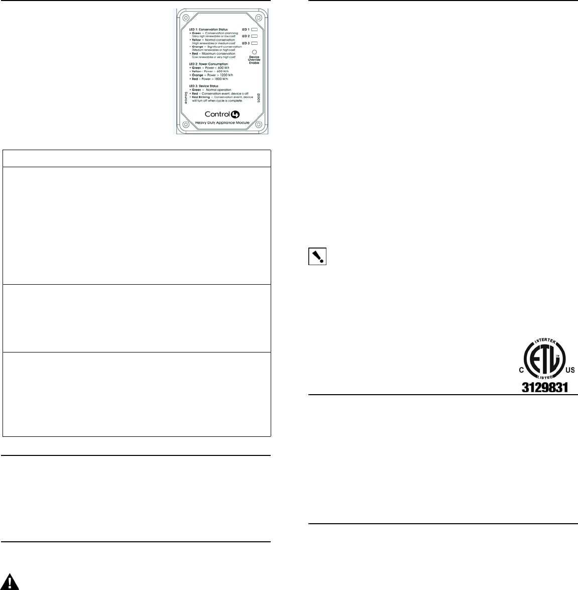
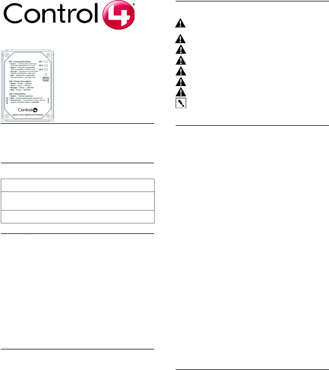
Reading the LEDs
When an LED is enabled in Composer, the
default color scheme is as defined on the
device itself (shown in this figure). The same
information is also outlined in the following
table.
Table 5. LED Color Descriptions
Control4 Technical Support
For help on the installation or operation of this product, email or call the
Control4 Technical Support Center. Please provide your exact model
number. Contact support@control4.com or see the web site
www.control4.com.
Care and Cleaning
WARNING! Unplug device before cleaning. Do NOT use any
chemical cleaners to clean the switch. Clean surface with a soft damp
cloth as needed.
Regulatory Compliance
This product complies with standards established by the following regulatory and test bodies:
•Federal Communications Commission (FCC)
•Industry Canada
•Underwriters Laboratories Inc. (UL)
•Canadian Standards Association (CSA)
FCC
FCC ID: R33C4AM20
This device complies with Part 15 of the FCC Rules. Operation is subject to the following two
conditions: (1) this device may not cause harmful interference, and (2) this device must accept
any interference received, including interference that may cause undesired operation.
This equipment has been tested and found to comply with the limits for a Class B digital device,
pursuant to Part 15 of the FCC Rules. These limits are designed to provide reasonable
protection against harmful interference in a residential installation. This equipment generates,
uses, and can radiate radio frequency energy and, if not installed and used in accordance with
the instructions, may cause harmful interference to radio communications. However, there is
no guarantee that interference will not occur in a particular installation. If this equipment does
cause harmful interference to radio or television reception, which can be determined by turning
the equipment off and on, the user is encouraged to try to correct the interference by one or
more of the following measures:
•Reorient or relocate the receiving antenna.
•Increase the separation between the equipment and receiver.
•Connect the equipment into a wall outlet on a circuit different from that to which the
receiver is connected.
•Consult the dealer or an experienced radio/TV technician for help.
IMPORTANT! Changes or modifications not expressly approved by Control4
could void the user’s authority to operate the equipment.
Industry Canada
This Class B digital apparatus complies with Canada ICES-003.
Cet appareil numérique de la classe B est conforme à la norme NMB-003 du Canada.
IC: 7848A-C4AM15120
Edison Test Labs.
This product has been tested by ETL and found to comply with:
•UL 916, 3rd Edition, “Energy Management Equipment”
•CSA C22.2 No. 14-95, “Standard for Clock-Operated Switches”
Limited 2 Year Warranty
Control4 Corporation (“Control4”) warrants that at the time of first-consumer sale, this product
will be free from defects in material and manufacture. Control4 further warrants that for a
period of 2 years (24 months) after initial consumer sale, the product will function in
accordance with its specification, provided that it is installed and maintained under normal and
proper use. This warranty extends only to products purchased directly from Control4 or an
Authorized Control4 Reseller. If the product proves to be defective in material or workmanship
during the warranty period, it may be returned to the place of purchase and Control4 will, at its
sole option, repair or replace the product with a like product. This warranty provides the
consumer purchaser with specific legal rights, which may vary per state or country. For
complete warranty information, including details on consumer legal rights as well as warranty
exclusions, visit www.control4.com/warranty.
About this Document
United States Patents Pending. Copyright © 2008 Control4 Corporation. Control4 and the
Control4 logo are registered trademarks of Control4 Corporation. All trademarks are properties
of their respective owners. Part Number: 200-00084 Rev B (Draft 1)
LED Label LED Status Description
LED 1:
Conservation
Status
Green = Conservation Planning
(VeryHigh Renewables/Low Cost)
Yellow = Normal Conservation
(High Renewables/Medium Cost)
Orange = Significant Conservation
(Medium Renewables/High Cost)
Red = Maximum Conservation
(Low Renewables/Very High Cost)
Blinking Red = Emergency Demand Reduction Event
LED 2:
Power
Consumption
Green = Idle Mode, Current consumption is <600 W/h
Yellow = Current consumption is < 600 W/h
Orange = Current consumption is >1200 W/h
Red = Current consumption is >1800 W/h
LED 3:
Device
Status
Green = Normal Operation
Red = Conservation Event; Device is Off
Red Blinking = Conservation Event; Device will turn off
when cycle is complete.
Black or
No Color= Not communicating with the Control4 home
automation system.