Snap One C4CA1 Control and Automation Controller CA-1 User Manual UG
Control4 Control and Automation Controller CA-1 UG
Snap One >
Contents
- 1. UG User Manual
- 2. UG Regulatory User Manual
- 3. UG-Regulatory User Manual
UG User Manual
Supported model
• C4-C A1 Control and Automation Controller, CA-1
Introduction
The Control4® CA-1 Control and Automation Controller enables control of lights,
security systems, sensors, door locks, and other devices controlled by IP, ZigBee,
Z-Wave®, or serial connections. The controller has a fast processor, external
antennas for WiFi and ZigBee radios, an internal slot for a Z-Wave module (sold
spearately), and can be powered by PoE. This controller is perfect for home,
apartments, and other installations that do not require IR control or audio
streaming.
After you install and configure the controller with other Control4 devices, your
customers can control their system using the Control4 apps, system remote
controls, touch screens, or other Control4-supported interface devices (sold
separately).
Box contents
• CA-1 Control and Automation Controller
• External power supply with international plug adaptors
• Antennas (2)
Accessories available for purchase
• Control4 Multi-Purpose In-Wall Box (C4-MPIWB-BL)
• Z-Wave Module - Region H (C4-ZWH)
• Z-Wave Module - Region U (C4-ZWU)
• Z-Wave Module - Region E (C4-ZWE)
Warnings
Caution! To reduce the risk of electrical shock, do not expose this
apparatus to rain or moisture.
AVERTISSEMENT ! Pour réduire le risque de choc électrique, n’exposez
pas cet appareil à la pluie ou à l’humidité.
Caution! In an over-current condition on USB, the software disables
the output. If the attached USB device does not appear to power on,
remove the USB device from the controller.
AVERTISSEMENT ! Dans une condition de surintensité sur USB le
logiciel désactive la sortie. Si le périphérique USB connecté ne semble
pas s’allumer, retirez le périphérique du contrôleur.
For more information, visit the Products pages at dealer.control4.com.
Requirements and specifications
Note: We recommend using Ethernet instead of WiFi for the best
network connectivity.
Note: The Ethernet or WiFi network should be installed before starting
the CA-1 controller installation.
Note: The software required to configure this device is Composer Pro.
See the Composer Pro User Guide (ctrl4.co/cpro-ug) for details.
Specifications
Model number C4-CA1
Connections
Network Ethernet—10/100BaseT compatible (required for controller
setup)
Wireless Wireless N (2.4GHz, 802.11n/g/b)
Wireless security WEP, WPA, and WPA2
Wireless antenna External reverse SMA connector
ZigBee Pro 802.15.4
ZigBee antenna External reverse SMA connector
USB port 2 USB 2.0 ports-500mA
Serial out 1 serial out RJ45 port (RS-232, RS-422, or RS-485)
Z-Wave Integrated Z-Wave slot accepts Control4 Z-Wave modules
(sold separately)
Power
Power requirements 5VDC 3A, external power supply included
Power supply AC power supply accepts 100-240V ~ 50-60 Hz (0.5A)
PoE 802.3af (<13 W)
Power consumption TBD
Miscellaneous
Operating temperature 32˚ - 104˚ F (0˚ - 40˚ C)
Storage temperature 4˚ - 158˚ F (-20˚ - 70˚ C)
Dimensions (H x W x D) 5.5" x 5.5" x 1.25"
Weight 1.2 lb (.54 kg)
Shipping weight 2.2 lb (1.0 kg)
Additional resources
The following resources are available for more support.
• Control4 Knowledgebase: kb.control4.com
• Dealer Forums: forums.control4.com
• Control4 Technical Support: dealer.control4.com/dealer/support
• Control4 website: www.control4.com
• Composer Pro documentation in online help or PDF format available on the
Dealer Portal under Support: ctrl4.co/docs
• Z-Wave documentation: ctrl4.co/z-wave
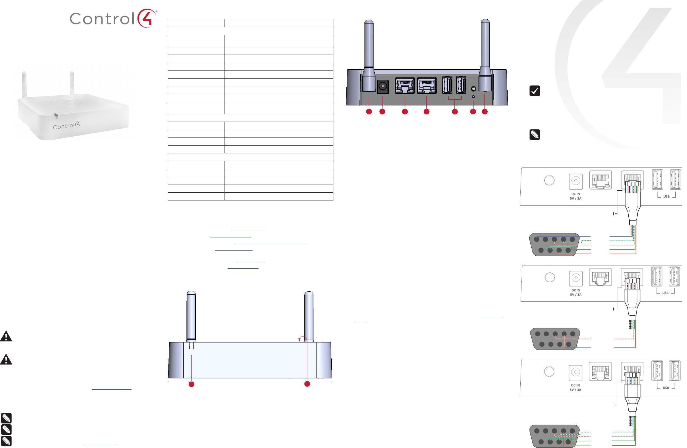
Front view
A Status LED—The RGB status LED gives system status feedback. See
“Troubleshooting” in this document for LED status information.
B Z-Wave port—Removable plastic cover on top of the controller with a Z-Wave
port underneath for a Control4 Z-Wave module.
AB
Connecting the serial port (optional)
The controller includes one RJ-45 serial port that can be configured for RS-232,
RS-422, or RS-485 serial communication.
The following serial communication configurations are supported:
• RS-232—Hardware flow control, up to 115,200 Kbps.
(TXD, RXD, CTS, RTS, GND)
• RS-485—Single twisted pair, half duplex
• RS-422—Two twisted pair, full duplex
To set up the serial port:
1 Connect a serial device to the controller using Cat5/Cat6 cable and an RJ-45
connector.
Important: The serial port pinout follows the EIA/TIA-561 serial wiring
standard. Standard Cat5/Cat6 Ethernet cabling (EIA/TIA-568) would
result in split D+ and D- data pairs, causing reduced performance in
RS-485/RS-422 applications. Use the wiring shown in the diagrams
below.
2 To configure the serial port settings, make the appropriate connections in
your project using Composer Pro. See the Composer Pro User Guide for
details.
Note: Serial settings are defined in the device driver in Composer. Serial
settings (baud, parity, and serial port type) are automatically configured
when a device driver is connected in Composer Pro to the serial port
connection of the CA-1 driver.
Serial port pinout and wiring recommendations
9 8 7 6
1234
5
ETHERNET
ZIGBEE WIFI
Pin 4 SG
Pin 5 RXD
Pin 6 TXD
Pin 7 CTS
Pin 8 RTS
Pins 1-3 not used
EIA-561 wiring recommended
DB9 rear view
RS-232 pinout
Back view
A ZIGBEE—External antenna connector for ZigBee radio.
B Power port—Power connection for external power supply.
C ETHERNET (PoE)—RJ-45 port for 10/100BaseT Ethernet network connection.
Network connection used for configuration and device control. Supports PoE.
D SERIAL—RJ-45 port for serial communications. Can be used for RS-232, RS-
422, or RS-485 communication for device control.
E USB—Two USB 2.0 ports for external USB drives (e.g., FAT32-formatted
devices). See “Setting up external storage devices” in this document.
F ID / RESET buttons—Buttons used to identify the device in Composer Pro and
reset the controller. See “Troubleshooting” in this document.
G WIFI—External antenna connector for 2.4 GHz 802.11n/g/b WiFi radio. WiFi
connection can be used for device control, but controller must have a wired
connection for initial setup.
Installing the controller
Requirements:
• Ensure that the home network is in place before starting system setup.
• A wired connection to the network is required for initial controller setup.
• The controller requires a network connection (Ethernet is recommended or
WiFi) to use all of the features as designed. When connected, the controller
can communicate with other IP devices in the home and access Control4
system updates.
• Composer Pro software version 2.10.0 or newer is required for configuration.
Mounting options:
• On-wall—The controller can be mounted to the wall using screws. Remove
the rubber feet, measure the distance between them, and insert 2 screws into
the wall so that the heads are about 1/4 to 1/2 inch from the wall. Position
the holes on the back of the controller over the screw heads and slide the
controller onto the screws.
• In-wall—The controller can be mounted in the wall, behind a TV or other
equipment for a discreet installation. The Control4 Multi-Purpose In-Wall Box
is sold separately and is designed for use with the CA-1 and other Control4
equipment. See the Multi-Purpose In-Wall Box Installation Guide (ctrl4.co/
iwb-ig) for more details.
• DIN rail—The controller can be mounted to the wall using a section of DIN rail
channel. Mount the rail to the wall, and then attach the controller to the rail.
Connecting the controller
1 Connect the controller to the network.
• Ethernet—To connect using an Ethernet connection, plug the data cable
from the home network connection into the controller’s RJ-45 port
(labeled “Ethernet”) and the network port on the wall or at the network
switch.
• WiFi—To connect using WiFi, first connect the unit to Ethernet, attach
the WiFi antenna to the controller, and then use Composer Pro System
Manager to reconfigure the unit for WiFi.
2 Attach serial devices as described in “Connecting the serial port.” Serial
port is only used for controlling external devices, the controller must be
connected over Ethernet or WiFi to set up the Control4 programming.
3 Connect any external storage devices (USB) as described in “Setting up
external storage devices” in this document.
4 Connect the power cord to the controller’s power port and then into an
electrical outlet (if the controller is not powered by PoE).
BA C D EFG
CA-1 Control and
Automation Controller
Installation Guide
ETHERNET
ZIGBEE WIFI
9 8 7 6
1234
5
Pin 6 DATA+
Pin 8 DATA-
Pins 1-5, 7
not used
EIA-561 wiring recommended
DB9 rear view
RS-485 pinout
9 8 7 6
1234
5
ETHERNET
ZIGBEE WIFI
Pin 5 RXD+
Pin 6 TXD+
Pin 7 RXD-
Pin 8 TXD-
Pins 1-4 not used
EIA-561 wiring recommended
DB9 rear view
RS-422 pinout
control4.com | 888.400.4070
Copyright ©2017, Control4 Corporation. All rights reserved. Control4, the Control4 logo,
the 4-ball logo, 4Sight, Control4 My Home, and Mockupancy are registered trademarks
or trademarks of Control4 Corporation in the United States and/or other countries. All
other names and brands may be claimed as the property of their respective owners. All
specifications subject to change without notice.
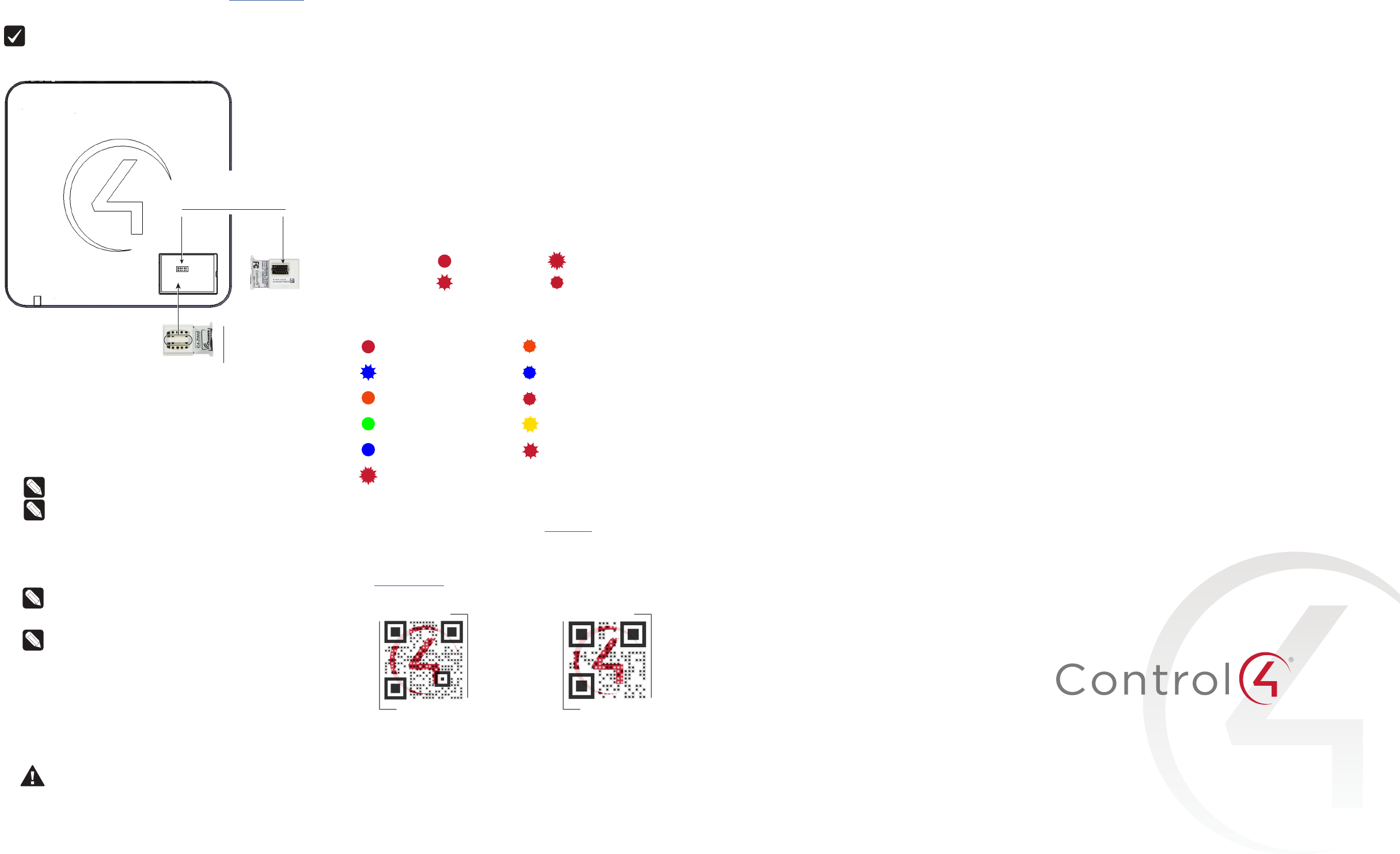
Installing a Z-Wave module (optional)
An optional Z-Wave module can be added to the Z-Wave port on top of the
controller. Z-Wave Modules are specific to your region. See the Z-Wave Setup
Guide for software configuration and more information (ctrl4.co/z-wave-sg)
To install the a Z-Wave module into the controller:
Important: Power o the controller before you install the Z-Wave Module.
1 Using a small flathead screwdriver, remove the small plastic cover on top of
the Z-Wave module.
4 Replace the plastic cover.
Setting up external storage devices
You can store and access media from an external storage device, for example, a
network hard drive or USB memory device, by connecting the USB drive to the
USB port and configuring or scanning the media in Composer Pro.
Note: We support only externally-powered USB drives or solid state
USB sticks. USB-powered external hard drives are not supported.
Note: When using USB storage devices with the CA-1 controller you can
only use one partition with a 2TB maximum size. This limitation applies
to USB storage devices with all other controllers also.
Composer Pro driver information
Use Auto Discovery and SDDP to add the driver to the Composer project. See the
Composer Pro User Guide for details.
Note: A CA-1 controller may only run as Director in a single-controller
project. CA-1 controllers may be used as secondary controllers in
projects with other controllers that can be a Director in a multiple-
controller project.
Note: The CA-1 controller requires OS 2.10.0 or higher.
Connecting Z-Wave and ZigBee devices
All software configuration including connecting ZigBee and Z-Wave devices is
done with Composer Pro. See the Composer Pro User Guide for more information.
Troubleshooting
Reset to factory settings
Caution! The factory reset process will remove the Composer project.
To restore the controller to the factory default image, perform the following
steps:
1 Insert one end of a paper clip into the small hole on the back of the
controller labeled RESET.
Note the location of the con-
nector on the Z-Wave port and
the location of the connector
on the Z-Wave module
Orient the Z-Wave module to
fit in the port opening, hold it
by the tab on top of the
module, and insert it straight
down into the port.
2
3Orient the Z-Wave
module to fit in the port
opening, hold it by the
tab on top of the module,
and insert it straight
down into the port.
Note the location of the connector on
the Z-Wave port and the location of
the connector on the Z-Wave module.
2 Press and hold the RESET button, the controller will reset and the Status LED
will go solid red.
3 Hold the button until the LED blinks double yellow. This should take five to
seven seconds. The LED will blink yellow while the factory restore is running.
When complete, the LED will turn o and the device will reset to complete
the factory restore process.
Power cycle the controller
Press and hold the ID button for five seconds. The controller will restart.
Reset the network settings
To reset the controller network settings to the default, follow these steps:
1 Disconnect power to the controller.
2 While pressing and holding the ID button on the back of the controller,
power on the controller.
3 Hold the ID button until the LED is solid blue, then immediately release the
button.
4 If during the boot sequence the LED stays orange, press and hold the ID
button until the LED blinks blue, and then release it.
LED troubleshooting guide
LED legend: = solid = flashing (4 Hz)
= flashing (1 Hz) = flashing (1/2 Hz)
Status LED
Power up No IP address
Controller is booting Controller is updating
Reset check Update error
Boot complete Factory restore in progress
Connected to Director (link) Factory restore error
USB over-current detected
Regulatory/Safety information
To review regulatory information for your particular Control4 products, see the
information located on the Control4 website at ctrl4.co/reg.
Warranty
Visit ctrl4.co/warranty for details.
More help
For the latest version of this document and to view additional materials, open the
URL below or scan the QR code on a device that can view PDFs.
DOC-00297-A
2017-10-18 DH
A
MOST RECENT VERSION
ctrl4.co/ca1-ig
MORE INFO ON CA CONTROLLERS
ctrl4.co/ca