User Manual
™Requirements
• Toolstoinstallthebackbox,suchasatape
measure,pencil,hammerorscrewdriver
• Nailsorscrews(4to6)
• AntennaKits(optional,soldseparately)
-Antenna,12”(C4-AK-26cm)
-ExternalAntenna,10’,EWA2450M(C4-AK-3M)
Specifications
Dimensions
(HxWxD)
6.1”x4.1”x3”(156mmx104mmx76mm)
Weight 1.10lbs.
Network EthernetorWiFi(802.11b/g/n)
Grounding Requirements
Thefollowingtableindicateswhichpoweroptions
requireanearthground.
Power Type Earth Ground?
AC Yes,requiredforsafety.
PowerOverEthernet(PoE) No.Donotconnect.
DC Recommended;notrequired.
Network and Power Considerations
ThisdeviceusesanEthernetorWiFinetwork
connectionandcanbepoweredusingPoE,AC,or
DC.
NOTE:ItisrecommendedtouseEthernet
ratherthanWiFiforthebestnetwork
connectivity.SeetheDoor Station - Exterior
Setup Guideforwiringinstallationdetails.
Mounting Tips
Followthesetipsforbestresults.
1 InstalltheDoorStationinaplacewhereitwillbe
protectedfromwater(e.g.,rain,sprinklers,etc.).
2 DonotexposetheDoorStationtodirect
sunlight.Forinstallationsindirectsunlight,the
SatinNickelmodel(C4-DCS-EN-SN)willyieldthe
leastamountofcolorfading.
3 Findanappropriateexteriorlocationforthe
DoorStation.AlsoseetheDoor Station - Exterior
Setup Guideforbackboxplacement.
a MounttheDoorStationwherethevideo
Supported Model
• C4-DSBB-E-MDoorStationMetalBackBox
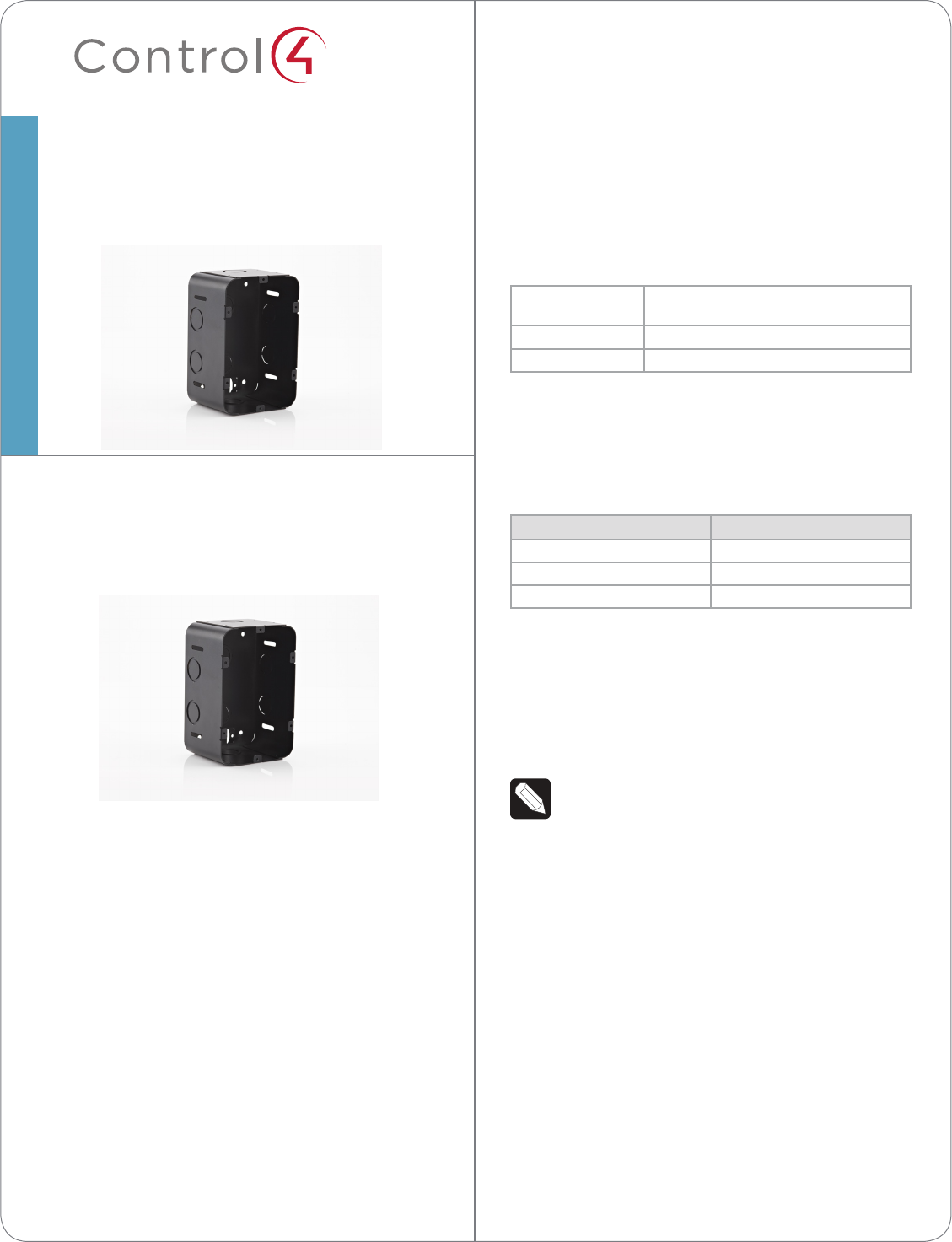
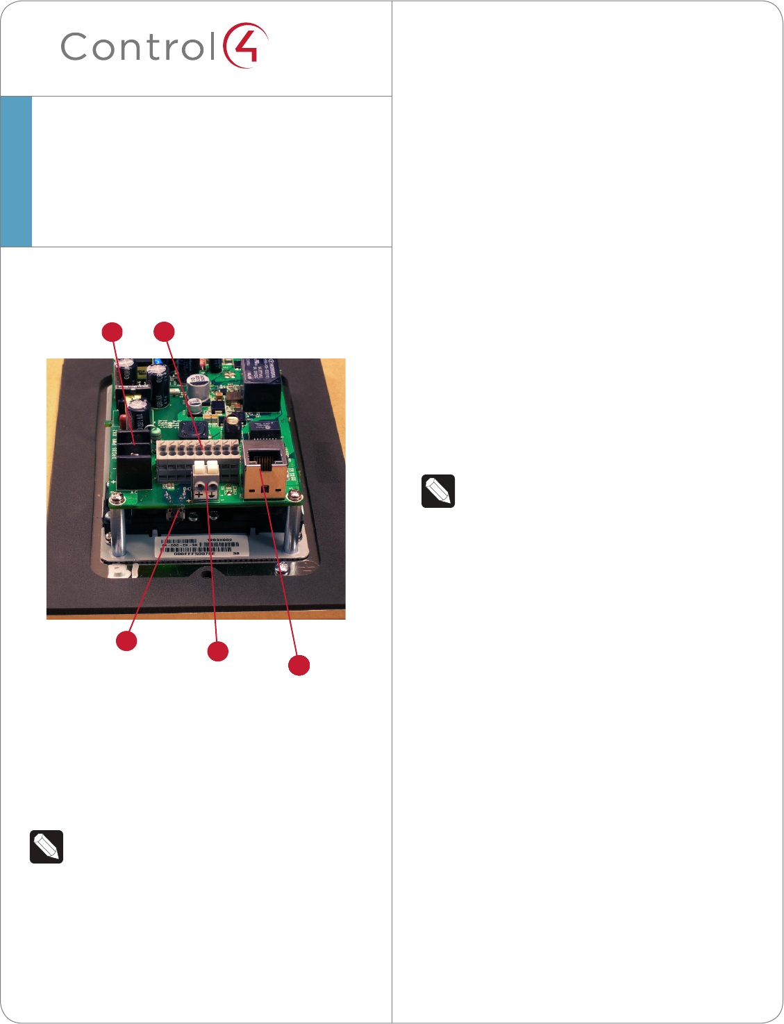
Figure1.DoorStationBackBox
General Description
Control4®providesabackboxtoaccommodatethe
installationofaControl4DoorStation-Exterior(C4-
DSC-EN-xx).
Box Contents
UnpacktheDoorStationBackBoxandensurethe
followingitemsareincludedinthebox.
ContactyourControl4Dealerimmediatelyifyound
anymissingordamagedcomponents.
• Control4DoorStationBackBox
(modelC4-DSBB-E-M)
DoorStationBackBox
InstallationGuide
1
™
cameraisaimedatanaverageperson’s
heightsotheviewercanseetheperson
callingin.
b MounttheDoorStationsothatthecallercan
comfortablyspeakintothemicrophoneor
about18”to2’away(45cmx60cm).
4 Itisnotrecommendedtousewireless(WiFi)
foranoutsideinstallation.IfyouuseWiFi,follow
thesetips:
• PlacetheDoorStationinalocationwherethe
wirelesssignal(WAPbroadcast)isstrong.
• Placetheaccesspointinaclearlineofsightor
lessthan100feet,ifpossible.
• Placetheaccesspointwhereitwillhavetheleast
numberofwallstopassthrough.
• Placetheaccesspointonthesecondlevelbya
window.
• UseComposerPro’s,SystemManagertotestthe
wirelesssignalafteryou’veinstalledtheDoor
Station.
• Verifythatthesignalworks.
SeetheDoor Station - Exterior Setup Guide(when
theDoorStationisreleased)forWiFiinstallation
instructions.
Installation
NOTES:(1)Placethebackboxbetweenstuds.
Donotattempttoinstallabackboxovera
wallstud.(2)ToconformtoNEMAsafety
standards,installastrain-reliefcord(sold
separately)inthepunchoutonthebackbox
beforeinsertingthewires.See“Regulatory
Information”ortheNEMAwebsiteat:http://
www.nema.org/stds/fordetails.
DoorStationBackBox
InstallationGuide
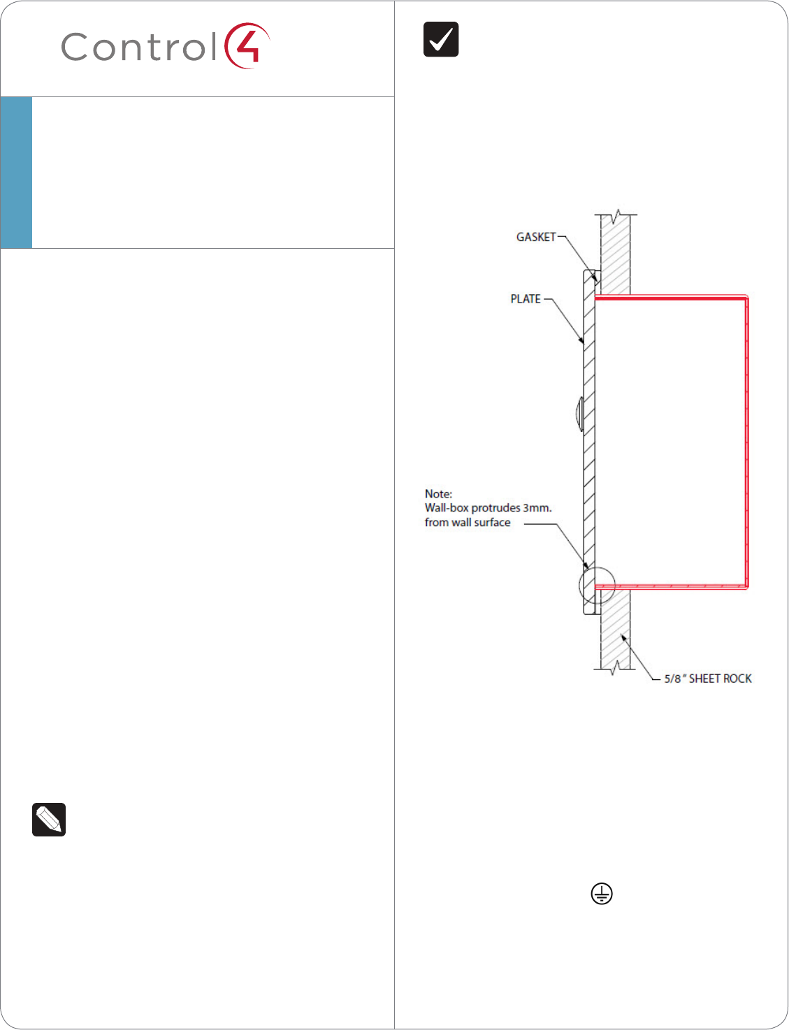
IMPORTANT!Makesurethebackbox
protrudesfarenoughout(0.118”or3mm)
fromtheexteriorwallsurface(brick,rock,
stucco,wood,concrete,etc.)toallowthe
plateandgaskettosealtheDoorStation(see
Figure2).
Figure2.BackBoxSideViewinWallwithDoor
StationFaceplate
1 FeedtheAC,DC,orPoEwiresthroughatab
inthebackofthebackbox.SeetheDoor
Station - Exterior Setup Guidetodetermineyour
installationoption.
2 Afterplacingthebackboxinsidethewall,secure
theboxwithscrewsornails.
3 Attachthegroundwirestothebackboxas
needed(see“GroundingRequirements”onpage
1)andDoorStationplateinthelocationindicated
bythegroundsymbol(seeFigures3and4).
Therearetwo(2)groundscrewsintheback
box:one(1)forEarthgroundandone(1)for
groundingtheDoorStationfaceplatetotheback
box.
2
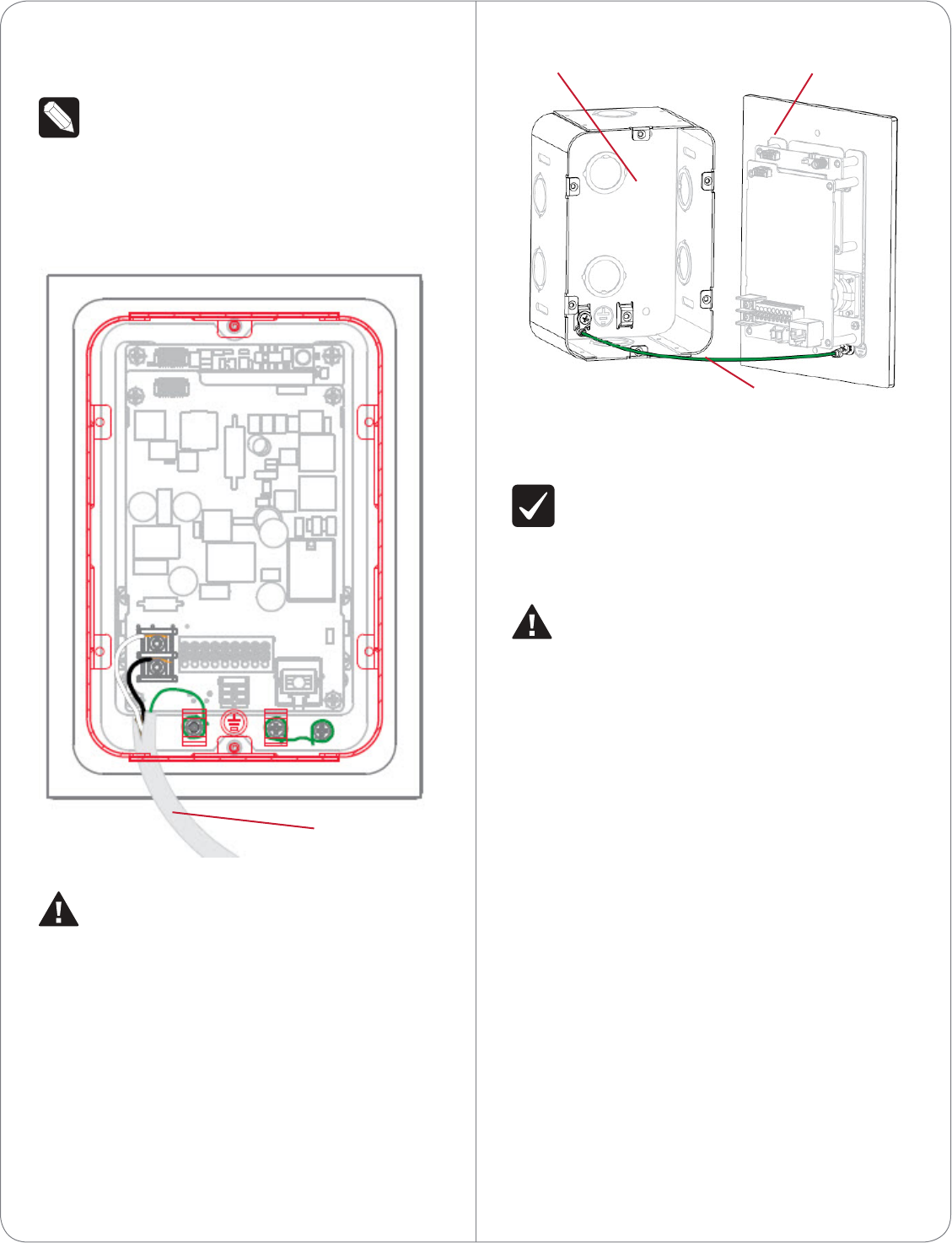
Figure4.GoundWiresfromDoorStationtoBackBox
Warnings
IMPORTANT!Improperuseorinstallationcan
causeLOSS/DAMAGEOFPROPERTY.
Important!L’utilisationoul’installationinexacte
peutcauserLOSS/DAMAGEDEPROPRIÉTÉ.
WARNING!BeforeyouinstalltheDoorStation
BackBoxusingAC,switchothecircuit
breakerorremovethefusefromthefusebox.
AVERTISSEMENT!Pourl’endroitoùvous
installezstationdeporteavecAC,coupezle
disjoncteurouenlevezlefusibledelaboîtede
fusible.
Regulatory/Safety Information
Toreviewregulatoryinformationforyourparticular
Control4products,seetheinformationlocatedon
theControl4websiteat:http://www.control4.com/
regulatory/
4 IfusingWiFi,theWiFiantennamustbeinstalled
inthebackboxandextendoutsidethebox.
NOTE:Donotallowanycontactofthe
antennaelementtoanymetalsurfaceonthe
backbox;otherwise,antennaperformancewill
diminish.
Figure3.GroundWiretoDoorStation
WARNING!ForACinstallation,failureto
groundthemetalbackboxandDoorStation
faceplateproperlycanresultinapotentially
hazardouscondition.
AVERTISSEMENT!Pourinstallationd’AC,
défautdebrancherlamiseàlaterredela
boîtearrièreenmétaletlafaçadeavant
correctementpeutentraînerunesituation
dangereuse.
3
Ground Wire
Ground Wire
Back Box Door Station Faceplate

©2012 Control4. All rights reserved. Control4, the Control4 logo, the Control4 iQ logo and the Control4 certified logo are registered trademarks or trademarks
of Control4 Corporation in the United States and/or other countries. All other names and brands may be claimed as the property of their respective owners.
control4.com| ™
4
Warranty
Limited2-yearWarranty.Gotohttp://www.control4.
com/warrantyfordetails.
About This Document
Partnumber:200-00244,Rev.E6/05/2012
™Specifications
Dimensions (H x
W x D)
7.19” (182 mm) x 5.13” (130 mm) x 2.3” (58
mm)
Weight 3.25 lbs. (1.474 kg)
Shipping Weight 3.25 lbs. (1.474 kg)
Network 10/100 BaseT Ethernet (preferred) or WiFi
(802.11 b/g/n)
Voltages AC - 100V - 240V
DC - 12V - 24V
Contacts (2 sets) DC: 48V
maximum operation (low voltage)
Relays (1) AC: 36V, 2A
DC: 24V
maximum operation (low voltage)
Grounding Requirements
The following table indicates which power options
require an earth ground.
Power Type Earth Ground?
AC Yes, required for safety.
Power over Ethernet (PoE) No. Do not connect.
DC Recommended; not required.
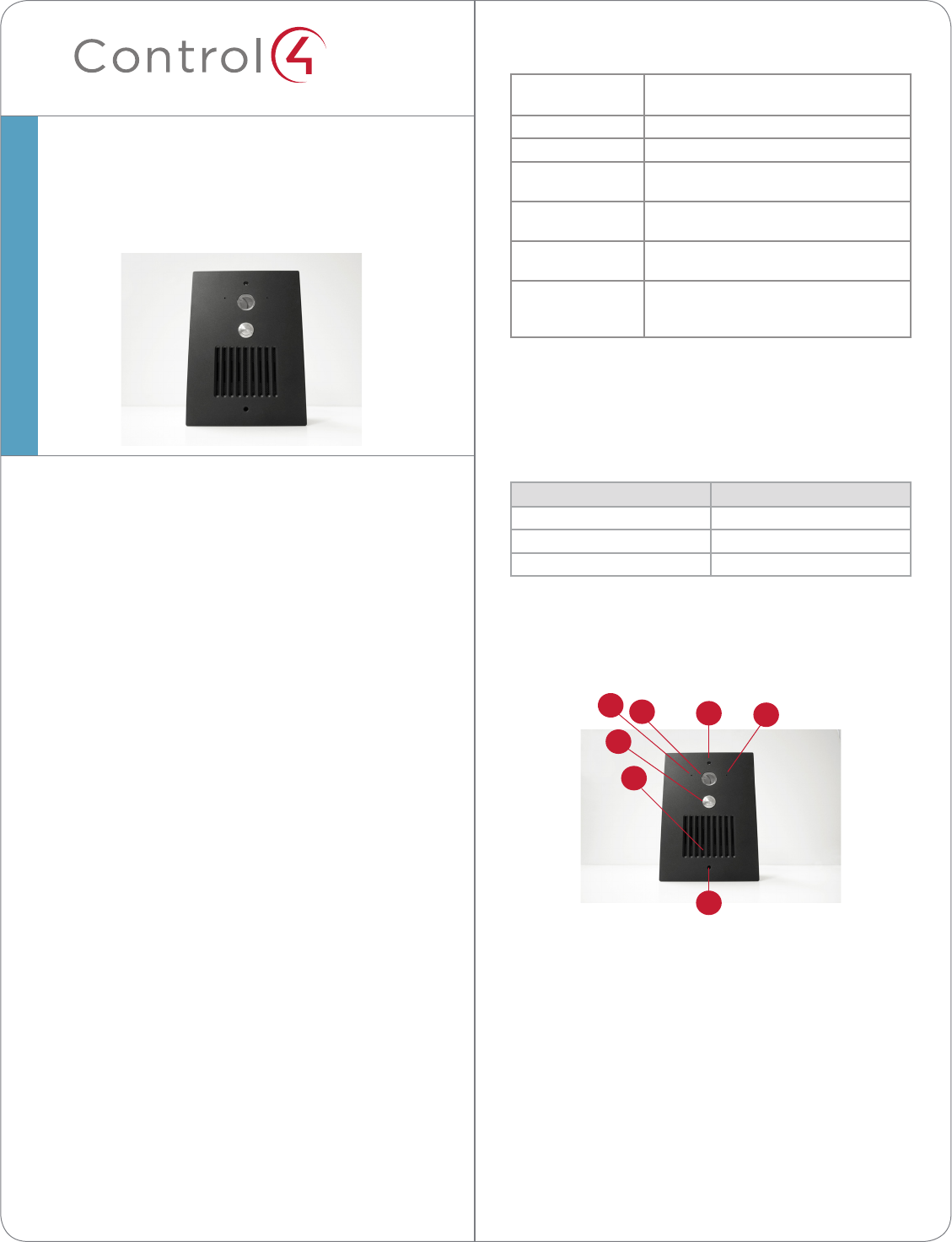
Front Panel Description
Figure 1. Front Faceplate
1 Camera. 640 x 480 wide angle. Used for Video
Intercom.
2 Call button. Used to call the person inside the
structure.
3 Speaker. Used for Audio and Video Intercom.
4 Screw holes (2). Used to screw the faceplate into
the exterior wall.
5 Microphones (2). Used for Audio and Video
Intercom.
Supported Models
• C4-DSC-EN-BL Door Station - Exterior
AC, DC, POE & WiFi - Satin Black
• C4-DSC-EN-SN Door Station - Exterior
AC, DC, POE & WiFi - Satin Nickel
• C4-DSC-EN-VB Door Station - Exterior
AC, DC, POE & WiFi - Venetian Bronze
Box Contents
Carefully unpack the Control4® Door Station from the
box and ensure that the following items are included
in the box. Contact your Control4 Dealer immediately
if any parts are missing or if any components are
damaged.
• Control4 Door Station - Exterior faceplate (model
C4-DSC-EN-xx)
• Two (2) mounting screws
• Security screw tool
• Warranty Card
Accessories
• Door Station Metal Back Box (C4-DSBB-M, sold
separately)
• Antenna Kit—WiFi/ZigBee 2.4 GHz, 26cm
(C4-AK-26cm, sold separately)
• Antenna Kit—WiFi/ZigBee 2.4 GHz, 3m
(C4-AK-3M, sold separately)
Door Station - Exterior
Setup Guide
1
2
3
4
45
5
1
™
Inside Panel Description
Figure 2. Door Station, Inside Panel
1 AC connection. Used to connect the wires for AC
power.
2 DC connection. Used to connect the wires for DC
power.
3 Contacts/Relays. Used to connect the wires for
Control4 and third-party devices.
NOTE: Use the contacts and relays for non-
secure devices only. For example, don’t attach
security gate wires to this terminal block.
4 Ethernet connection. Supports PoE.
5 Reset Button. Used to reset or factory restore the
Door Station.
Door Station - Exterior
Setup Guide
Pre-Installation
1 Find the best exterior location for the Door
Station. See “Mounting Tips” below.
2 Install the Door Station Back Box. See the Door
Station Back Box Installation Guide for details.
3 Determine which network and power options
to use (see “Network Options” and “Power
Options”).
4 (WiFi only). Before the Door Station is fully
installed, Control4 recommends to test the
WiFi signal strength in Composer Pro’s System
Manager; a strong, robust signal is required. See
the Composer Pro User Guide for details.
This device uses an Ethernet or WiFi network
connection and can be powered using Power
over Ethernet (PoE), AC, or DC. A wired network
connection is recommended for the best Video
Intercom experience. If it is not possible to use
Ethernet, then please follow these guidelines for
wireless.
NOTES: (1) Video Intercom usage. Although
this device supports b/g/n, 802.11 b is not
recommended or supported for Video
Intercom. (2) Wireless-N is recommended
for Video Intercom. See “Wireless Network
Limitations” below.
Wireless Network Limitations
Many WiFi Access Points handle Multicasts
(WiFi simultaneously sent to multiple devices,
for example, when the Door Station broadcasts
video to all stations) by slowing down
transmission speed to the 1 Mb basic rate. This
can cause overall WiFi congestion in the WiFi
network during the broadcast. Video Intercom
response times and images may degrade at
each device.
If a home requires a large number of WiFi
Video Intercom devices, ensure that you have
a robust WiFi network (possibly consisting of
multiple access points).
Mounting Tips
Follow these tips for the best results.
2
3
52444444444444
1
installation option that works best with the system
before installing the Door Station.
Power Options
CAUTION! Do not attempt to use PoE, AC, and
DC power at the same time. Choose only one
power option.
ATTENTION! Ne pas tenter d’utiliser PoE,
AC et DC en même temps. Choisir une seule
option d’alimentation.
The Door Station can be powered using one of these
three (3) options:
• Power over Ethernet (PoE). The Ethernet
network connection for the Door Station is
provided through the PoE Injector. No additional
wiring is needed.
• AC or DC. Used to power the Door Station when
using an Ethernet (not PoE) or WiFi network
connection.
NOTE: Ethernet cable. Install the ferrite clamp
on the Ethernet cable inside the back box.
Backlit Button Indicator
The Door Station button’s light can be turned on or
o depending on what is required for the installation.
The backlit button may make it easier to see the
button when it is dark outside. Normally, the light on
the button remains on or o depending on how it is
configured in the system, however, it is also used to
convey device status during certain times.
When the device is first powered on, the button will
blink slowly until the device is ready to be used in
the system. If the button continues to blink slowly for
over 3 minutes, then the device may be experiencing
a problem and should be factory restored. During a
factory restore process the button will blink rapidly.
1 Install the Door Station in a place where it will be
protected from water (e.g., rain, sprinklers, etc.).
2 Do not expose the Door Station to direct
sunlight. If the sun hits the Door Station, Control4
recommends to purchase the Satin Nickel
model (C4-DCS-EN-SN) to reduce fading and
degradation of the Door Station.
3 Find the best exterior location for the Door
Station. See the Door Station Back Box
Installation Guide for back box installation.
a Mount the Door Station where the video
camera is aimed at an average person’s
height so the person inside the building gets
a good view of the person calling in.
b Mount the Door Station so that the caller
can comfortably speak into the microphone
(about two (2) feet away or 60 cm).
4 Control4 does not recommend using wireless
(WiFi) networking for an exterior installation.
If you must use WiFi, however, follow these
guidelines:
• The wireless access protocol (WAP) broadcast to
the exterior location must be strong.
• Use Composer Pro’s System Manager to test the
wireless signal after you’ve installed the Door
Station, and then verify that the signal works
correctly. See the Composer Pro User Guide for
details.
Network Options
The Door Station can be connected using one of
these network types:
• Standard Ethernet. For best results, this is the
preferred option. Connect the Door Station to
the RJ-45 LAN port on using the RJ-45 Ethernet
cable.
• WiFi. The WiFi antenna will communicate with
the LAN’s WAP. If the LAN has a WAP set up, no
additional wiring is needed except for power. See
“WiFi Antennas” for details.
IMPORTANT! (1) Control4 recommends to use
an Ethernet connection rather than WiFi for
the best communication with the Control4
system. (2) WiFi requires an antenna (sold
separately).
Please read the next sections, “Power Options”
> “Network and Power Installations” to choose an
3
Power and Network Installations
Choose one of these six (6) options to connect the
Door Station’s wiring:
• Ethernet with PoE (preferred)
• Ethernet with AC
• Ethernet with DC
• WiFi with AC
• WiFi with DC
• WiFi with PoE
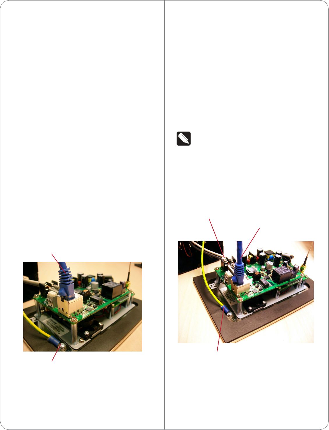
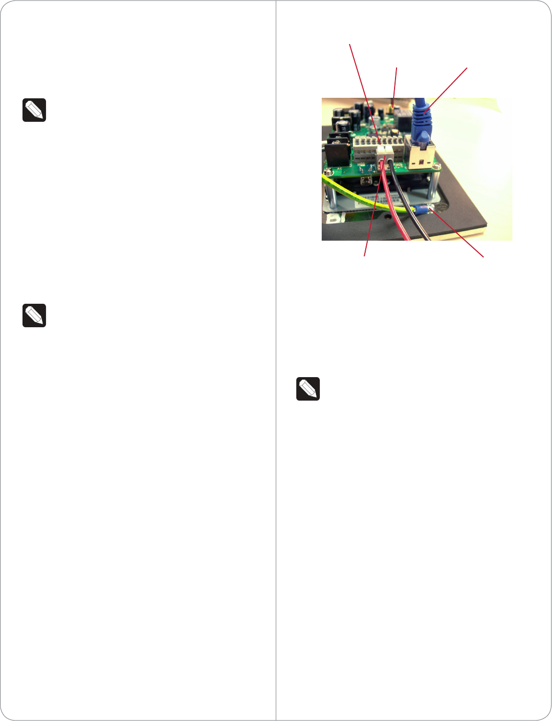
Option 1 (Preferred): Ethernet Connection with a
PoE Injector or a Third-Party Injector or Switch
This option sets up Ethernet with PoE.
PoE injects electrical current into the Ethernet cable
using a PoE Injector - model #AC-POE1-B, or a
third-party PoE solution to provide the Door Station
with power and a network connection.
To install the Door Station with a PoE and Ethernet
connection using a PoE Injector:
1 Plug the Ethernet cable into the Door Station
(see Figure 3).
2 See the section “Grounding Requirements” for
details about earth grounding.
Figure 3. Ethernet with PoE Injector
Option 2: Ethernet Connection with AC Power
This option sets up Ethernet and AC power.
To install the Door Station with Ethernet and AC
power:
1 Plug the Ethernet cable into the Door Station
(see Figure 4).
2 Connect a ground wire from the Door Station to
one of the back box lugs (see Figure 12).
3 Connect a second earth-ground or house-ground
wire from the second back box lug to the home.
See “Grounding Requirements” for details about
earth grounding.
4 Connect the neutral (N) (-) and hot (L) (+) wires
to the AC power source for the Door Station
according to the national and local electrical
codes.
TIP: The hot or ‘L’ (+) wire’s connector is
closest to the bottom of the Door Station’s
plate.
5 Your installation may require alternative wires and
the use of a terminal block. Strip the power wires
to 1/4” on the end if necessary.
Figure 4. Ethernet with AC Power
Option 3: Ethernet Connection with DC Power
This option sets up Ethernet and DC power.
To install the Door Station with Ethernet and DC
power:
4
Ground Wire
Ethernet Cable
AC Connections
(Hot and Load)
Ethernet Connection
Ground Wire
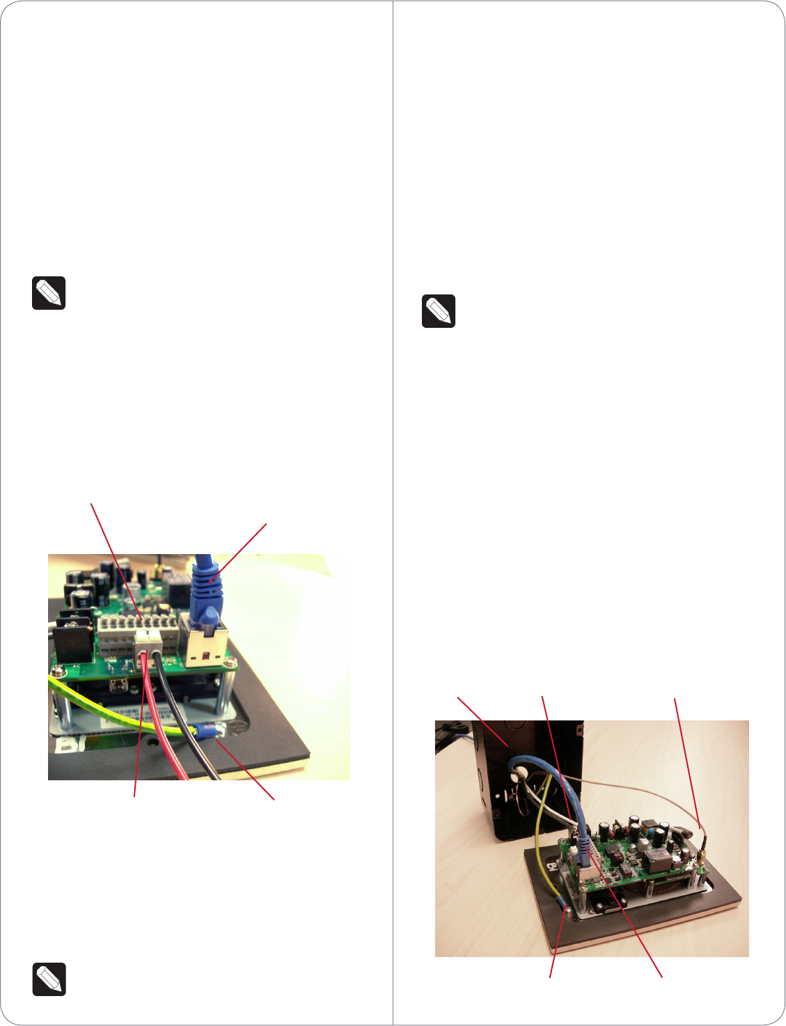
1 Plug the Ethernet cable into the Door Station
(see Figure 5).
2 Connect a ground wire from the Door Station to
one of the back box lugs (see Figure 12).
3 Connect a second earth-ground or house-
ground wire from the second back box lug to the
home. See “Grounding Requirements” for details
about earth grounding.
4 Connect the negative (-) and positive (+) wires
to the DC power source for the Door Station
according to the national and local electrical
codes.
TIP: The positive (+) wire’s connector is
located on the bottom left side of the Door
Station’s plate.
5 Your installation may require alternative wires
and the use of a terminal block (see Figure
5). Strip the power wires to 1/4” on the end if
necessary.
Figure 5. Ethernet with DC Power
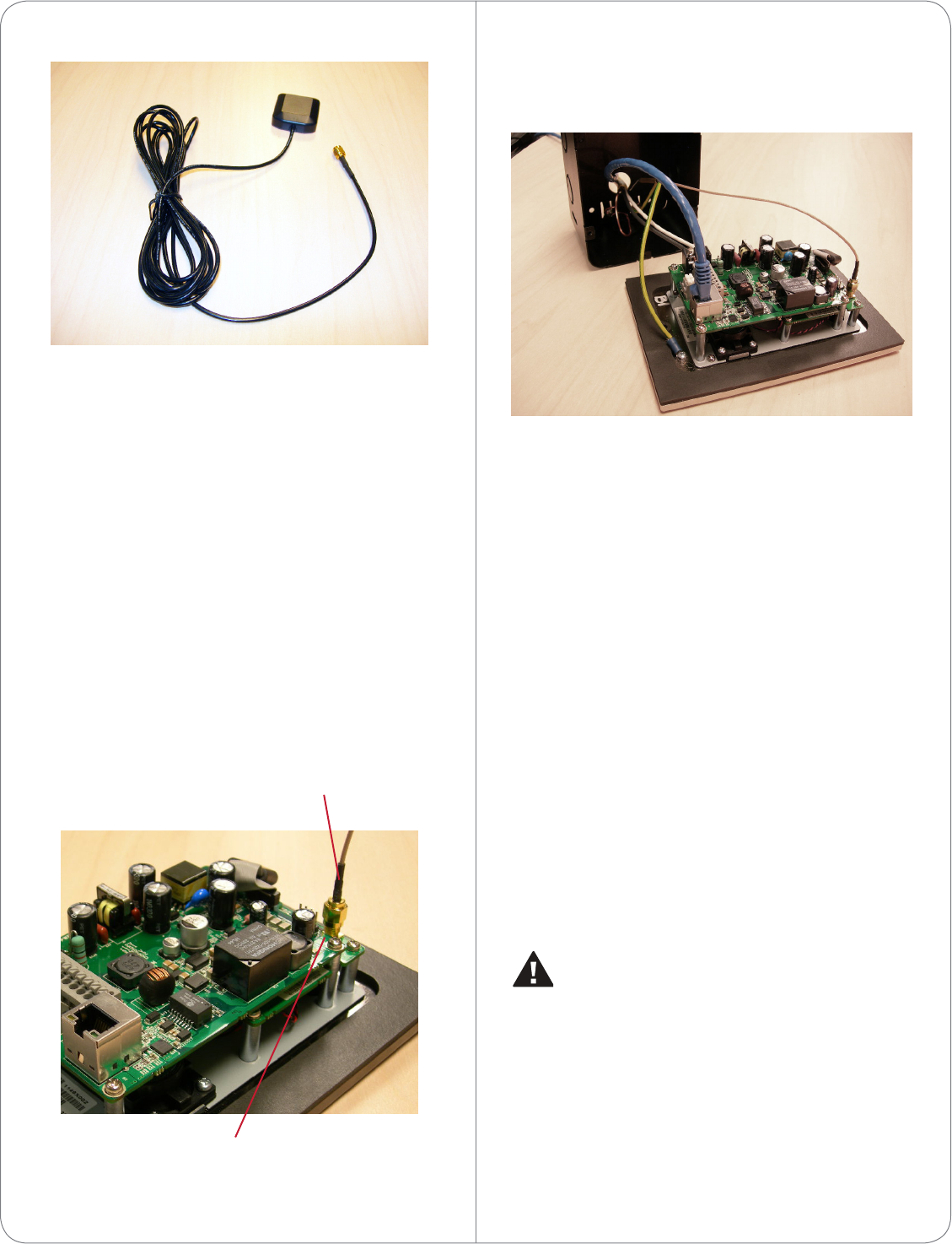
Option 4: WiFi Connection with AC Power
This option sets up WiFi and AC power.
Ensure that you have WiFi in the home.
NOTE: WiFi requires an antenna (sold
separately).
To install the Door Station with WiFi and AC power:
1 Connect a ground wire from the Door Station to
one of the back box lugs (see Figure 6).
2 Connect a second earth-ground or house-ground
wire from the second back box lug to the home.
See “Grounding Requirements” for details about
earth grounding.
3 Connect the neutral (N) (-) and hot (L) (+) wires
to the AC power source for the Door Station
according to the national and local electrical
codes.
TIP: The hot or ‘L’ (+) wire’s connector is
closest to the bottom of the Door Station’s
plate.
4 Your installation may require alternative wires and
the use of a terminal block. Strip the power wires
to 1/4” on the end if necessary.
5 Attach the antenna (3m or 26cm) to the Door
Station. See “WiFi Antenna Kit Installation” for
details.
6 Run the antenna wire through the back box hole
(see Figure 6). Ensure that the wire doesn’t touch
the back box.
7 Align the antenna vertically to the wall outside
the back box (26cm antenna) or run the antenna
through the wall (3m antenna). See “WiFi
Antennnas” for details.
Figure 6. WiFi with AC Power
5
Contacts and Relays
Ethernet Cable
Ground Wire
DC Connections
(Hot and Load)
AC Connections
(Hot and Load)Back Box
Ground Wire Ethernet Connection
Antenna
Option 5: WiFi Connection with DC Power
This option sets up WiFi and DC power.
Ensure that you have WiFi in the home.
NOTE: WiFi requires an antenna (sold
separately).
To install the Door Station with WiFi and DC power:
1 Connect a ground wire from the Door Station to
one of the back box lugs (see Figure 12).
2 Connect a second earth-ground or house-ground
wire from the second back box lug to the home.
See “Grounding Requirements” for details about
earth grounding.
3 Connect the negative (-) and positive (+) wires
to the DC power source for the Door Station
according to the national and local electrical
codes.
NOTE: The positive (+) wire’s connector is
located on the bottom left side of the Door
Station’s plate.
4 Your installation may require alternative wires and
the use of a terminal block. Strip the power wires
to 1/4” on the end if necessary.
5 Attach the antenna (3m or 26cm) to the Door
Station. See “WiFi Antenna Kit Installation” for
details.
6 Run the antenna wire through the back box hole
(see Figure 12). Ensure that the wire doesn’t
touch the back box.
7 Align the antenna vertically to the wall outside
the back box (26cm antenna) or run the antenna
through the wall (3m antenna).
Figure 7. WiFi with DC Power
Option 6: WiFi Connection with PoE
This option sets up WiFi and PoE.
Ensure that you have WiFi in the home.
NOTE: WiFi requires an antenna (sold
separately).
To install the Door Station with WiFi and PoE:
1 Plug the Ethernet cable into the Door Station
(see Figure 8).
2 Connect a ground wire from the Door Station to
one of the back box lugs (see Figure 12).
3 Connect a second earth-ground or house-ground
wire from the second back box lug to the home.
See “Grounding Requirements” for details about
earth grounding.
4 Attach the antenna (3m or 26cm) to the Door
Station. See “WiFi Antenna Kit Installation” for
details.
5 Run the antenna wire through the back box hole
(see Figure 12). Ensure that the wire doesn’t
touch the back box.
6 Align the antenna vertically to the wall outside
the back box (26cm antenna) or run the antenna
through the wall (3m antenna).
6
Ground Wire
DC Connections
(Hot and Load)
Ethernet Connection
Antenna
Contacts and Relays
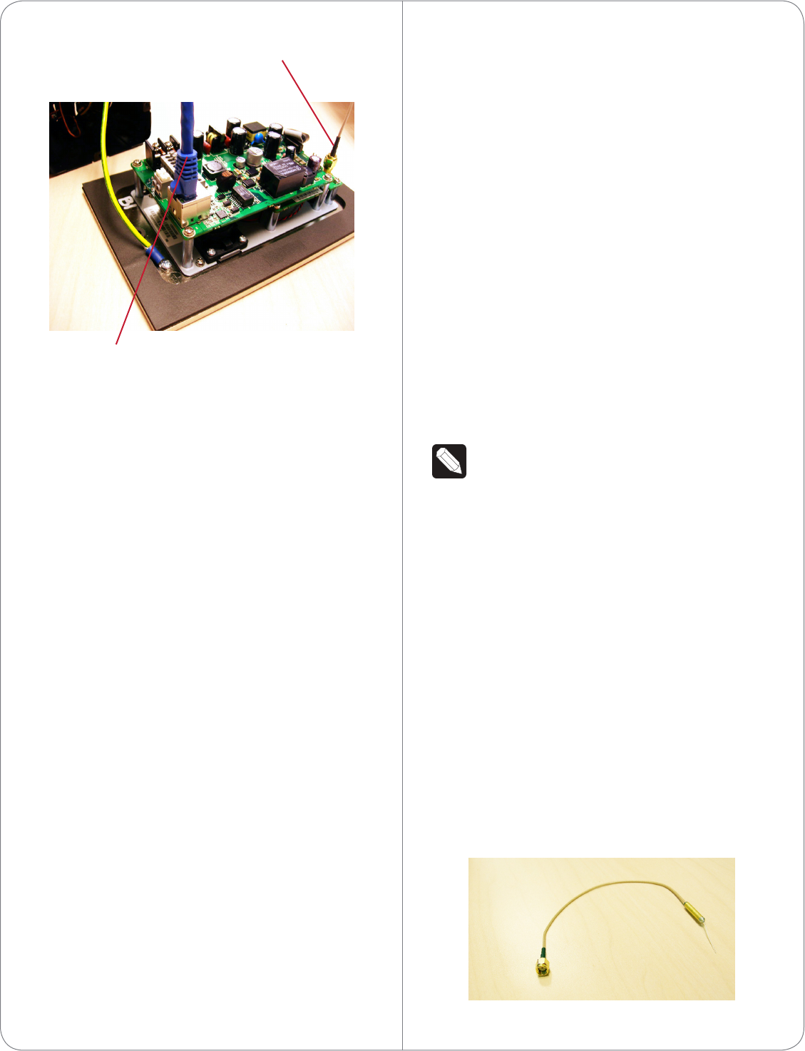
Figure 8. WiFi with PoE
Attach the Door Station
After the back box, all wiring, cables, and antennas
are installed, carefully insert the Door Station into the
back box and the wall:
1 Align the Door Station’s top and bottom screw
holes on the faceplate with the screw holes on
the back box.
2 Use the screws provided to attach the Door
Station to the back box.
3 To prevent future moisture and dust from getting
inside the Door Station, make sure the rubber
gasket on the inside panel of the Door Station
completely covers and seals the Door Station’s
faceplate against the back box.
Configure the Door Station
To configure the Door Station in Composer Pro:
1 Open Composer Pro.
2 Double-click the Door Station driver to add it to
a room in the project.
3 Identify the device to the project.
(WiFi only) For your convenience, the Door Station
driver includes a meter to check WiFi signal strength.
Use System Manager in Composer Pro to configure
the WiFi parameters. See the Composer Pro User
Guide for details.
Reset/Factory Restore the Door Station
To reset or factory restore the Door Station:
1 Unscrew the faceplate (top and bottom) and
pull the Door Station out from the back box just
enough to expose the Reset button (see Figure
2).
2 While powered press the Reset button on the
bottom of the Door Station to reset or restore
the Door Station.
• Quick press. Press to reset the Door Station.
• Long press. Press until the button on the
faceplate begins to blink rapidly. At that time, the
factory restore starts. This action restores the
Door Station to its factory default settings.
3 When you are finished, insert the Door Station
back into the back box and screw the faceplate
back on.
WiFi Antennas (Optional)
NOTE: Control4 does not recommend to install
the Door Station using WiFi. The best option is
to use Ethernet.
Two (2) types of WiFi antenna kits are available for
purchase: 26cm (dipole, best performance) or 3m
(when you need to install the wire further away from
the Door Station for a better WiFi signal).
• Antenna Kit—WiFi/ZigBee 2.4GHz, 26cm (C4-
AK-26cm, sold separately). Recommended for
walls that do not have thick concrete or metal.
See Figure 9 and “WiFi Antenna Kit Installation”
for details.
• Antenna Kit—WiFi/ZigBee 2.4GHz, 3m (C4-AK-
3M, sold separately). Extend the range when
walls have thick concrete or metal. See Figure 10
and “WiFi Antenna Kit Installation” for details.
Figure 9. 26cm Antenna Kit
7
WiFi Antenna
Ethernet and PoE Connection
8
Figure 10. 3m Antenna Kit
WiFi Antenna Kit Installation (Optional)
Before you install the antenna:
1 Make sure the Door Station is assembled.
2 Make sure the Door Station back box is installed
in the wall. See the Door Station Back Box
Installation Guide for details.
Antenna Kit—WiFi/ZigBee 2.4GHz, 26cm
(C4-AK-26cm)
1 Remove the antenna from its packaging.
2 Attach the antenna’s plug to the RSMA connector
on the Door Station (see Figure 11).
Figure 11. Antenna to RSMA Connector
3 Thread the other end of the antenna through the
back wall of the back box (see Figure 12).
Figure 12. Thread Antenna Through Back Box
4 Leave the other end of the antenna hanging
outside the back box. Adjust it vertically for the
best signal.
5 Carefully insert the Door Station into the back box
(see “Attach the Door Station”).
Antenna Kit— WiFi/ZigBee 2.4GHz, 3m (C4-AK-3M)
1 Attach the antenna’s plug to the RSMA connector
on the Door Station (see Figure 11).
2 Thread the other end of the antenna through the
back wall of the back box and through the wall as
needed (see Figure 12).
3 Carefully insert the Door Station into the back box
(see “Attach the Door Station”).
Contact and Relay Connections
You can connect devices to the contact ports or the
relay ports (see Figure 13).
CAUTION! Control4 does not support using
earth ground for Contacts as this could
damage the Door Station.
RSMA Connector
Antenna
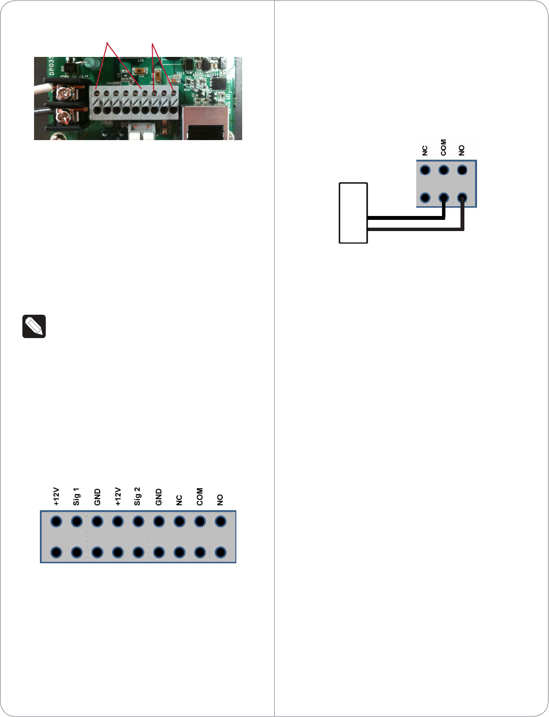
Figure 13. Contacts and Relays
Connect to a Port
The Door Station provides six (6) ports for use as two
(2) contact sets and one (1) relay (see Figure 14).
• Contact (2 sets). Terminal connector for one
(1) dry contact closure, logic input connection,
for gate control, etc. Provides power for small
devices (12 V), signal input (SIG), return path
(GND). The current, 100 mA, is shared across
both sets of contacts.
NOTE: Do not use contacts that are grounded.
The Door Station only supports non-grounded
contacts.
• Relay (1). Terminal connector for one (1)
normally closed or normally opened switchable
connection for doorbell control (see Figure 15) or
gate control. The set contains a connection for
Normally Opened (NO), Normally Closed (NC),
and Common (COM).
Figure 14. Contact/Relay Locations
1 To attach the wires to the contacts or relay, select
one of the large bottom-row holes (see Figure 13;
notice that the top row holes are smaller than the
bottom-row holes).
2 Using a small flat screwdriver, insert the
screwdriver into the slot on the small block that
sits between the two rows of holes adjacent to
the port and push down firmly. The block will
9
depress.
3 Insert the wire. Ensure that the wire inserts all the
way into the hole.
4 Release the screwdriver.
Example Wiring
Figure 15. Relay Port: Normally Open (e.g., Doorbell)
Troubleshooting
Boot Up
When the Door Station is booting up, if the button
blinks and does not stop after (3) minutes or longer,
there is a problem with the device and it will have to
be restored. See “Reset/Restore the Door Station”
later in this document.
Factory Restore
To restore the device to its default factory settings,
see “Reset/Restore the Door Station” later in this
document.
Security Best Practices
The Control4 Door Station – Exterior is the first
smart Control4 device designed to be installed on
the outside of a dwelling. The Door Station has
connections for relays (to open doors, gates, etc.)
and contacts. If installed without the proper security
precautions, unauthorized access to the Door Station
could provide access to Ethernet signals, Control4
signaling, and gate or door relays. Control4 advises
Control4 Dealers to be aware of these risks and take
all necessary precautions depending on each specific
installation you will be doing.
It is each Dealer’s sole responsibility to advise their
customer at each installation of any security risks
specific to such installation. Control4 makes no
Contacts Relays
claims, representations or warranties regarding the
security of this product and accepts no liability for
any security risk attendant to a specific installation.
1 The Door Station - Exterior ships standard with
security screws. Dealers are encouraged to
use these screws, or even substitute alternate
security screws per the Dealer’s or customer’s
preference. Screw size is metric M3.5x.6-30L.
2 Security gates or automatic doors should not
be connected to the relay in the Door Station
if mounted in an unsecured area; such relays
could be accessed in the event of a breach of
the device. Secure relay-driven devices should
be connected to a more secure relay controller
mounted behind a secure wall.
3 Security devices, for example numeric keypads,
should not be connected to the contact sensors
in the Door Station if mounted in an unsecured
area; such devices could be accessed in the event
of a breach of the device. Security-sensitive
devices should be connected to more secure
contacts mounted behind a secure wall.
4 Although the best video performance will be
enabled by Ethernet connectivity, unauthorized
access to the Door Station could provide
access to the dwelling’s Ethernet network and
corresponding personal data.
There are alternatives to mitigate this risk. The
Dealer should consider the following options:
• Running Control4 on an isolated LAN from PCs
on the network would limit exposure to personal
data.
• Running MAC address filtering on the router
or switch to force a hacker to spoof the Door
Station’s MAC address to gain access to the LAN.
• Configuring the Door Station as WiFi instead of
Ethernet would allow the Dealer to use robust
WiFi security protocols, for example, WPA.
NOTE: WiFi signals must be very strong and
stable to support Video Intercom.
• Routing the Ethernet cable to the Door Station
through a secure, managed switch to limit data
access from the Door Station.
10
Dealers should take time to assure they are not
creating an unforeseen security risk for the customer,
and any such risks should be discussed with the
customer prior to the installation.
Carefully consider with your customer any contacts
or relays before connecting them to the Door Station,
and what implications could arise if someone gained
access to the rear of the Door Station.
Also, think about what could happen if someone
gained access to the Ethernet cable, and take
necessary precautions to protect private customer
information unless your customer is willing to assume
these risks. Making available the proper security
protections to a customer for their residence is the
responsibility of the Control4 Installer.
Warnings
WARNING! To avoid bodily harm, understand
and follow these safety precautions before
operating this Door Station:
- Using worn-out or damaged power cords
may result in electric shock or fire.
- Always contact an authorized Control4
service provider for assistance if any repair or
adjustment is required.
Avertissement! Pour éviter des dommages
physiques, comprenez et suivez ces mesures
de sécurité avant d’actionner station de porte
Control4® sans fil:
- Utilisant usé ou endommagé les cordons de
secteur peuvent avoir comme conséquence
la décharge électrique ou le feu.
- Entrez en contact avec toujours un
fournisseur des services Control4® autorisé
pour l’aide si n’importe quelle réparation ou
ajustement est exigée.
IMPORTANT! Improper use or installation can
cause LOSS/DAMAGE OF PROPERTY.
Important! L’utilisation ou l’installation inexacte
peut causer LOSS/DAMAGE DE PROPRIÉTÉ.
©2012 Control4. All rights reserved. Control4, the Control4 logo, the Control4 iQ logo and the Control4 certified logo are registered trademarks or trademarks
of Control4 Corporation in the United States and/or other countries. All other names and brands may be claimed as the property of their respective owners.
control4.com | ™
IMPORTANT! Using this product in a manner
other than outlined in this document voids
your warranty. Further, Control4 is NOT liable
for any damage incurred with the misuse of
this product. See “Warranty.”
Important! Utilisant ce produit en quelque
sorte autre que décrit dans ce document vide
votre garantie. De plus, Control4 n’est pas
responsable d’aucun dommage encouru avec
l’abus de ce produit. Voyez que «Warranty.»
WARNING! Before you install the Door Station
switch o the circuit breaker or remove the
fuse from the fuse box.
AVERTISSEMENT! Pour l’endroit où vous
installez station de porte, coupez le disjoncteur
ou enlevez le fusible de la boîte de fusible.
IMPORTANT! Before you can complete these
instructions below, you must have a Door
Station back box installed according to the
documentation provided in the back box kit.
See “Accessories” for details.
Important! En coupant l’ouverture pour la
boîte de mur, ne coupez pas l’ouverture trop
grande. Soyez conservateur et agrandissez-
avec précaution la comme nécessaire. Voyez
que <<Accessories>>.
Regulatory/Safety Information
To review regulatory information for your particular
Control4 products, see the information located on
the Control4 website at: http://www.control4.com/
regulatory/.
Warranty
Limited 2-year Warranty. Go to http://www.control4.
com/warranty for details.
About This Document
Part number: 200-00243, Rev. C 6/11/2012
11

Regulatory Compliance & Safety Information for Contol4 Model C4-DSC-EN-XX.
Electrical Safety Advisory
Important Safety Information
Read the safety instructions before using this product.
1. Read these instructions.
2. Keep these instructions.
3. Heed all warnings.
4. Follow all instructions.
5. Do not use this apparatus near water.
6. Clean only with dry cloth.
7. Do not block any ventilation openings. Install in accordance with the manufacturer’s
instructions.
8. Do not install near any heat sources such as radiators, heat registers, stoves, or other
apparatus (including amplifiers) that produce heat.
9. Do not defeat the safety purpose of the polarized or grounding-type plug. A polarized
plug has two blades with one wider than the other. A grounding type plug has two blades
and a third grounding prong. The wide blade or the third prong is provided for your safety.
If the provided plug does not fit into your outlet, consult an electrician for replacement of
the obsolete outlet.
10. Protect the power cord from being walked on or pinched particularly at plugs,
convenience receptacles, and the point where they exit from the apparatus.
11. Only use attachments/accessories specified by the manufacturer.
12. Use only with the cart, stand, tripod, bracket, or table specified by the manufacturer, or
sold with the apparatus. When a cart is used, use caution when moving the
cart/apparatus combination to avoid injury from tip-over.
13. Unplug this apparatus during lightning storms or when unused for long periods of time.
This equipment uses AC power which can be subjected to electrical surges, typically
lightning transients which are very destructive to customer terminal equipment connected
to AC power sources. The warranty for this equipment does not cover damage caused
by electrical surge or lightning transients. To reduce the risk of this equipment becoming
damaged it is suggested that the customer consider installing a surge arrestor.
14. Refer all servicing to qualified service personnel. Servicing is required when the
apparatus has been damaged in any way, such as power-supply cord or plug is
damaged, liquid has been spilled or objects have fallen into the apparatus, the apparatus
has been exposed to rain or moisture, does not operate normally, or has been dropped.
15. Use the mains plug to disconnect the apparatus from the AC mains. The mains plug shall
remain readily operable.
16. To completely disconnect unit power from the AC mains, disconnect the unit’s power cord
from the mains socket. To reconnect power, plug the unit’s power cord into the mains
socket following all safety instructions and guidelines. The socket-outlet shall be installed
near the equipment and shall be easily accessible.
17. This product relies on the buildings installation for short-circuit (overcurrent) protection.
Ensure that the protective device is rated not greater than: 120 VAC, 20A or 240 VAC
10A.

18. CAUTION: As with all batteries, there is a risk of explosion or personal injury if the
battery is replaced by an incorrect type. Dispose of used battery according to the
instructions of the battery manufacturer and applicable environmental guidelines. Do not
open, puncture or incinerate the battery, or expose it to conducting materials, moisture,
liquid, fire or heat above 54° C or 130° F.
19. Never push objects of any kind into this product through cabinet slots as they may touch
dangerous voltage points or short out parts that could result in fire or electric shock.
20. This product can interfere with electrical equipment such as tape recorders, TV sets,
radios, computers and microwave ovens if placed in close proximity.
The lightning flash and arrow head within the triangle is a warning sign alerting
you of dangerous voltage inside the product
Caution: To reduce the risk of electric shock, do not remove cover (or back). No
user serviceable parts inside. Refer servicing to qualified service personnel.
The exclamation point within the triangle is a warning sign alerting you of
important instructions accompanying the product.
See marking on bottom / back of product
Warning!: To reduce the risk of electrical shock, do not expose this
apparatus to rain or moisture
AVERTISSEMENT! Pour réduire le risque de choc électrique,
n'exposez pas cet appareil à la pluie ou à l'humidité.
WARNUNG! Um das Risiko des elektrischen Schlages zu verringern,
setzen Sie diesen Apparat nicht Regen oder Feuchtigkeit aus.
Save these instructions
Compliance of this equipment is confirmed by the following label that is placed on the equipment:
USA & Canada Compliance
FCC Part 15, Subpart B / ICES-003Unintentional Emissions Interference Statement
This equipment has been tested and found to comply with the limits for a Class B digital device,
pursuant to Part 15 of the FCC rules and Industry Canada ICES-003. These limits are designed
to provide reasonable protection against harmful interference when the equipment is operated in
a residential installation. This equipment generates uses and can radiate radio frequency energy

and, if not installed and used in accordance with the instructions, may cause harmful interference
to radio communications. However, there is no guarantee that interference will not occur in a
particular installation. If this equipment does cause harmful interference to radio or television
reception, which can be determined by turning the equipment off and on, the user is encouraged
to try to correct the interference by one or more of the following measures:
Reorient or relocate the receiving antenna.
Increase the separation between the equipment and receiver.
Connect the equipment into an outlet on a circuit different from that to which the receiver
is connected.
Consult the dealer or an experienced radio/TV technician for help.
This device complies with part 15 of the FCC rules and Industry Canada ICES-003. Operation is
subject to the following two conditions: (1) This device may not cause harmful interference, and
(2) this device must accept any interference received, including interference that may cause
undesired operation.
Le présent appareil est conforme aux CNR d’Industrie Canada applicables aux appareils radio
exempts de licence. L’exploitation est autorisée aux deux conditions suivantes : (1) l’appareil ne
doit pas produire de brouillage, et (2) l’utilisateur de l’appareil doit accepter tout brouillage
radioélectrique subi, même si le brouillage est susceptible d’en compromettre le fonctionnement.
IMPORTANT! Any changes or modifications not expressly approved by the party responsible for
compliance could void the user’s authority to operate this equipment.
IMPORTANT! Tous les changements ou modifications pas expressément approuvés par la partie
responsable de la conformité ont pu vider l’autorité de l’utilisateur pour actionner cet équipement.
Ferrite clamp installation. When installing a Control4® C4-DSC-EN Door Station, also install the
enclosed ferrite clamp as described in this document.
Install the ferrite clamp on the Ethernet cable no farther than 6 inches from the Ethernet jack
inside of the back box.
Compliance of this equipment is confirmed by the following label that is placed on the equipment:
FCC Part 15, Subpart C / RSS-210 Intentional Emissions Interference Statement
Compliance of this equipment is confirmed by the following certification numbers that are placed
on the equipment:
Notice: The term “FCC ID:” and “IC” before the certification number signifies that FCC and
Industry Canada technical specifications were met.
FCC ID: R33C4DSC
IC: 7848A-C4DSC

This equipment must be installed by qualified professionals or contractors in accordance with
FCC Part 15.203 & IC RSS-210, Antenna Requirements. Do not use any antenna other than the
one provided with the unit.
RF Radiation Exposure Statement
This equipment complies with the FCC/IC radiation exposure limits set fourth for portable
transmitting devices operation in an uncontrolled environment. End users must follow the specific
operating instructions to satisfy RF exposure compliance.
The equipment should only be used or installed at locations where there is normally at
least a 20cm separation between the antenna and all persons.
This transmitter must not be co-located or operation in conjunction with any other
antenna or transmitter.
Any changes or modifications not expressly approved by the party responsible for
compliance could void the user’s authority to operate this equipment.
European Compliance
Conformity of the equipment with the guidelines below is attested by the application of the CE
mark.
CE Declaration of Conformity
Manufacturer’s Name: CONTROL4 CORPORATION
Manufacturer’s Address: 11734 S. ELECTION ROAD SUITE 200
SALT LAKE CITY
UT 84020 USA
EU Representative Name: CONTROL4 EMEA LIMITED
EU Representative Address: UNIT3, GREEN PARK BUSINESS CENTRE
SULTON-ON-THE FOREST
YORK YO61 IET, UNITED KINGDOM
Product Name(s): Doorbell Station
Brand: Contol4
Model(s): C4-DSC-EN-XX
Product Standard(s) to which Conformity of the Council Directive(s) is declared:
EMC - 2004/108/EC “Electromagnetic Compatibility (EMC) Directive”:
(Emissions) EN 55022:2010, (Immunity) EN 55024:1998, EN 301 489-1:2008, EN 301 489-
17:2009, EN 61000-3-2:2004 & EN 61000-3-3:2002
Safety – 206/95/EC “Low Voltage Directive (LVD)”:
EN 60950-1:2006 (2nd Edition) .

Telecom & Radio - 1999/5/EC Radio equipment and Telecommunications Terminal
Equipment (R&TTE) Directive:
EN 300 328 V1.7.1 (2006-10)
RoHS - 2002/95/EC Restriction of the Use of certain Hazardous Substances in Electrical
and Electronic Equipment (EEE) & WEEE - 2002/96/EC Waste of Electrical and Electronic
Equipment (EEE).
We, the undersigned, hereby declare that the equipment specified above conforms to the above
directives and standards. Date of Issue: July 24, 2012
Legal Representative
Signature
Roger Midgley
Sr. Regulatory Compliance Engineer
National Restrictions
This product may be used in all EU countries (and other countries following the EU directive
1999/5/EC) without any limitation except for the countries mentioned below:
Ce produit peut être utilisé dans tous les pays de l'UE (et dans tous les pays ayant transposés la
directive 1999/5/CE) sans aucune limitation, excepté pour les pays mentionnés ci-dessous:
Questo prodotto è utilizzabile in tutte i paesi EU (ed in tutti gli altri paesi che seguono le direttive
EU 1999/5/EC) senza nessuna limitazione, eccetto per i paesii menzionati di seguito:
Das Produkt kann in allen EU Staaten ohne Einschränkungen eingesetzt werden (sowie in
anderen Staaten die der EU Direktive 1999/5/CE folgen) mit Außnahme der folgenden
aufgeführten Staaten:
France
In case the product is used outdoors, the output power is restricted in some parts of the band.
See Table 1 below or check http://www.arcep.fr/ for more details.
Dans la cas d'une utilisation en extérieur, la puissance de sortie est limitée pour certaines parties
de la bande. Voir la table ci-dessous ou visitez http://www.arcep.fr/ pour de plus amples details
Table 1 Applicable Power Levels in France
Location Frequency Range (MHz) Power (EIRP)
Indoor (No restrictions) 2400-2483.5 100 mW (20 dBm)
Outdoor 2400-2454
2454-2483.5 100 mW (20 dBm)
10 mW (10 dBm)
Recycling
Control4 understands that a commitment to the environment is essential for a health life and
sustainable growth for future generations. We are committed to supporting the environmental
standards, laws, and directives that have been put in place by various communities and countries
that deal with concerns for the environment. This commitment is represented by combining
technological innovation with sound environmental business decisions.
WEEE Compliance
Control4 is committed to meeting all requirements of the Waste Electrical and Electronic
Equipment (WEEE) directive (2002/96/EC). The WEEE directive requires the manufacturers of
electrical and electronic equipment who sell in EU countries: (1) label their equipment to notify
customers that it needs to be recycled, and (2) provide a way for their products to be
appropriately disposed of or recycled at the end of their product lifespan. For collection or
recycling of Control4 products, please contact your local Control4 representative or dealer.
Australia / New Zealand Compliance
Compliance of this equipment is confirmed by the following label that is placed on the equipment:
About this Document
Copyright © 2012 Control4 Corporation. All rights reserved. Control4 and the Control4 logo are
registered trademarks or trademarks of Control4 Corporation in the United States and/or other countries.
Part Number 200-00291 Rev A, 7/24/2012