Snap One C4EA3V2 System controller User Manual Control4 EA 3 V2 Installation Guide
Control4 System controller Control4 EA 3 V2 Installation Guide
Snap One >
User Manual
Supported models
• C4-EA3 Entertainment and Automation Controller, 3 Zone
• C4-EA3-V2 Entertainment and Automation Controller, 3 Zone, V2
Introduction
The versatile Control4 EA-3 Entertainment and Automation Controller is
the perfect fusion of multi-room, high-resolution audio and smart home
automation for small to mid-size homes.
Powered by a next-generation multi-core processor, the EA-3 delivers
a new level of speed and performance for instantaneous, interactive
on-screen access to all the systems in the home. A built-in music server
with three audio outputs delivers high-resolution audio throughout
the home from your local music library, popular streaming music
services, and AirPlay-enabled devices using native Control4 ShairBridge
technology.
The EA-3 includes a variety of I/O to automate audio and video,
lighting, climate control, door locks, and other devices controlled by
IP, infrared (IR), serial, and ZigBee. With PoE+ for power, a port for
Ethernet out, and an optional mounting bracket, the compact form
factor of the EA-3 makes it easy to install behind any TV or projector.
Box contents
The following items are included in the box:
• EA-3 controller
• AC power cord
• IR emitters (6)
• External antennas (1 EA-3 V2, 2 EA-3 V1)
• Terminal block for contacts and relays
Accessories sold separately
• Control4 3.5 mm-to-DB9 Serial Cable (C4-CBL3.5-DB9B)
• 1U Rack-Mount Kit, Single EA-3 Controller (C4-EA3RMK1-BL)
• 1U Rack-Mount Kit, Dual EA-3 Controllers (C4-EA3RMK2-BL)
• EA-3 Wall-Mount Bracket (C4-WMEA3)
• Dual-Band WiFi USB Adapter (C4-USBWIFI or C4-USBWIFI-1)
Warnings
Caution! To reduce the risk of electrical shock, do not expose
this apparatus to rain or moisture.
Avertissement ! Pour réduire le risque de choc électrique,
n’exposez pas cet appareil à la pluie ou à l’humidité.
Caution! In an over-current condition on USB or contact
output the software disables the output. If the attached USB
device or contact sensor does not appear to power on, remove
the device from the controller.
Avertissement ! Dans une condition de surintensité sur USB ou
sortie de contact le logiciel désactive sortie. Si le périphérique
USB ou le capteur de contact connecté ne semble pas
s’allumer, retirez le périphérique du contrôleur.
Requirements and specifications
Note: We recommend using Ethernet instead of WiFi for the
best network connectivity.
Note: The Ethernet or WiFi network should be installed before
you install the EA-3 Controller.
Note: The EA-3 V2 requires OS 2.10.2 or higher. The EA-3 V1
requires OS 2.8.1 or higher.
Composer Pro is required to configure this device. See the Composer
Pro User Guide (ctrl4.co/cpro-ug) for details.
Specifications
Inputs / outputs
Video out 1 video out—1 HDMI
Video HDMI 1.4 output; HD 1080p, 50-60 Hz
Audio out 3 audio outputs—1 HDMI, 1 stereo analog (3.5 mm),
1 digital coax
Audio in 2 network-encoded audio inputs—1 stereo analog
(3.5 mm), 1 digital coax
Audio delay on audio in Up to 3.5 seconds, depending on network conditions
Audio playback formats AAC, AIFF, ALAC, FLAC, M4A, MP2, MP3, MP4/M4A,
Ogg Vorbis, PCM, WAV, WMA
High-resolution audio playback Up to 192 kHz / 24 bit
Advanced audio subsystem Dedicated audio signal processor
Audio system controls (analog
only)
10-band graphic equalizer, input gain, output gain,
loudness, tone controls, balance
Signal-to-noise ratio <-110 dBFS
Total harmonic distortion 0.0015 (-96.5 dB)
Network
Ethernet 10/100/1000BaseT compatible (required for
controller setup). PoE+ supported.
Power over Ethernet 802.3at-2009 (PoE+) / 25.5W
Built-in Ethernet switch 1 Ethernet/PoE in + 1 Ethernet switch port
WiFi Internal Dual-Band Wireless-N (EA-3 V1)
(2.4GHz, 5GHz, 802.11n/g/b)
Optional Dual-Band WiFi USB Adapter (EA-3 V2)
(2.4 GHz, 5 Ghz, 802.11ac/b/g/n/a)
WiFi security WPA/WPA2
WiFi antenna External reverse SMA connector (EA-3 V1 only);
optional WiFi adapter on the EA-3 V2
ZigBee Pro 802.15.4
ZigBee antenna External reverse SMA connector
USB port 1 USB 2.0 port—500mA minimum
Control
IR OUT 6 IR out—5V 27mA max output
1 IR blaster—front
IR capture 1 IR receiver—front; 20-60 KHz
SERIAL OUT 3 serial out (shared with IR out 1-3)
Contact 1 contact sensor—2V-30VDC input,
12VDC 125mA maximum output
Relay 1 relay—AC: 36V, 2A maximum voltage across relay;
DC: 24V, 2A maximum voltage across relay
Power
Power requirements 100-240 VAC, 60/50Hz or PoE+
Power consumption Max: 18W, 61 BTUs/hour
Idle: 9W, 30 BTUs/hour
Other
Operating temperature 32˚F ~ 104˚F (0˚C ~ 40˚C)
Storage temperature 4˚F ~ 158˚F (-20˚C ~ 70˚C)
Fan dB level Max: 35 dB
Dimensions (H × W × D) 8.75 × 5.875 × 1.25" (221 × 149 × 31 mm)
Weight 1.60 lbs (0.74 kg)
Shipping weight 2.75 lbs (1.26 kg)
Installing the controller
To install the controller:
1 Ensure that the home network is in place before starting system
setup. The controller requires a network connection—Ethernet
(recommended) or WiFi—to use all of the features as designed.
When connected, the controller can access web-based media
databases, communicate with other IP devices in the home, and
access Control4 system updates.
2 Mount the controller behind a TV, on a wall, placed in a rack, or
stacked on a shelf. See “Mounting the controller behind a TV or on
the wall” below if mounting the controller on a wall or behind a TV.
3 Attach antennas to the WIFI and ZIGBEE antenna connectors and
for an EA-3 V2 controller, connect the optional WiFi USB Adapter
to the USB port if WiFi connectivity is needed.
4 Connect the controller to the network.
• Ethernet—To connect using an Ethernet connection, plug the data
cable from the home network connection into the controller’s RJ-
45 port (labeled “ETHERNET/POE”) and the network port on the
wall or at the network switch. An additional Ethernet-connected
device can be connected to the Ethernet Out RJ-45 port.
Note: If using PoE+ to power the controller, make all
connections prior to plugging in the PoE injector or switch.
• WiFi—To connect using WiFi, first connect the controller to
Ethernet, and then use Composer Pro System Manager to
reconfigure the controller for WiFi.
Important: Do not install your EA controller on a
172.18.xxx.xxx subnet.
5 Connect system devices such as IR and serial devices as described
in “Connect the IR ports/serial ports” and “Set up IR emitters.”
6 Set up any external storage devices as described in “Setting up
external storage devices” in this document.
7 Connect the power cord to the controller’s power port and then
into an electrical outlet, or for a PoE connection, power on the
PoE+-enabled network switch or PoE+ injector.
Mounting the controller behind a TV or on the wall
Using the optional Wall-Mount Bracket (C4-WMEA3), the EA-3 can
easily be mounted behind a TV, on the wall using a 1- or 2-gang wall
box, or mounted directly on the wall. See the EA-3 Wall-Mount Bracket
Installation Guide (ctrl4.co/ea-wmb) for details.
Pluggable terminal block connectors
For the contact and relay ports, the EA-3 makes use of terminal block
connectors which are removable plastic parts that screw down to
secure individual wires (included).
To connect a device to the terminal block:
1 Insert one of the wires required for your device into the appropriate
opening in the pluggable terminal block you reserved for that
device (see Figure 3).
2 Insert the wire into the appropriate terminal connection and use a
small, flat-blade screwdriver to tighten the screw and secure the
wire.
Example: If you add a motion sensor (see Figure 5), connect
its wires to the following contact openings:
Power input to +12V
Output signal to SIG
Ground connector to GND
Tip: To connect a dry contact closure device, such as a
doorbell button, connect the wires from the button to
+12V (Power) and SIG (Signal).
Control4 EA-3 Controller
Installation Guide
Additional resources
The following resources are available for more support.
• Control4 Knowledgebase: kb.control4.com and Dealer Forums:
forums.control4.com
• Control4 Technical Support
• Control4 website: www.control4.com
• Composer Pro documentation in online help or PDF format available
on the Dealer Portal under Support: ctrl4.co/docs
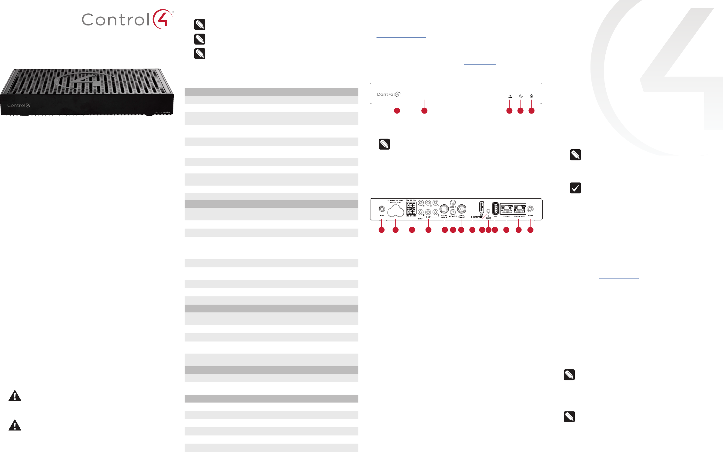
Front view
A Data LED—The LED indicates that the controller is streaming audio.
B IR window—IR blaster and IR receiver for learning IR codes.
C Caution LED—This LED shows solid red, then blinks blue during the
boot process.
Note: The Caution LED flashes orange during the factory
restore process. See “Reset to factory settings” in this
document.
D Link LED—The blue LED indicates that the controller has been
identified in a Control4 Composer project and is communicating with
Director.
E Power LED—The blue LED indicates that AC power is connected. The
controller turns on immediately after power is applied to it.
Back view
A WIFI—Reverse SMA connector for WiFi antenna (EA-3 V1 only).
B Power plug port—AC power receptacle for an IEC 60320-C5 power
cord.
C Contact/Relay port—Connect one relay device and one contact
sensor device to the terminal block connector. Relay connections are
COM, NC (normally closed), and NO (normally open). Contact sensor
connections are +12, SIG (signal), and GND (ground).
D Serial and IR OUT—3.5 mm jacks for up to six IR emitters or for a
combination of IR emitters and serial devices. Ports 1, 2, and 3 can
be configured independently for serial control or for IR control. See
“Connect IR/serial ports” in this document for more information.
E DIGITAL COAX IN—Allows audio to be shared over the local network
to other Control4 devices.
F AUDIO IN and OUT—Stereo audio input and output ports (3.5 mm
stereo audio jack). Allows audio to be shared (AUDIO IN) over the
local network to other Control4 devices. Outputs audio (AUDIO
OUT) shared from other Control4 devices or from digital audio
sources (local media or digital streaming services such as TuneIn).
G DIGITAL COAX OUT—Outputs audio (AUDIO OUT) shared from
other Control4 devices or from digital audio sources (local media or
digital streaming services such as TuneIn).
H HDMI OUT—An HDMI port to display navigation menus. Also an
audio out over HDMI.
I ID button—Button to identify the device in Composer Pro. The ID
button on the EA-3 V2 is also an LED that displays feedback useful
during a factory restore.
J FACTORY RESTORE—Used to restore the controller to its factory
defaults.
K USB—One port for an external USB drive, or, on an EA-3 V2, the
optional Dual-Band WiFi USB Adapter. See “Setting up external
storage devices” in this document.
L Ethernet—Ethernet port that can be used as a network switch to
connect another local Ethernet device to the network.
M Ethernet/POE—RJ-45 jack for a 10/100/1000 BaseT Ethernet
connection. Use this port as the ‘uplink port’ to your local network. If
using PoE+ to power the controller, this port must be used.
N ZIGBEE—Reverse SMA connector for ZigBee antenna.
A B C D E
A B C D E F G H I KJ L N
M
control4.com | 888.400.4070
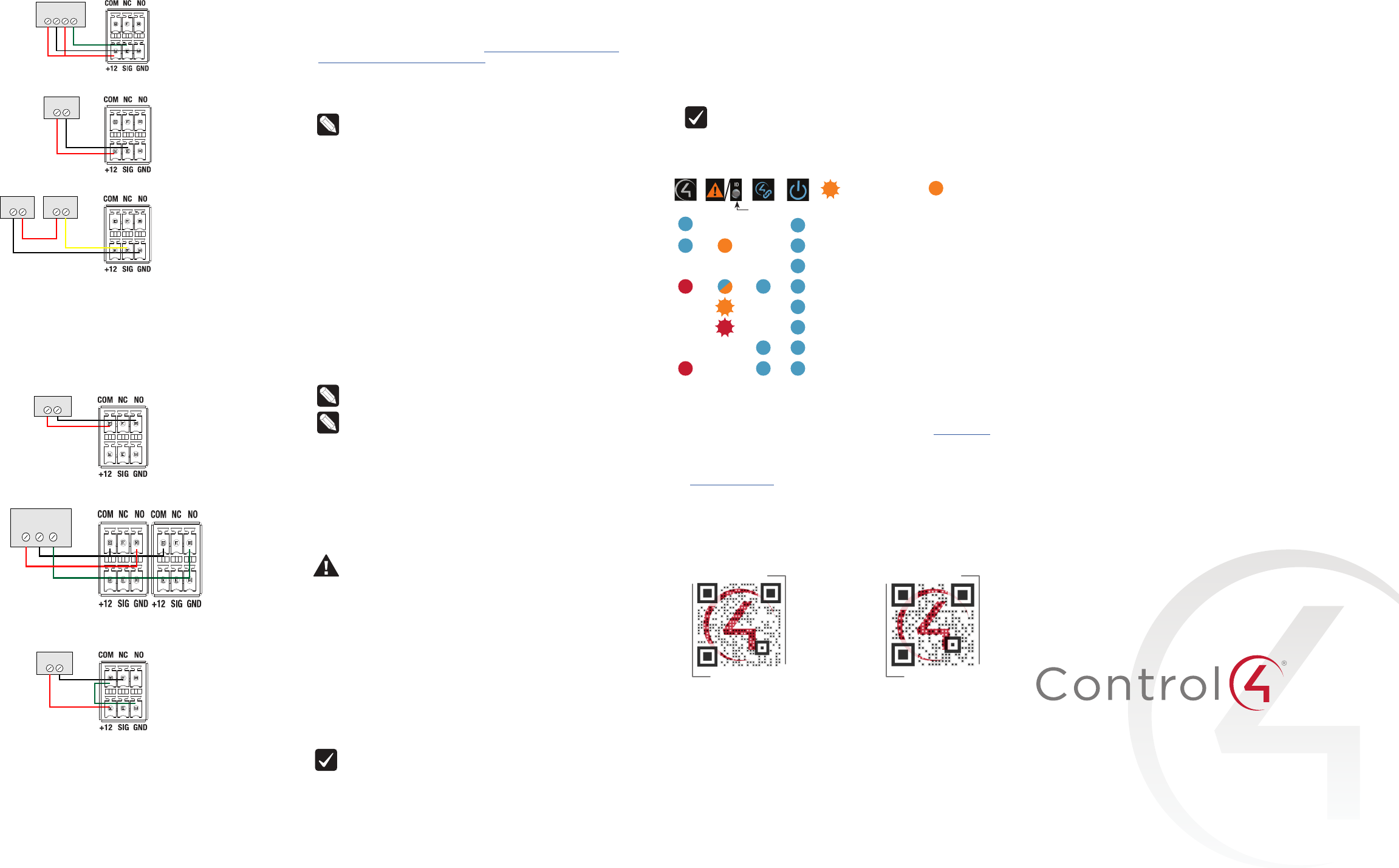
Connecting the contact port
The EA-3 provides one contact port on the included pluggable terminal
block (+12, SIG, GRD). See the examples below to learn how to connect
various devices to the contact port.
Wire the contact to a sensor that also needs power (Motion sensor)
Wire the contact to a dry contact sensor (Door contact sensor)
Wire the contact to an externally powered sensor (Driveway sensor)
Connecting the relay port
The EA-3 provides one relay port on the included pluggable terminal
block. See the examples below to learn now to connect various devices
to the relay port.
Wire the relay to a single-relay device, normally open (Fireplace)
Wire the relay to a dual-relay device (Blinds)
Wire the relay with power from the contact, normally closed (Amplifier trigger)
Motion Sensor
+12V 0V COM NO
Dry Contact
Driveway
Sensor
External
12V Power
Fireplace
Dual-Relay Blind
UP COM DOWN
Relay 1 Relay 2
12V Trigger
Connecting the IR ports/serial ports (optional)
The controller provides six IR ports. Ports 1, 2, and 3 can be
reconfigured independently for serial communication. If not used for
serial, they can be used for IR. Connect a serial device to the controller
using the Control4 3.5 mm-to-DB9 Serial Cable (C4-CBL3.5-DB9B, sold
separately).
1 The serial ports support many dierent baud rates (acceptable
range: 1200 to 115200 baud for odd and even parity). The serial
ports do not support hardware flow control.
2 See Knowledgebase article #268 (https://dealer.control4.com/
dealer/knowledgebase/article/268) for pinout diagrams.
3 To configure a port for serial or IR, make the appropriate
connections in your project using Composer Pro. See the Composer
Pro User Guide for details.
Note: The serial ports can be configured as straight-through or
null with Composer Pro. Serial ports by default are configured
straight-through and can be changed in Composer by
selecting the option Enable Null-Modem Serial Port (1/2/3).
Setting up IR emitters
Your system may contain third-party products that are controlled
through IR commands.
1 Connect one of the included IR emitters to an IR OUT port on the
controller.
2 Place the stick-on emitter end onto the IR receiver on the Blu-
ray player, TV, or other target device to drive IR signals from the
controller to the targets.
Setting up external storage devices (optional)
You can store and access media from an external storage device, for
example, a network hard drive or USB memory device, by connecting
the USB drive to the USB port and configuring or scanning the media in
Composer Pro.
Note: We support only externally powered USB drives or solid
state USB sticks. Self-powered USB drives are not supported.
Note: When using USB storage devices on an EA-3 controller,
you can use only one partition with a 2 TB maximum size. This
limitation also applies to the USB storage on other controllers.
Composer Pro driver information
Use Auto Discovery and SDDP to add the driver to the Composer
project. See the Composer Pro User Guide for details.
Troubleshooting
Reset to factory settings
Caution! The factory restore process will remove the
Composer project. Back up the project with Composer Pro
before you start the factory restore process
To restore the controller to the factory default image:
1 Insert a straightened paper clip into the small hole on the back of
the controller labeled FACTORY RESTORE.
2 Press and continue to hold the FACTORY RESTORE button, the
controller resets and the caution LED turns solid red.
3 Hold the button until the Caution LED flashes double orange. This
should take five to seven seconds. The Caution LED flashes orange
while the factory restore is running. When complete, the Caution
LED turns o and the device power cycles one more time to
complete the factory restore process.
Note: On an EA-3 V2 controller, the ID button is also an LED
that provides the same feedback as the Caution LED on the
front of the controller.
Power cycle the controller
1 Press and hold the ID button for five seconds. The controller turns
o and back on.
Reset the network settings
To reset the controller network settings to the default:
1 Disconnect power to the controller.
2 While pressing and holding the ID button on the back of the
controller, reconnect power to the controller.
3 Hold the ID button until the Caution LED (rear ID LED) appears
solid orange and the Link and Power LEDs are solid blue, and then
immediately release the button.
Note: In OS 2.10.1 and lower, the Caution LED appears solid
blue during the network reset check. After updating to
OS 2.10.2 and higher, the Caution LED appears orange during
the network reset check.
LED status information
Just powered on
Bootloader loaded
Kernel loaded
Network reset check
Factory restore underway
Factory restore fail
Connected to Director
Playing audio
Regulatory/Safety information
To review regulatory information for your particular Control4 products,
see the information located on the Control4 website at ctrl4.co/reg.
Warranty
Visit ctrl4.co/warranty for details.
More help
For the latest version of this document and to view additional materials,
open the URL below or scan the QR code on a device that can view
PDFs.
Data Caution Link Power
—Flashing LED —Solid LED
on EA-3 V2 only
MOST RECENT VERSION
ctrl4.co/ea3-ig
MORE INFO ON EA CONTROLLERS
ctrl4.co/ea
200-00381-B
2018-05-09 DH
Copyright ©2018, Control4 Corporation. All rights reserved. Control4, the Control4 logo,
the 4-ball logo, 4Sight, Control4 My Home, and Mockupancy are registered trademarks
or trademarks of Control4 Corporation in the United States and/or other countries. All
other names and brands may be claimed as the property of their respective owners. All
specifications subject to change without notice. B

Regulatory Compliance & Safety Information for Control4 Model C4-EA3-V2
Electrical Safety Advisory
Sécurité électrique consultatif
Important Safety Information
Informations de sécurité importantes
Read the safety instructions before using this product.
Lisez les consignes de sécurité avant d'utiliser ce produit.
1. Read these instructions.
1. Lisez ces instructions.
2. Keep these instructions.
2. Conservez ces instructions.
3. Heed all warnings.
3. Respectez tous les avertissements.
4. Follow all instructions.
4. Suivez toutes les instructions.
5. Do not use this apparatus near water.
5. Ne pas utiliser cet appareil près de l'eau.
6. Clean only with dry cloth.
6. Nettoyez-le uniquement avec un chiffon sec.
7. Do not block any ventilation openings. Install in accordance with the manufacturer’s
instructions.
7. Ne pas bloquer les ouvertures de ventilation. Installer conformément aux instructions du
fabricant.
8. Do not install near any heat sources such as radiators, heat registers, stoves, or other
apparatus (including amplifiers) that produce heat.
8. Ne pas installer près de sources de chaleur telles que des radiateurs, registres de
chaleur, poêles, ou autres appareils (incluant les amplificateurs) qui produisent de la
chaleur.
9. Do not defeat the safety purpose of the polarized or grounding-type plug. A polarized
plug has two blades with one wider than the other. A grounding type plug has two blades
and a third grounding prong. The wide blade or the third prong is provided for your safety.
If the provided plug does not fit into your outlet, consult an electrician for replacement of
the obsolete outlet.
9. Ne pas contourner le dispositif de sécurité de la fiche polarisée ou de mise à la terre. Une
fiche polarisée possède deux lames dont une plus large que l'autre. Une fiche de terre a
deux lames et une troisième broche de terre. La lame large ou la troisième broche est
fournie pour votre sécurité. Si la fiche fournie ne s'adapte pas à votre prise, consultez un
électricien pour le remplacement de la prise obsolète.

10. Protect the power cord from being walked on or pinched particularly at plugs,
convenience receptacles, and the point where they exit from the apparatus.
10. Protégez le cordon d'alimentation ne soit piétiné ou pincé, en particulier au niveau des
fiches, des prises et au point où il sort de l'appareil.
11. Only use attachments/accessories specified by the manufacturer.
11. Utilisez uniquement des fixations / accessoires spécifiés par le fabricant.
12. Use only with the cart, stand, tripod, bracket, or table specified by the manufacturer, or
sold with the apparatus. When a cart is used, use caution when moving the
cart/apparatus combination to avoid injury from tip-over.
12. Utilisez uniquement avec le chariot, le socle, le trépied, le support ou la table spécifiés
par le fabricant ou vendu avec l'appareil. Lorsque vous utilisez un chariot, soyez prudent
lorsque vous déplacez l'ensemble chariot / appareil pour éviter des blessures dues au
renversement.
13. Unplug this apparatus during lightning storms or when unused for long periods of time.
13. Débranchez cet appareil pendant les orages ou lorsqu'il n'est pas utilisé pendant de
longues périodes de temps.
14. Refer all servicing to qualified service personnel. Servicing is required when the
apparatus has been damaged in any way, such as power-supply cord or plug is
damaged, liquid has been spilled or objects have fallen into the apparatus, the apparatus
has been exposed to rain or moisture, does not operate normally, or has been dropped.
14. Confiez toutes les réparations à un personnel qualifié. Une réparation est nécessaire
lorsque l'appareil a été endommagé de quelque façon que ce soit le cordon
d'alimentation ou la fiche est endommagé, du liquide a été renversé ou si des objets sont
tombés dans l'appareil, l'appareil a été exposé à la pluie ou à l'humidité, ne fonctionne
pas normalement , ou s'il est tombé.
15. This equipment uses AC power which can be subjected to electrical surges, typically
lightning transients which are very destructive to customer terminal equipment connected
to AC power sources. The warranty for this equipment does not cover damage caused
by electrical surge or lightning transients. To reduce the risk of this equipment becoming
damaged it is suggested that the customer consider installing a surge arrestor.
15. Cet équipement utilise la puissance AC qui peuvent être soumis à des surtensions
électriques, la foudre généralement transitoires qui sont très destructives envers les
équipements terminaux connectés à des sources d'alimentation CA. La garantie de cet
appareil ne couvre pas les dommages causés par les surtensions électriques ou
transitoires de foudre. Pour réduire le risque de cet équipement devient endommagé, il
est suggéré que le client envisager l'installation d'un limiteur de surtension.
16. To completely disconnect unit power from the AC mains, remove the power cord from the
appliance coupler and/or turn off the circuit breaker. To reconnect power, turn on the
circuit breaker following all safety instructions and guidelines. The circuit breaker shall
remain readily accessible.
16. Pour débrancher complètement l'alimentation secteur du réseau secteur, retirez le cordon
d'alimentation du coupleur de l'appareil et / ou éteignez le disjoncteur. Pour reconnecter
l'alimentation, allumez le disjoncteur en suivant toutes les consignes et consignes de
sécurité. Le disjoncteur doit être facilement accessible.
17. This product relies on the buildings installation for short-circuit (overcurrent) protection.
Ensure that the protective device is rated not greater than: 20A.
17. Ce produit repose sur l'installation des bâtiments pour les courts-circuits (surintensité) de
protection. Assurez-vous que le dispositif de protection est assignée ne dépassant pas:
20A.
18. CAUTION: As with all batteries, there is a risk of explosion or personal injury if the
battery is replaced by an incorrect type. Dispose of used battery according to the
instructions of the battery manufacturer and applicable environmental guidelines. Do not
open, puncture or incinerate the battery, or expose it to conducting materials, moisture,
liquid, fire or heat above 54° C or 130° F.
18. ATTENTION: Comme avec toutes les batteries, il ya un risque d'explosion ou de blessure
si la batterie est remplacée par un type incorrect. Éliminez les batteries usagées selon
les instructions du fabricant de la batterie et applicables des directives
environnementales. Ne pas ouvrir, percer ou incinérer la batterie, ou de l'exposer à des
matériaux conducteurs, de l'humidité, du liquide, un incendie ou une température
supérieure à 54 ° C ou 130 ° F.
19. Never push objects of any kind into this product through cabinet slots as they may touch
dangerous voltage points or short out parts that could result in fire or electric shock.
19. N'introduisez jamais d'objets d'aucune sorte dans ce produit à travers les fentes du
boîtier car ils pourraient toucher des points de tension dangereux ou court-circuiter des
pièces qui pourraient entraîner un incendie ou un choc électrique.
20. This product can interfere with electrical equipment such as tape recorders, TV sets,
radios, computers and microwave ovens if placed in close proximity.
20. Ce produit peut interférer avec des appareils électriques tels que les magnétophones,
téléviseurs, radios, ordinateurs et fours à micro-ondes si placés à proximité.
The lightning flash and arrow head within the triangle is a warning sign alerting
you of dangerous voltage inside the product
L'éclair et la flèche dans le triangle est un signe d'alerte pour vous avertir d'une
tension dangereuse à l'intérieur du produit
Caution: To reduce the risk of electric shock, do not remove cover (or back). No
user serviceable parts inside. Refer servicing to qualified service personnel.
Attention: Pour réduire le risque de choc électrique, ne pas retirer le couvercle
(ou l'arrière). Aucune pièce réparable par l'utilisateur. Confiez l'entretien à un
personnel qualifié.
The exclamation point within the triangle is a warning sign alerting you of
important instructions accompanying the product.
Le point d'exclamation dans un triangle est un signe d'avertissement vous
signale des instructions importantes accompagnant le produit.
See marking on bottom / back of product
Voir le marquage sur les bas / dos du produit
Warning!: To reduce the risk of electrical shock, do not expose this
apparatus to rain or moisture
AVERTISSEMENT! Pour réduire le risque de choc électrique,
n'exposez pas cet appareil à la pluie ou à l'humidité.

Save these instructions
Conservez ces instructions
Compliance of this equipment is confirmed by the following label that is placed on the equipment:
Conformité de cet appareil est confirmé par le symbole suivant qui est placé sur l'équipement:
USA & Canada Compliance
FCC Part 15, Subpart B Unintentional Emissions Interference Statement
This equipment has been tested and found to comply with the limits for a Class B digital device,
pursuant to Part 15 of the FCC rules. These limits are designed to provide reasonable protection
against harmful interference when the equipment is operated in a residential installation. This
equipment generates uses and can radiate radio frequency energy and, if not installed and used
in accordance with the instructions, may cause harmful interference to radio communications.
However, there is no guarantee that interference will not occur in a particular installation. If this
equipment does cause harmful interference to radio or television reception, which can be
determined by turning the equipment off and on, the user is encouraged to try to correct the
interference by one or more of the following measures:
• Reorient or relocate the receiving antenna.
• Increase the separation between the equipment and receiver.
• Connect the equipment into an outlet on a circuit different from that to which the receiver
is connected.
• Consult the dealer or an experienced radio/TV technician for help.
FCC Partie 15, sous-section B Unintentional Déclaration sur les interférences des
émissions
Cet équipement a été testé et jugé conforme aux limites établies pour un dispositif numérique de
classe B, conformément à la Partie 15 des règlements de la FCC. Ces limites sont conçues pour
fournir une protection raisonnable contre les interférences nuisibles lorsque l'équipement est
utilisé dans une installation résidentielle. Cet équipement génère, utilise et peut émettre de
l'énergie rayonnent fréquence et, s'il n'est pas installé et utilisé conformément aux instructions, il
peut causer des interférences nuisibles aux communications radio. Cependant, il n'existe aucune
garantie que des interférences ne se produiront pas dans une installation particulière. Si cet
équipement provoque des interférences nuisibles à la réception radio ou télévision, ce qui peut
être déterminé en mettant l'équipement hors et sous tension, l'utilisateur est encouragé à essayer
de corriger l'interférence par une ou plusieurs des mesures suivantes:
• Réorienter ou déplacer l'antenne de réception.
• Augmenter la distance entre l'équipement et le récepteur.

• Connecter l'équipement à une prise sur un circuit différent de celui sur lequel le récepteur
est branché.
• Consulter le revendeur ou un technicien radio / télévision qualifié pour obtenir de l'aide.
This device complies with part 15 of the FCC rules and Industry Canada’s licence-exempt RSSs.
Operation is subject to the following two conditions: (1) This device may not cause harmful
interference, and (2) this device must accept any interference received, including interference that
may cause undesired operation.
CAN ICES-3(B)/NMB-3(B)
Le présent appareil est conforme aux CNR d’Industrie Canada applicables aux appareils radio
exempts de licence. L'exploitation est autorisée aux deux conditions suivantes : (1) l'appareil ne
doit pas produire de brouillage, et (2) l'utilisateur de l'appareil doit accepter tout brouillage
radioélectrique subi, même si le brouillage est susceptible d'en compromettre le fonctionnement.
CAN ICES-3(B)/NMB-3(B)
IMPORTANT! Any changes or modifications not expressly approved by the party responsible for
compliance could void the user’s authority to operate this equipment.
IMPORTANT! Tous les changements ou modifications pas expressément approuvés par la partie
responsable de la conformité ont pu vider l’autorité de l’utilisateur pour actionner cet équipement.
FCC Part 15, Subpart C / RSS-247 Intentional Emissions Interference Statement
Compliance of this equipment is confirmed by the following certification numbers that are placed
on the equipment:
Notice: The term “FCC ID:” and “IC:” before the certification number signifies that FCC and
Industry Canada technical specifications were met.
C4-EA3-V2:
FCC ID: R33C4EA3V2
IC: 7848A-C4EA3V2
This equipment must be installed by qualified professionals or contractors in accordance with
FCC Part 15.203 & IC RSS-247, Antenna Requirements. Do not use any antenna other than the
one provided with the unit.
FCC Partie 15, sous-partie C / RSS-247 Déclaration volontaire des émissions interférences
Conformité de cet appareil est confirmé par les chiffres de certification suivants qui sont placés
sur l'équipement:
Avis: Le terme «FCC ID:" et "IC:" devant le numéro de certification signifie que les spécifications
techniques de la FCC et d'Industrie Canada ont été respectées.
C4-EA3-V2:
FCC ID: R33C4EA3V2
IC: 7848A-C4EA3V2
Cet équipement doit être installé par des professionnels qualifiés ou entrepreneurs conformément
aux normes FCC partie 15.203 & IC RSS-247, Exigences d'antenne. Ne pas utiliser une antenne
autre que celui fourni avec l'appareil.
This radio transmitter has been approved by Industry Canada to operate with the antenna type
listed below with the maximum permissible gain indicated. Antenna types not included in this list,
having a gain greater than the maximum gain indicated for that type, are strictly prohibited for use
with this device.
Manufacturer: SHEN ZHEN COS-LINK TECHNOLOGY CO., LTD
Model: CSL-AN2400-100840-B01
Maximum Gain: 2.4 GHz (2 dBi)
Cet émetteur radio a été approuvé par Industrie Canada pour fonctionner avec le type d'antenne
indiqué ci-dessous avec le gain maximal admissible indiqué. Les types d'antennes non inclus
dans cette liste, ayant un gain supérieur au gain maximal indiqué pour ce type, sont strictement
interdits pour une utilisation avec cet appareil.
Manufacturer: SHEN ZHEN COS-LINK TECHNOLOGY CO., LTD
Model: CSL-AN2400-100840-B01
Maximum Gain: 2.4 GHz (2 dBi)
RF Radiation Exposure Statement
This equipment complies with the FCC/IC radiation exposure limits set fourth for portable
transmitting devices operation in an uncontrolled environment. End users must follow the specific
operating instructions to satisfy RF exposure compliance.
• The equipment should only be used or installed at locations where there is normally
greater than a 20cm separation between the antenna and all persons.
• This transmitter must not be co-located or operation in conjunction with any other
antenna or transmitter.
• Any changes or modifications not expressly approved by the party responsible for
compliance could void the user’s authority to operate this equipment.
Déclaration d'exposition aux radiations RF
Cet équipement est conforme aux limites FCC / IC d'exposition aux rayonnements définies
quatrième opération appareils portables transmettre dans un environnement non contrôlé. Les
utilisateurs finaux doivent suivre les instructions de fonctionnement spécifiques pour satisfaire la
conformité aux expositions RF.
• L'équipement ne doit être utilisé ou installé à des endroits où il est normalement
supérieure à une séparation de 20 cm entre l'antenne et toute personne.
• Cet émetteur ne doit pas être co-localisés ou fonctionnement en conjonction avec une
autre antenne ou un autre émetteur.
• Tout changement ou modification non expressément approuvé par la partie responsable
de la conformité pourraient annuler l'autorité de l'utilisateur à utiliser cet équipement.
Europe Compliance
Compliance of this equipment is confirmed by the following logo that is placed on the product ID
label that is placed on the bottom of the equipment. The full text of the EU Declaration of
Conformity (DoC) is available on the following pages:
Recycling
Control4 understands that a commitment to the environment is essential for a health life and
sustainable growth for future generations. We are committed to supporting the environmental
standards, laws, and directives that have been put in place by various communities and countries
that deal with concerns for the environment. This commitment is represented by combining
technological innovation with sound environmental business decisions.
WEEE Compliance
Control4 is committed to meeting all requirements of the Waste Electrical and Electronic
Equipment (WEEE) directive (2002/96/EC). The WEEE directive requires the manufacturers of
electrical and electronic equipment who sell in EU countries: (1) label their equipment to notify
customers that it needs to be recycled, and (2) provide a way for their products to be
appropriately disposed of or recycled at the end of their product lifespan. For collection or
recycling of Control4 products, please contact your local Control4 representative or dealer.
About this Document
Copyright © 2018 Control4 Corporation. All rights reserved. Control4 and the Control4 logo are
registered trademarks or trademarks of Control4 Corporation in the United States and/or other countries.
Part Number 200-00XXX Rev A, 7/31/2018

European Compliance (English)
Conformity of the equipment with the guidelines below is attested by the application of the CE
mark.
CE Declaration of Conformity
Manufacturer’s Name: CONTROL4 CORPORATION
Manufacturer’s Address: 11734 S. ELECTION ROAD SUITE 200
SALT LAKE CITY
UT 84020 USA
EU Representative Name: CONTROL4 EMEA LIMITED
EU Representative Address: UNIT3, GREEN PARK BUSINESS CENTRE
SULTON-ON-THE FOREST
YORK YO61 IET, UNITED KINGDOM
Product Name(s): Home Controller
Brand: Control4
Model(s): C4-EA3-V2
Product Standard(s) to which Conformity of the Council Directive(s) is declared:
EMC - 2014/30/EU “Electromagnetic Compatibility (EMC) Directive”:
(Emissions) EN 55032:2015 (Immunity) EN 55024:2010+A1:2015, EN 301 489-1 V1.9.2 (2011-
09), EN 301 489-17 V2.2.1 (2012-09), EN 61000-3-2:2014 & EN 61000-3-3:2013
Safety – 2014/35/EC “Low Voltage Directive (LVD)”:
EN 60950-1:2006 + A1:2010 + A11:2009 + A12:2011 + A2:2013
Radio - 2014/53/EU Radio Equipment Directive (RED):
EN 300 328 V2.1.1
ErP - 2009/125/EC Energy-related Product Directive.
RoHS - 2011/65/EU Restriction of the Use of certain Hazardous Substances in Electrical
and Electronic Equipment (EEE) & WEEE - 2002/96/EC Waste of Electrical and Electronic
Equipment (EEE).
We, the undersigned, hereby declare that the equipment specified above conforms to the above
directives and standards. Date of Issue: July 31, 2018.
Legal Representative
Signature
Roger Midgley
Sr. Regulatory Compliance Engineer

Conformité européenne (French)
Conformité de l'équipement avec les directives ci-dessous est attestée par l'apposition de la
marque CE.
Déclaration de conformité CE
Le nom du fabricant: CONTROL4 CORPORATION
Le fabricant Adresse: 11734 S. ÉLECTION Road Suite 200
SALT LAKE CITY
UT 84020 USA
Nom Représentant de l'UE: CONTROL4 EMEA LIMITED
UE représentant Adresse: Unit3, GREEN PARK CENTRE D'AFFAIRES
Sulton-ON-THE FOREST
YORK YO61 IET, ROYAUME-UNI
Nom (s) de produit: Accueil Controller
Marque: Control4
Modèle (s): C4-EA3-V2
Produit standard (s) dont la conformité de la directive du Conseil (s) est déclarée:
EMC - 2014/30/EU "compatibilité électromagnétique (CEM)" UE:
(Émissions) EN 55032:2015 (immunité) EN 55024:2010+A1:2015, EN 301 489-1 V1.9.2 (2011-
09), EN 301 489-17 V2.2.1 (2012-09), EN 61000-3-2:2014 & EN 61000-3-3:2013
Sécurité - 2014/35/EC "Directive Basse Tension (DBT)":
EN 60950-1:2006 + A1:2010 + A11:2009 + A12:2011 + A2:2013
Radio - 2014/53/EU directive équipement radio (RED):
EN 300 328 V2.1.1
ErP - 2009/125/EC liées à l'énergie directive sur les produits.
RoHS - 2011/65/EU limitation de l'utilisation de certaines substances dangereuses dans les
équipements électriques et électroniques (EEE) et DEEE - 2002/96/EC Déchets
d'équipements électriques et électroniques (EEE).
Nous, soussignés, déclarons que l'équipement indiqué ci-dessus est conforme aux directives et
normes ci-dessus. Date de publication 31 juillet 2018.
Représentant légal
Signature
Roger Midgley
Ingénieur de conformité réglementaire Sr.

European Compliance (German)
Die Konformität mit den folgenden Richtlinien wird durch die Anwendung des CE-Kennzeichen
bestätigt.
CE-Konformitätserklärung
Name des Herstellers: Control4 CORPORATION
Adresse des Herstellers: 11734 S. WAHL ROAD SUITE 200
SALT LAKE CITY
UT 84020 USA
EU-Vertreter Name: Control4 EMEA LIMITED
EU-Vertreter Adresse: Unit3, GREEN Park Geschäftszentrum
Sulton-ON-THE FOREST
YORK YO61 IET, VEREINIGTES KÖNIGREICH
Produkt-Name (n): Home Controller
Marke: Control4
Modell (e): C4-EA3-V2
Produkt-Norm (en), um die Konformität der Richtlinie (n) deklariert ist:
EMC - 2014/30/EU "Elektromagnetische Verträglichkeit (EMV) Die Richtlinie":
(Emissionen) EN 55032:2015 (Immunität) EN 55024:2010+A1:2015, EN 301 489-1 V1.9.2
(2011-09), EN 301 489-17 V2.2.1 (2012-09), EN 61000-3-2:2014 & EN 61000-3-3:2013
Sicherheit - 2014/35/EC "Niederspannungsrichtlinie (LVD)":
EN 60950-1:2006 + A1:2010 + A11:2009 + A12:2011 + A2:2013
Radio - 2014/53/EU über Funkanlagen-Richtlinie (RED):
EN 300 328 V2.1.1
ErP - 2009/125/EC Energiebezogene Produktrichtlinie.
RoHS - 2011/65/EU zur Beschränkung der Verwendung bestimmter gefährlicher Stoffe in
Elektro- und Elektronikgeräten (EEE) & WEEE - 2002/96/EC Richtlinie über Elektro- und
Elektronikgeräten (EEE).
Wir, die Unterzeichneten, erklären hiermit, dass das oben angegebene Gerät zu den oben
genannten Richtlinien und Normen. Ausstellungsdatum: 31. Juli 2018
Gesetzlicher Vertreter
Stempel, Unterschrift
Roger Midgley
Sr. Regulatory Compliance-Ingenieur

Conformità Europea (Italian)
Conformità del materiale con le linee guida qui sotto è attestata dall'applicazione del marchio CE.
Dichiarazione di conformità CE
Nome del produttore: Control4 CORPORATION
Indirizzo del produttore: 11734 S. ELEZIONI STRADA SUITE 200
SALT LAKE CITY
UT 84020 Stati Uniti d'America
UE Nome Rappresentante: Control4 EMEA LIMITED
UE Indirizzo Rappresentante: Unit3, GREEN PARK BUSINESS CENTRE
Sulton-ON-THE FOREST
YORK YO61 IET, REGNO UNITO
Nome del prodotto (s): Casa controller
Marca: Control4
Modello (s): C4-EA3-V2
Prodotto standard (s) a cui conformità della direttiva del Consiglio (s) è dichiarato:
EMC - 2014/30/EU "Compatibilità elettromagnetica (EMC)":
(Emissioni) EN 55032:2015 (immunità) EN 55024:2010+A1:2015, EN 301 489-1 V1.9.2 (2011-
09), EN 301 489-17 V2.2.1 (2012-09), EN 61000-3-2:2014 & EN 61000-3-3:2013
Sicurezza - 2014/35/EC "Direttiva bassa tensione (LVD)":
EN 60950-1:2006 + A1:2010 + A11:2009 + A12:2011 + A2:2013
Radio - 2014/53/EU Direttiva sulle apparecchiature radio dell'UE (RED):
EN 300 328 V2.1.1
ErP - 2009/125/EC Energy legati direttiva sui prodotti.
RoHS - 2011/65/EU Limitazione / UE dell'uso di determinate sostanze pericolose nelle
apparecchiature elettriche ed elettroniche (AEE) e RAEE - 2002/96/EC sui rifiuti di
apparecchiature elettriche ed elettroniche (AEE).
I sottoscritti, dichiariamo che l'apparecchiatura specificata in precedenza è conforme alle direttive
e norme di cui sopra. Data di pubblicazione: 31 luglio 2018
Rappresentante legale
Firma
Roger Midgley
Suor Conformità alle normative Ingegnere

Conformidad Europea (Spanish)
La conformidad de los equipos con las siguientes pautas es atestiguado por la aplicación de la
marca CE.
Declaración de conformidad CE
Nombre del fabricante: Control4 CORPORACIÓN
Dirección del fabricante: 11734 S. ELECCIÓN Road Suite 200
SALT LAKE CITY
UT 84020 EE.UU.
UE Nombre Representante: Control4 EMEA LIMITED
Dirección Representante de la UE: Tema 3., VERDE PARQUE EMPRESARIAL CENTRO
Sulton-EN-EL BOSQUE
YORK YO61 IET, REINO UNIDO
Nombre (s) del producto: Controlador Inicio
Marca: Control4
Modelo (s): C4-EA3-V2
Producto estándar (s) a la que la conformidad de la Directiva del Consejo (s) se declara:
EMC - 2014/30/EU "Directiva de compatibilidad electromagnética (EMC)":
(Emisiones) EN 55032:2015 (inmunidad) EN 55024:2010+A1:2015, EN 301 489-1 V1.9.2
(2011-09), EN 301 489-17 V2.2.1 (2012-09), EN 61000-3-2:2014 & EN 61000-3-3:2013
Seguridad - 2014/35/EC "Directiva de Baja Tensión (LVD)":
EN 60950-1:2006 + A1:2010 + A11:2009 + A12:2011 + A2:2013
Radio - 2014/53/EU Directiva de Equipos de Radio de la UE (RED):
EN 300 328 V2.1.1
ErP - 2009/125/EC relacionados con energía / CE Directiva del producto.
RoHS - 2011/65/EU restricción del uso de ciertas sustancias peligrosas en equipos
electrónicos (AEE) y WEEE eléctricos y / UE - 2002/96/EC de Residuos de Aparatos
Eléctricos (AEE) y electrónicos.
Nosotros, los abajo firmantes, declaramos por la presente que el equipo anteriormente
mencionado se ajusta a las directrices y estándares anteriores. Fecha de emisión: 31 de julio de
2018
Representante legal
Firma
Roger Midgley
Ingeniero Sr. Cumplimiento de la normativa
Conformidade Europeia (Portuguese)
Conformidade do equipamento com as diretrizes abaixo é atestada pela aplicação da marca CE.
Declaração de Conformidade CE
Nome do fabricante: Control4 CORPORATION
Do fabricante Endereço: 11734 S. ELEIÇÃO ROAD SUITE 200
SALT LAKE CITY
UT 84020 EUA
Representante da UE Nome: Control4 EMEA LIMITED
Representante da UE Endereço: UNIT3, GREEN PARK CENTRO DE NEGÓCIO
Sulton-ON-THE FOREST
YO61 IET YORK, REINO UNIDO
Nome (s) produto: Início Controlador
Marca: Control4
Modelo (s): C4-EA3-V2
Padrão do produto (s) a que Conformidade da Directiva do Conselho (s) é declarado:
EMC - 2014/30/EU "Compatibilidade Electromagnética (EMC)":
(Emissões) EN 55032:2015 (Imunidade) EN 55024:2010+A1:2015, EN 301 489-1 V1.9.2 (2011-
09), EN 301 489-17 V2.2.1 (2012-09), EN 61000-3-2:2014 & EN 61000-3-3:2013
Segurança - 2014/35/EC "Directiva de Baixa Tensão (LVD)":
EN 60950-1:2006 + A1:2010 + A11:2009 + A12:2011 + A2:2013
Rádio - 2014/53/EU Directiva equipamento de rádio (RED):
EN 300 328 V2.1.1
ERP - 2009/125/EC relacionados Energy-/ CE Directiva do produto.
RoHS - 2011/65/EU Restrição do Uso de Certas Substâncias Perigosas em Equipamentos
Eléctricos e Electrónicos (EEE) e WEEE - 2002/96/EC de Resíduos de Equipamentos
Eléctricos e Electrónicos (EEE).
Nós, abaixo-assinado, declaro que o equipamento especificado acima está em conformidade
com as diretrizes e normas acima referidas. Data de Emissão: 31 de julho de 2018
Representante legal
Assinatura
Roger Midgley
Sr. Engenheiro Conformidade Regulatória