Snap One C4FS1Z Wireless Fireplace Switch User Manual 200 00048 Wireless Fireplace Switch Rev A indd
Control4 Wireless Fireplace Switch 200 00048 Wireless Fireplace Switch Rev A indd
Snap One >
Exhibit 8
Wireless Fireplace
Switch
Installation Guide
Supported Models
C4-FS1-Z Wireless Fireplace Switch
Specifi cations and Supported Fixtures
This Control4® Wireless Fireplace Switch operates independently or as part of a Control4
Home-Automation System to enable intelligent control of a gas fi replace. It installs in a
standard wall box using typical wiring standards and communicates with other devices
through a wireless RF (radio frequency) connection.
Power: 120 VAC +/-10% 50/60 Hz
300 mW when off
400 mW when on
Supported Load Types
and Ratings:
This device requires a neutral AC
connection.
- Millivolt Low Voltage Control
- 24VAC at 240W
- 30 V DC at 10A
Operating Temperature: All load ratings are based on an ambient
temperature of 25 degrees Celsius.
Volume: 5.0 Cubic inches
Communications: ZigBee, IEEE 802.15.4, 2.4 GHz,
15-channel, spread spectrum radio
Warnings and Considerations
WARNING! Install in accordance with all national and local electrical codes.
WARNING! Improper use or installation can cause SERIOUS INJURY,
DEATH or LOSS/DAMAGE OF PROPERTY.
WARNING! If you are unsure about any part of these instructions, consult a
qualifi ed electrician.
WARNING! Use this device only with copper or copper clad wire. This prod-
uct has NOT been approved for use with Aluminum wiring.
WARNING! Do not connect any gas valve or electronic device directly to the
110 to 120VAC power. Refer to your gas appliance’s instructions and wiring
diagrams for proper placement of wires. All electronic devices must be wired
according to their manufacturer’s instructions.
IMPORTANT! Use or modifi cation of this product in a manner not expressly
approved by Control4 voids your warranty. Further, Control4 is NOT liable
for any damage incurred with the misuse of this product. See “Limited 2 Year
Warranty.”
IMPORTANT! The range and performance of the wireless control system is
highly dependent on the following: (1) distance between devices; (2) layout of
the home; (3) walls separating devices; and (4) electrical equipment located
near devices.
b. If you are installing in a multi-gang scenario, partially tighten the mounting screws,
leaving 1/8-inch gap between the wall and the yoke plates prior to attaching the
black plastic sub-plate. This allows each device in a multi-gang scenario to
conform to the sub-plate, creating a single assembly. Secure the multi-gang
sub-plate to all devices using the provided sub-plate screws. Then secure the
assembly by tightening the wall box screws the remaining 1/8-inch. Do not over-
tighten the screws, or you will misalign the fl at plane of the multi-gang wall plate.
With the wall plate’s removal slot facing down, push the wall plate
onto the Fireplace Switch’s black plastic sub-plate.
c.
7. If you are using a Decora-style screw-on wall plate:
a.
b.
c.
Do not attach the Fireplace Switch’s black plastic sub-plate
Align the fi replace switch to the wall box and fasten with screws.
Fasten the wall plate to the Fireplace Switch with screws.
8.
9.
Turn ON power at the circuit breaker or replace fuse from fuse box.
Test the Fireplace Switch to see if it is working properly. See “Operation
and Confi guration” for specifi c instructions.
Troubleshooting
If the fi replace does not turn on:
• Ensure at least one LED on the face of the switch is lit.
• Ensure that the fi replace pilot light is on or the fi replace is in a mode ready to be
turned on (refer to the manufacturer’s fi replace documentation).
• Ensure circuit breaker is not turned OFF or tripped.
• Check for proper wiring.
• For help on the installation or operation of this product, email or call the Control4
Technical Support Center. Please provide your exact model number. Contact sup-
port@control4.com or see the web site www.control4.com.
Fireplace Safety Instructions
WARNING! This Fireplace Switch is intended for installation in standard
wall-mounted switching locations. Do no install this Switch inside the fi replace
housing or in areas of excessive heat.
IMPORTANT! This Fireplace Switch should be installed by a qualifi ed electri-
cian or a gas technician who is familiar with gas appliances and gas valves.
Incorrect wiring connections will cause damage to the gas valve, electonic
module, and/or Fireplace Switch that operates the gas appliance.
Installation Instructions
WARNING! In accordance with the National Electric Code (NEC)
requirements.
• The wires entering the wall box from the 24V or mili-volt system fi replace
(low-voltage wiring) must either have a UL rating for 600V or have a protective,
non-conductive sleeve/tubing which provides 600V insulation.
• Control4 recommends that the low-voltage wiring enter the wall box through
a different opening than the high-voltage wiring.
• Control4 recommends that good wiring practices be observed when install-
ing the device to keep good separation between low and high-voltage wires
within the wall box.
TURN OFF POWER by switching off the circuit breaker or removing
the fuse and test that power is off before wiring!
Identify your wiring application (refer to the appropriate diagram on
the back page). “Single-Pole (with power source at wall box)
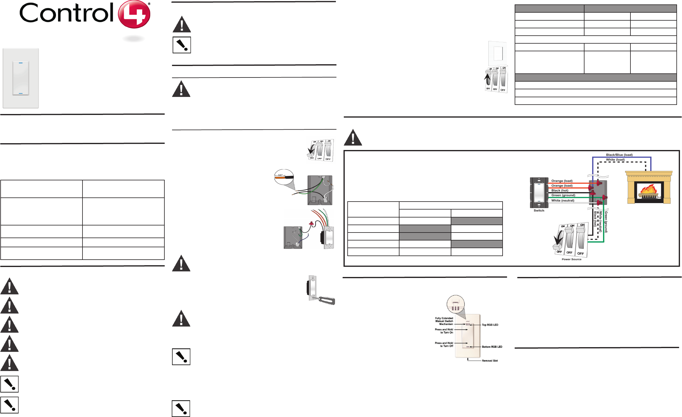
Prepare the wires by removing the pre-cut
insulation from the appropriate Fireplace Switch
leads. Wire insulation should be stripped back
5/8 of an inch from the wire end (as shown).
WARNING! Orange wires are only to be used in low-voltage switching. Do not
connect them to 120V sources or any loads outside the supported types and
ratings.
1.
2.
3.
4. Connect the Fireplace Switch wires to the wall
box wires using wire nuts according to the
relevant wiring diagram.
See “Sample Wiring Confi guration.”
5. Mount fi replace switch into wall box by partially securing the wall
box screws attached to the fi replace switch. Ensure that the word
“Top” on the fi replace switch frame is facing up. Bend wires in a
zigzag pattern so that they easily fold into the wall box.
WARNING! Ground the Wireless Fireplace Switch in accordance with the
National Electric Code (NEC) requirements. Although the fi replace switch’s
aluminum yoke plate and green ground wire are directly bonded together
inside the fi replace switch, DO NOT rely solely upon the yoke plate’s contact
with a metal wall box for adequate grounding. Use the fi replace switch’s
ground wire to make a secure connection to the safety ground of the electrical
system.
IMPORTANT! Not grounding this product according to the preceding may
result in an installation less immune to damage caused by electrical
disturbances, such as lightning, and void the warranty.
6. If you are using the Control4 push-on (screw-less) wall plate that shipped with your
Fireplace Switch:
a. For a single-gang scenario, attach the black plastic sub-plate using the provided
sub-plate screws.
IMPORTANT! Tighten the screws until the back side of the metal yoke plate is
even with the wall surface, but no farther. Over-tightening can damage the fi re-
place switch and cause mechanical malfunction. Do NOT use a power screw
driver to install this device as this may lead to over-tightening.
Sample Wiring Confi guration
Single-Location Scenario—Power Source at Wall Box
NOTE: This device will not function without a neutral AC connection.
To wire the Fireplace Switch for a Control4 single-location scenario in which the
power is fi rst routed to the wallbox, connect together and cap with a wire nut the
wires indicated in the following table:
Fireplace Switch Wires Wires in the Wall Box
From Power Source To Fireplace
White (neutral) White (neutral) None
Orange (load) None White (load)
Orange (load) None Black (load)
Black (hot) Black (hot) None
Green (ground) Green (ground) Green (ground-optional)
WARNING! The following wiring diagram is for demonstration purposes only. Refer to your manufacturer’s electronic module and gas valve
instructions for correct wiring procedures. Improper installation of electronic devices can cause damage to the module, valve or remote receiver.
Operation and Confi guration
On initial power up, the unit will fl ash the
Red/Green/Blue (RGB) LEDs, which can be
programmed with different colors for different
states or color preferences. To set up this
switch for use with a Control4 system, refer to
your system setup documentation.
To operate this switch as a stand-alone device,
refer to the following table.
In case there is a power outage, the Wireless
Fireplace Switch is equiped with a manual
switching mechanism. To close the Fireplace
Switch, pull up on the Manual Switch Mecha-
nism with your fi ngernail.
Operate Fireplace Switch Expected behavior of RGB LEDs:
To operate the Fireplace Switch: Top Bottom
Turn ON: Tap top. Lit, full brightness Not lit
Turn OFF: Tap bottom. Not lit Lit, full brightness
To operate the Fireplace Switch manually during a power outage:
To turn on the Fireplace Switch: Top Bottom
Pull up on the Manual Switch
Mechanism and fully extend
(about 0.5”) to close the switch to
the fi replace.
Not lit Not lit
Care and Cleaning
Do NOT paint the Fireplace Switch or its wall plate.
Do NOT use any chemical cleaners to clean the switch.
Clean surface with a soft damp cloth as needed.
Limited 2-Year Warranty
Control4 Corporation (“Control4”) warrants that at the time of fi rst-consumer sale, this
product will be free from defects in material and manufacture. Control4 further war-
rants that for a period of 2 years (24 months) after initial consumer sale, the product will
function in accordance with its specifi cation, provided that it is installed and maintained
under normal and proper use. This warranty extends only to products purchased directly
from Control4 or an Authorized Control4 Reseller. If the product proves to be defective
in material or workmanship during the warranty period, it may be returned to the place
of purchase and Control4 will, at its sole option, repair or replace the product with a like
product. This warranty provides the consumer purchaser with specifi c legal rights, which
may vary per state or country. For complete warranty information, including details on
consumer legal rights as well as warranty exclusions, visit www.control4.com/warranty.
Regulatory Compliance
FCC
FCC ID: R33C4FS1Z
This device complies with Part 15 of the FCC Rules. Operation is subject to the following
two conditions: (1) this device may not cause harmful interference, and (2) this device
must accept any interference received, including interference that may cause undesired
operation.
This equipment has been tested and found to comply with the limits for a Class B digital
device, pursuant to Part 15 of the FCC Rules. These limits are designed to provide
reasonable protection against harmful interference in a residential installation. This
equipment generates, uses, and can radiate radio frequency energy and, if not installed
and used in accordance with the instructions, may cause harmful interference to radio
communications. However, there is no guarantee that interference will not occur in a
particular installation. If this equipment does cause harmful interference to radio or televi-
sion reception, which can be determined by turning the equipment off and on, the user is
encouraged to try to correct the interference by one or more of the following measures:
• Reorient or relocate the receiving antenna.
• Increase the separation between the equipment and receiver.
• Connect the equipment into an outlet on a circuit different from that to which the
receiver is connected.
• Consult the dealer or an experienced radio/TV technician for help.
IMPORTANT! Any changes or modifi cations not expressly approved by the
party responsible for compliance could void the user’s authority to operate this
equipment.
ETL Statement
ETL Control Number: 3129831
This product has been tested by ETL and was found to comply with the Standard for
Safety for Industrial Control Equipment:
• UL/ANSI Standard 508 (Seventeenth Edition)
• CSA Standard C22.2 No. 14-05
Industry Canada
IC: 7848A-C4FS1Z
This Class B digital apparatus complies with Canada ICES-003.
Cet appareil numérique de la classe B est conforme à la norme NMB-003 du Canada.
About this Document
Protected under U.S. Patents 7,335,845, 7,106,261 and licensed under U.S. Patents
5,905,442 and 5,982,103
United States Patents Pending. ©2009 Control4. All rights reserved. Control4, the
Control4 logo and Everyday Easy are registered trademarks or trademarks of Control4
Corporation in the United States and/or other countries. All other names or brands may
be claimed as property by their respective owners. Pricing and specifi cations subject to
change without notice. Part Number: 200-00048 Rev A 6/10/2009