Snap One C4HC250 HOME AUTOMATION CONTROLLER User Manual USERS MANUAL
Control4 HOME AUTOMATION CONTROLLER USERS MANUAL
Snap One >
USERS MANUAL
™Box Contents
The following items are included in the HC-250 box:
• HC-250 Controller
• AC power cord
• IR emitters (4)
• Universal Television Mounting Plate
• Screws (4)
• Contact/Relay Terminal Block
• Ferrite clamps (4)
Accessories Available for Purchase
• Rack Mount Kit (C4-1URMK1B-B or C4-
1URMK2B-B)
• Serial Cable Kit (C4-CBL3.5MM-DB9B)
Warnings
WARNING! To reduce the risk of electrical
shock, do not expose this apparatus to rain or
moisture.
AVERTISSEMENT! Pour réduire le risque de
choc électrique, n’exposez pas cet appareil à la
pluie ou à l’humidité.
CAUTION: In an over-current condition on
USB or contact output the software disables
the output and then blinks the power LED for
10 seconds. When a USB overcurrent fault is
detected, you will see the power light blink the
LED five (5) times per second. When a contact
overcurrent fault is detected, you will see the
power light blink the LED 12 times a second.
After the 10-second blinking period is over the
over-current circuit will be re-enabled. If the
over-current condition remains, then the same
sequence will repeat itself.
ATTENTION : Dans une condition de
surintensité sur USB ou sortie de contact le
logiciel désactive sortie, puis le DEL Power
clignote pendant 10 secondes. Quand une
erreur de condition de surintensité sur USB
est détectée, vous verrez le DEL Power
clignoté le DEL (5) fois par seconde et puis
quand un défaut de condition de surintensité
sur contact est détecté, vous verrez le DEL
clignoté 12 fois par seconde. Après la période
Supported Model
• C4-HC250-BL – HC-250 Controller, Black
Introduction
The Control4® HC-250 Controller (HC-250) provides
ways to control lights, home theaters, distributed
audio and video systems, and other devices
controlled by Infrared (IR), IP, Serial, Contact, or Relay
connections. The Controller has a fast processor,
built-in WiFi, HDMI for audio and video, improved
ZigBee radio, and is perfect for smaller systems!
The HC-250 also provides extensive media
management for audio and video content: CDs,
DVDs, and Blu-ray Discs, or digital media stored on
connected devices. Use an external storage device
with USB or NAS connectivity to store music and
photos. The HC-250 fits easily behind a TV, stacked
with AV devices, or mounted on a rack using the
Rack Mount Kit (sold separately).
After you install and configure the HC-250 (using the
Composer Pro software) along with other system
components, your customers can control their
system using the On-Screen Navigator, MyHome
apps, System Remote Controls, Touch Screens, or
any other Control4-supported interface devices (sold
separately).
HC-250 Controller
Installation Guide
1
™
de 10 secondes de clignotement, le circuit de
sur-courant sera réactivé. Si la condition de
surintensité reste donc la même, la séquence
se répète.
For more information, refer to the Products or
Documentation pages at www.control4.com.
Requirements and Specifications
NOTES:
(1) We recommend using Ethernet rather than
WiFi for the best network connectivity.
(2) The Ethernet or WiFi network should
be installed prior to starting the HC-250
installation.
(3) The HC-250 is only compatible with PoE
injectors that have DC ground isolated from
AC ground. The easiest way to determine if
this is the case is to use PoE injectors that only
have a two-prong AC power cord. You can find
additional PoE information on the Control4
Knowledgebase.
(4) Ferrite clamp installation. When installing
a Control4® HC-250 Controller, also install the
enclosed ferrite clamps as described in this
document.
Ethernet cable. Install two (2) ferrite clamps
on the Ethernet cable no farther than 6 inches
from the HC-250 Ethernet jack.
Video cable. Install two (2) ferrite clamps on
each end of the HDMI or Component video
cable no farther than 6 inches from the HC-
250 and the TV.
HC-250 Controller
Installation Guide
The software required to configure this device is
Composer Pro. See the Composer Pro User Guide for
details.
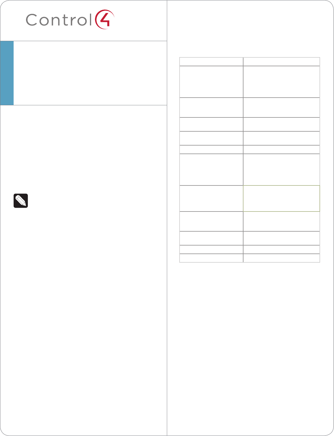
HC-250 Specifications
Model Number C4-HC250-BL
Network Ethernet—required
WiFi (only supported
when the unit is used in a
single-Controller system or as a
Secondary Controller)
Media Recognition Online CD/DVD/Blu-ray
recognition and media information
service
Video HDMI 1.4 output; Component Video
output
Audio Playback Formats MP3: 32kbps to 320kbps, CBR,
VBR, AAC, and FLAC
Display LED indicators
Power Requirements 100-240 VAC, 60/50 Hz, 0.25 A
MAX. Power limits: 30W maximum,
10W minimum. PoE requirement:
13W. IR: <100 mW or 20mA of
current.
Contact (1) DC - 36V maximum operation (low
voltage)
Maximum output current for 12V
rail: 125mA
Relay (1) AC - 36V, 2A
DC - 24V
maximum operation (low voltage)
Dimensions (H x W x D) 1.23” (31.19 mm) x 8.59” (218.13 mm)
x 4.92” (125.01 mm)
Weight 1.3 lbs/0.589 kg
Shipping Weight 2.7 lbs/1.224 kg
Additional Resources
The following resources are available for more
support.
• Control4 Knowledgebase and Forums
• Control4 Technical Support
• Control4 website: http://www.control4.com
• Composer documentation in online help or PDF
format available on the Dealer portal
2
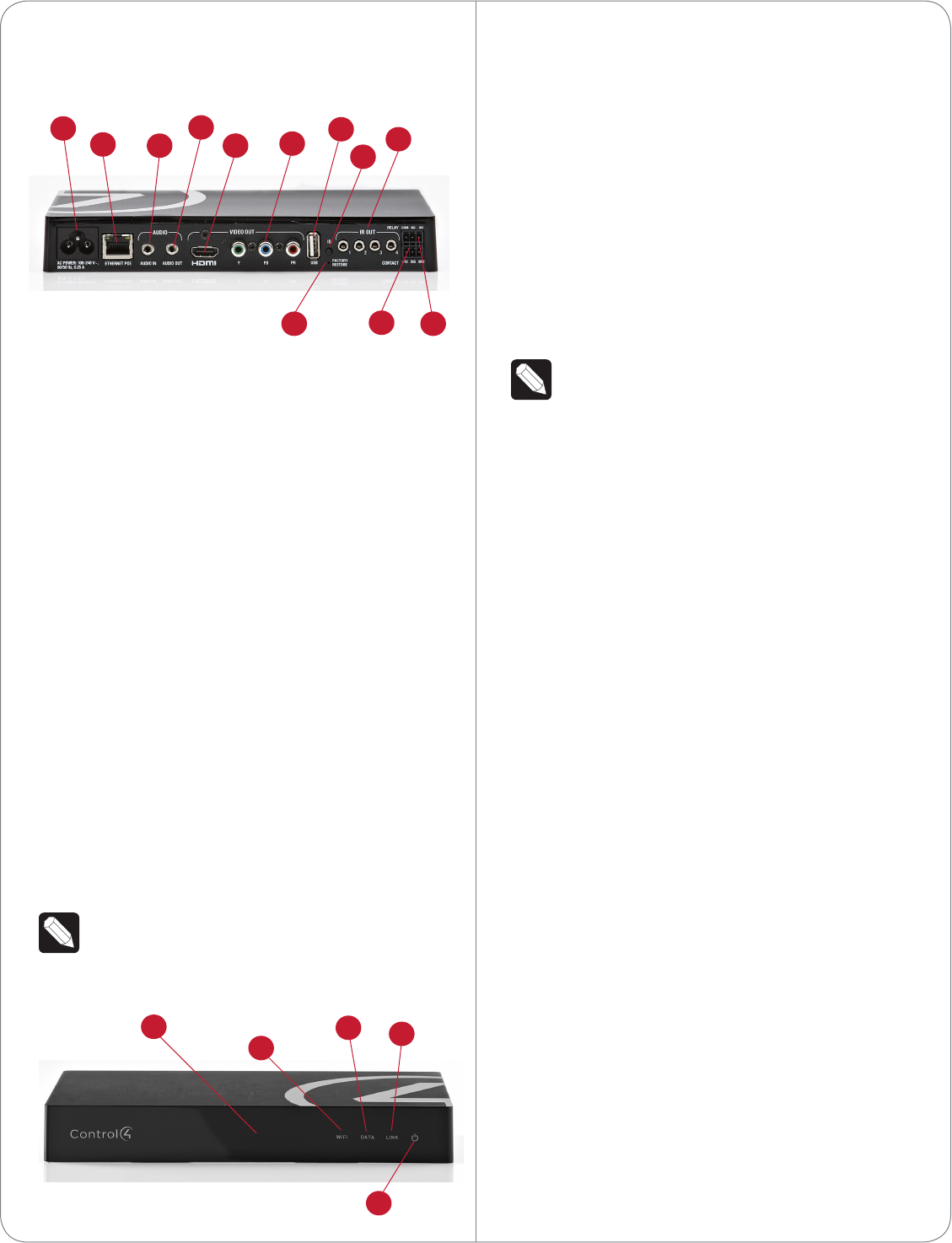
1 Power Plug Port. AC power receptacle for an IEC
320 power cord.
2 Ethernet/PoE. RJ-45 jack for a 10/100 BaseT
Ethernet connection. Supports PoE (802.3af).
3 Audio In (1). 3.5 mm jack for stereo channel input
(line level) for one (1) stereo analog source.
4 Audio Out (1). 3.5 mm jack for stereo channel
line output (line level) for amplifiers or audio
switches.
5 Video Out. An HDMI port to display navigation
menus on a monitor or TV. Also an Audio Out
over HDMI.
6 Video Out. Component port.
NOTE: Use only an HDMI or Component cable
in one of these ports, not both.
7 USB. One (1) port for an external storage device
or a USB drive (e.g., FAT32-formatted devices).
See “Using External Storage Devices” in this
document for more information.
8 Identification Button. Easily-pressed button to
identify the device in Composer Pro.
9 IR and Serial Outs (4). 3.5 mm jacks for up to
four (4) IR emiiters or for a combination of IR
emitters and serial devices. Ports 1 and 2 can
be configured independently for serial control,
e.g., receivers or disc changers, or for IR control.
See “Set Up IR Emitters or IR Blaster” in this
document for more information.
10 Factory Restore Button. Restores the Controller
to its factory defaults. This also reboots the
Controller.
11 Contact (1). Pluggable terminal block connector
for one (1) dry contact closure, logic input
connection, e.g., door contact sensor, or motion
sensor. Provides power for small devices (12V),
signal input (SIG), and return path (GND).
12 Relay. Pluggable terminal block connector for
one (1) Normally Closed or Normally Opened
switchable connection, e.g., a blind, a fireplace, or
a projector screen. The set contains a connection
for Normally Opened (NO), Normally Closed
(NC), and Common (COM).
Installation Instructions
To install the Controller:
1 Ensure that the home network is in place before
starting system setup. The HC-250 requires a
Front View
Figure 1. Front View
1 WiFi LED. This LED blinks first Red, then Orange,
and finally Blue during the boot process. When
the operating system is running, the WiFi driver
changes the LED color depending on the signal
strength of its connection to its associated
access point. Color/signal strength indicators:
Orange=Fair to Good, Blue=Excellent, and No
Light=No connection.
2 Data LED. The Blue LED indicates that the
Controller is streaming audio.
3 Link LED. The Blue LED indicates that the
Controller has been identified in a Control4
Composer project and is communicating with
Director.
4 Power LED. The Blue LED indicates that AC or
PoE power is present. The Controller turns on
immediately after power is applied to it.
5 IR Window/IR Blaster. For capturing third-party
IR codes from hand-held devices (for example,
remote controls) or blasting IR codes.
Back View
NOTE: Audio cables are not provided with this
product.
Figure 2. Back View
3
4567
89
10 11 12
123
1
23
4
5
network connection (Ethernet - preferred or
WiFi) to use all of the features as designed. When
connected, the Controller can access web-based
media databases, communicate with other IP
devices in the home, and access Control4 system
updates.
2 Mount options. The HC-250 can be mounted or
placed behind a TV, mounted on a wall, placed
in a rack, or stacked on a shelf. See “Wall Mount
Options” below if mounting the HC-250 on a wall.
3 Connect the HC-250 to the network.
• Ethernet. To connect using an Ethernet
connection, plug the data cable from the home
network connection into the Controller’s RJ-45
port (labeled “Ethernet”) and the network port
on the wall or at the network switch.
• WiFi. To connect using WiFi, first connect the
unit to Ethernet, and then use Composer Pro’s
System Manager to reconfigure the unit for WiFi.
You can find sample instructions in the Composer
Pro User Guide, “Configuring Speaker Point for
WiFi.”
4 Power up the Controller. Plug the power cord
into the Controller’s power plug port and then
into an electrical outlet. If you are powering the
Controller using PoE, you can skip this step.
5 Connect system devices. Attach the devices as
described in “Connect the Devices.”
6 Set up any external storage devices as described
in “Setting Up External Storage Devices” in this
document.
Wall Mount Options
• Mount the HC-250 horizontally using one (1)
standard single-gang back box (sold separately).
The wall mounting plate has four (4) horizontal
sets of slots. Install a single-gang back box
allowing the screws to protrude .08” from the
wall.
• Mount the HC-250 horizontally or vertically using
one (1) standard double-gang back box (sold
separately). Install a standard double-gang back
box allowing the screws to protrude .08” from
the wall.
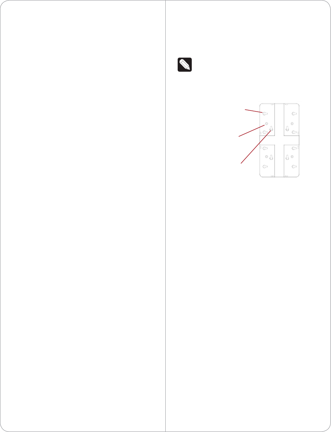
• Mount the HC-250 horizontally or vertically (see
Figure 3) using four (4) screws (not provided)
placed directly into a wall stud or studs. Using
the mounting plate as a template, screw the four
(4) screws into a stud to align with the four (4)
center slots for vertical positioning or into two
(2) studs to align with the four (4) corner slots
for horizontal positioning and allowing the screws
to protrude .08” from the wall.
NOTE: To check the fit of the screws, place the
wall mounting plate over the screws before
attaching it to the bottom of the Controller.
Figure 3. Screw Location
Mount the HC-250
1 Use the four (4) screws (provided) to attach the
mounting plate to the bottom of the Controller.
Ensure that the narrow end of the slots is on top
when the device is installed.
2 Arrange the wires to fit in the wire channels on
the mounting plate.
3 Line up the slots on the mounting plate with the
screws.
4 Press the device onto the screws and slide it
down until the screws are in the narrow end of
the slots.
5 Connect all applicable devices to the HC-250
using the connection options described next.
Connect the IR Ports/Serial Ports
(Optional)
The HC-250 provides four (4) IR ports; Ports 1 and
2 can be reconfigured independently for serial
communication. If not used for serial, they can be
used for IR. Connect a device to the HC-250, for
example, a receiver or disc changer, using the special
serial cable (optional). Serial ports support many
dierent baud rates (acceptable range: 1200 to
115200 baud for odd and even parity).
4
Slots for mounting
Controller horizontally
Holes for attaching
plate to Controller
Slots for mounting
Controller vertically
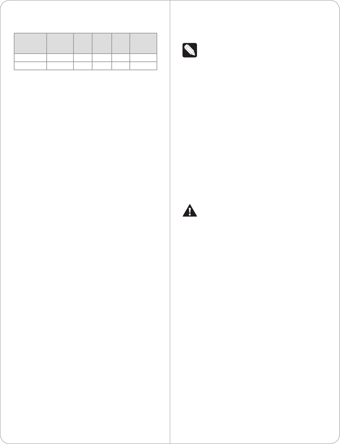
The following table shows the serial communication
values.
Hardware
Flow
Control
Odd
Parity
Even
Parity
No
Parity
Other
Serial Port 1 X X X
Serial Port 2 X X X
To configure a port for serial or IR, make the appro-
priate connections in your project using Composer
Pro. See the Composer Pro User Guide for details.
Set Up IR Emitters or IR Blaster
Your system may contain third-party products
that are controlled through IR commands (usually
using remote controls). To provide a way for the
Controller to control a device that only recognizes IR
commands, complete one of the following setups:
• IR Emitters
• IR Blaster
IR Emitters
1 Plug the 3.5 mm connector end of one of the four
(4) IR stick-on emitters provided into an IR Out
port on the HC-250.
2 Place the stick-on emitter end over the IR
receiver on the Media Player, TV, or other target
device to drive IR signals from the HC-250 to the
target.
IR Blaster
The HC-250 is also equipped with an IR blaster
which is located just left of the front LEDs. To use the
blaster rather than an IR emitter:
1 In Composer, connect the IR Blaster of the
Controller to the IR In for the device you want to
control.
2 Test and verify that the HC-250 is positioned in
such a way that the blaster can reach the device
you want to control.
Setting Up External Storage Devices
You can store and access media from an external
storage device, for example, a network hard drive
or USB memory device, by plugging the USB drive
into the USB port and configure or scan the media in
Composer Pro.
NOTES:
(1) We support only USB drives that are
externally powered or USB sticks (solid state).
Self-powered USB drives are not supported.
(2) When using USB storage devices on an
HC-250, you can only use one (1) partition with
a 2TB maximum size. This limitation applies to
the USB storage on all other Controllers also.
Composer Pro Driver Information
Select the Home Controller HC-250 driver in
Composer Pro and add it to your Composer project.
See the Composer Pro User Guide for details.
Troubleshooting
Factory Restore Button
CAUTION! This action deletes the Composer
project.
To restore the HC-250 for system recovery to the
factory default image, perform the following steps:
1 Disconnect power to the HC-250.
2 Insert one end of a paper clip into the small
hole on the back of the HC-250 that is labeled
‘Factory Restore.’
3 While pressing and holding the Factory Restore
button, power on the HC-250.
4 Hold the button until the WiFi Status LED blinks
Orange. This should take 5 to 7 seconds. The
Status LED will blink Orange while the restore
process is running.
Identification Button (Network Reset)
To reset the HC-250 network settings to the default,
perform the following steps:
1 Disconnect power to the HC-250.
2 While pressing and holding the ID button on the
back of the HC-250, power on the HC-250.
3 Hold the ID button until the Data, Link and Power
LEDs are solid Blue, then immediately release the
5

©2012 Control4. All rights reserved. Control4, the Control4 logo, the Control4 iQ logo and the Control4 certified logo are registered trademarks or trademarks of Control4 Corporation in
the United States and/or other countries. All other names and brands may be claimed as the property of their respective owners.
control4.com |
™
button.
4 If during the boot sequence the Status LED stays
Orange, press and hold the Identification button
until the LED blinks Blue, and then release it.
Regulatory/Safety Information
To review regulatory information for your particular
Control4 products, see the information located on
the Control4 website at: http://www.control4.com/
regulatory/.
Warranty
Go to http://www.control4.com/warranty for details.
About This Document
Part number: 200-00240, Rev. C 05/03/2012
6

Regulatory Compliance & Safety Information for Contol4 Model C4-HC250-BL.
Electrical Safety Advisory
Important Safety Information
Read the safety instructions before using this product.
1. Read these instructions.
2. Keep these instructions.
3. Heed all warnings.
4. Follow all instructions.
5. Do not use this apparatus near water.
6. Clean only with dry cloth.
7. Do not block any ventilation openings. Install in accordance with the manufacturer’s
instructions.
8. Do not install near any heat sources such as radiators, heat registers, stoves, or other
apparatus (including amplifiers) that produce heat.
9. Do not defeat the safety purpose of the polarized or grounding-type plug. A polarized
plug has two blades with one wider than the other. A grounding type plug has two blades
and a third grounding prong. The wide blade or the third prong is provided for your safety.
If the provided plug does not fit into your outlet, consult an electrician for replacement of
the obsolete outlet.
10. Protect the power cord from being walked on or pinched particularly at plugs,
convenience receptacles, and the point where they exit from the apparatus.
11. Only use attachments/accessories specified by the manufacturer.
12. Use only with the cart, stand, tripod, bracket, or table specified by the manufacturer, or
sold with the apparatus. When a cart is used, use caution when moving the
cart/apparatus combination to avoid injury from tip-over.
13. Unplug this apparatus during lightning storms or when unused for long periods of time.
This equipment uses AC power which can be subjected to electrical surges, typically
lightning transients which are very destructive to customer terminal equipment connected
to AC power sources. The warranty for this equipment does not cover damage caused
by electrical surge or lightning transients. To reduce the risk of this equipment becoming
damaged it is suggested that the customer consider installing a surge arrestor.
14. Refer all servicing to qualified service personnel. Servicing is required when the
apparatus has been damaged in any way, such as power-supply cord or plug is
damaged, liquid has been spilled or objects have fallen into the apparatus, the apparatus
has been exposed to rain or moisture, does not operate normally, or has been dropped.
15. Use the mains plug to disconnect the apparatus from the AC mains. The mains plug shall
remain readily operable.
16. To completely disconnect unit power from the AC mains, disconnect the unit’s power cord
from the mains socket. To reconnect power, plug the unit’s power cord into the mains
socket following all safety instructions and guidelines.
17. CAUTION: As with all batteries, there is a risk of explosion or personal injury if the
battery is replaced by an incorrect type. Dispose of used battery according to the
instructions of the battery manufacturer and applicable environmental guidelines. Do not
open, puncture or incinerate the battery, or expose it to conducting materials, moisture,
liquid, fire or heat above 54° C or 130° F.
18. Never push objects of any kind into this product through cabinet slots as they may touch
dangerous voltage points or short out parts that could result in fire or electric shock.
19. This product can interfere with electrical equipment such as tape recorders, TV sets,
radios, computers and microwave ovens if placed in close proximity.
The lightning flash and arrow head within the triangle is a warning sign alerting
you of dangerous voltage inside the product
Caution: To reduce the risk of electric shock, do not remove cover (or back). No
user serviceable parts inside. Refer servicing to qualified service personnel.
The exclamation point within the triangle is a warning sign alerting you of
important instructions accompanying the product.
See marking on bottom / back of product
Warning!: To reduce the risk of electrical shock, do not expose this
apparatus to rain or moisture
AVERTISSEMENT! Pour réduire le risque de choc électrique,
n'exposez pas cet appareil à la pluie ou à l'humidité.
WARNUNG! Um das Risiko des elektrischen Schlages zu verringern,
setzen Sie diesen Apparat nicht Regen oder Feuchtigkeit aus.
Save these instructions
Compliance of this equipment is confirmed by the following label that is placed on the equipment:
USA & Canada Compliance
FCC Part 15, Subpart B / ICES-003Unintentional Emissions Interference Statement
This equipment has been tested and found to comply with the limits for a Class B digital device,
pursuant to Part 15 of the FCC rules and Industry Canada ICES-003. These limits are designed
to provide reasonable protection against harmful interference when the equipment is operated in
a residential installation. This equipment generates uses and can radiate radio frequency energy
and, if not installed and used in accordance with the instructions, may cause harmful interference
to radio communications. However, there is no guarantee that interference will not occur in a
particular installation. If this equipment does cause harmful interference to radio or television
reception, which can be determined by turning the equipment off and on, the user is encouraged
to try to correct the interference by one or more of the following measures:

Reorient or relocate the receiving antenna.
Increase the separation between the equipment and receiver.
Connect the equipment into an outlet on a circuit different from that to which the receiver
is connected.
Consult the dealer or an experienced radio/TV technician for help.
This device complies with part 15 of the FCC rules and Industry Canada ICES-003. Operation is
subject to the following two conditions: (1) This device may not cause harmful interference, and
(2) this device must accept any interference received, including interference that may cause
undesired operation.
Le présent appareil est conforme aux CNR d’Industrie Canada applicables aux appareils radio
exempts de licence. L’exploitation est autorisée aux deux conditions suivantes : (1) l’appareil ne
doit pas produire de brouillage, et (2) l’utilisateur de l’appareil doit accepter tout brouillage
radioélectrique subi, même si le brouillage est susceptible d’en compromettre le fonctionnement.
IMPORTANT! Any changes or modifications not expressly approved by the party responsible for
compliance could void the user’s authority to operate this equipment.
IMPORTANT! Tous les changements ou modifications pas expressément approuvés par la partie
responsable de la conformité ont pu vider l’autorité de l’utilisateur pour actionner cet équipement.
Ferrite clamp installation. When installing a Control4® HC-250 Controller, also install the four (4)
enclosed ferrite clamps as described in this document.
Ethernet cable. Install two (2) ferrite clamps on the Ethernet cable no farther than 6 inches from
the HC-250 Ethernet jack.
Video cable. Install two (2) ferrite clamps on each end of the HDMI or Component video cable no
farther than 6 inches from the HC- 250 and the TV.
Compliance of this equipment is confirmed by the following label that is placed on the equipment:
FCC Part 15, Subpart C / RSS-210 Intentional Emissions Interference Statement
Compliance of this equipment is confirmed by the following certification numbers that are placed
on the equipment:
Notice: The term “FCC ID:” and “IC” before the certification number signifies that FCC and
Industry Canada technical specifications were met.
FCC ID: R33C4HC250
IC: 7848A-C4HC250
This equipment must be installed by qualified professionals or contractors in accordance with
FCC Part 15.203 & IC RSS-210, Antenna Requirements. Do not use any antenna other than the
one provided with the unit.

RF Radiation Exposure Statement
This equipment complies with the FCC/IC radiation exposure limits set fourth for portable
transmitting devices operation in an uncontrolled environment. End users must follow the specific
operating instructions to satisfy RF exposure compliance.
The equipment should only be used or installed at locations where there is normally at
least a 20cm separation between the antenna and all persons.
This transmitter must not be co-located or operation in conjunction with any other
antenna or transmitter.
Any changes or modifications not expressly approved by the party responsible for
compliance could void the user’s authority to operate this equipment.
European Compliance
Conformity of the equipment with the guidelines below is attested by the application of the CE
mark.
CE Declaration of Conformity
Manufacturer’s Name: CONTROL4 CORPORATION
Manufacturer’s Address: 11734 S. ELECTION ROAD SUITE 200
SALT LAKE CITY
UT 84020 USA
EU Representative Name: CONTROL4 EMEA LIMITED
EU Representative Address: UNIT3, GREEN PARK BUSINESS CENTRE
SULTON-ON-THE FOREST
YORK YO61 IET, UNITED KINGDOM
Product Name(s): Home Controller
Brand: Contol4
Model(s): C4-HC250-BL
Product Standard(s) to which Conformity of the Council Directive(s) is declared:
EMC - 2004/108/EC “Electromagnetic Compatibility (EMC) Directive”:
(Emissions) EN 55022:2006, (Immunity) EN 55024:1998, EN 301 489-1:2008, EN 301 489-
17:2009, EN 61000-3-2:2004 & EN 61000-3-3:2002
Safety – 206/95/EC “Low Voltage Directive (LVD)”:
EN 60950-1:2006 (2nd Edition) .
Telecom & Radio - 1999/5/EC Radio equipment and Telecommunications Terminal
Equipment (R&TTE) Directive:
EN 300 328 V1.7.1 (2006-10)
RoHS - 2002/95/EC Restriction of the Use of certain Hazardous Substances in Electrical
and Electronic Equipment (EEE) & WEEE - 2002/96/EC Waste of Electrical and Electronic
Equipment (EEE).
We, the undersigned, hereby declare that the equipment specified above conforms to the above
directives and standards. Date of Issue: May 9, 2012
Legal Representative
Signature
Roger Midgley
Sr. Regulatory Compliance Engineer
National Restrictions
This product may be used in all EU countries (and other countries following the EU directive
1999/5/EC) without any limitation except for the countries mentioned below:
Ce produit peut être utilisé dans tous les pays de l'UE (et dans tous les pays ayant transposés la
directive 1999/5/CE) sans aucune limitation, excepté pour les pays mentionnés ci-dessous:
Questo prodotto è utilizzabile in tutte i paesi EU (ed in tutti gli altri paesi che seguono le direttive
EU 1999/5/EC) senza nessuna limitazione, eccetto per i paesii menzionati di seguito:
Das Produkt kann in allen EU Staaten ohne Einschränkungen eingesetzt werden (sowie in
anderen Staaten die der EU Direktive 1999/5/CE folgen) mit Außnahme der folgenden
aufgeführten Staaten:
France
In case the product is used outdoors, the output power is restricted in some parts of the band.
See Table 1 below or check http://www.arcep.fr/ for more details.
Dans la cas d'une utilisation en extérieur, la puissance de sortie est limitée pour certaines parties
de la bande. Voir la table ci-dessous ou visitez http://www.arcep.fr/ pour de plus amples details
Table 1 Applicable Power Levels in France
Location Frequency Range (MHz) Power (EIRP)
Indoor (No restrictions) 2400-2483.5 100 mW (20 dBm)
Outdoor 2400-2454
2454-2483.5
100 mW (20 dBm)
10 mW (10 dBm)
Recycling
Control4 understands that a commitment to the environment is essential for a health life and
sustainable growth for future generations. We are committed to supporting the environmental
standards, laws, and directives that have been put in place by various communities and countries
that deal with concerns for the environment. This commitment is represented by combining
technological innovation with sound environmental business decisions.
WEEE Compliance
Control4 is committed to meeting all requirements of the Waste Electrical and Electronic
Equipment (WEEE) directive (2002/96/EC). The WEEE directive requires the manufacturers of
electrical and electronic equipment who sell in EU countries: (1) label their equipment to notify
customers that it needs to be recycled, and (2) provide a way for their products to be
appropriately disposed of or recycled at the end of their product lifespan. For collection or
recycling of Control4 products, please contact your local Control4 representative or dealer.
Australia / New Zealand Compliance
Compliance of this equipment is confirmed by the following label that is placed on the equipment:
About this Document
Copyright © 2012 Control4 Corporation. All rights reserved. Control4 and the Control4 logo are
registered trademarks or trademarks of Control4 Corporation in the United States and/or other countries.
Part Number 200-00290 Rev A, 5/9/2012