Snap One C4HC3001 Home Controller HC300 User Manual HomeControllerHC300
Control4 Home Controller HC300 HomeControllerHC300
Snap One >
Exhibit 8
Home Controller HC300
Installation Guide
Supported Model
C4-HC300-E-B Home Controller HC300
Graphical Symbols in this Guide
The following symbols and their descriptions draw your attention to important
safe practices and additional information that can help you avoid death, injury,
or loss of material or time.
WARNING! This indicates a potentially hazardous situation that, if not
avoided, may result in death or serious injury. DO NOT IGNORE A
WARNING!
IMPORTANT! This indicates information that will help you avoid
damage to your equipment, loss of materials, or loss of time. PAY
ATTENTION TO THESE IMPORTANT STATEMENTS!
NOTE: This indicates information related to the current topic.
Important Safety Instructions
1. Read these instructions.
2. Keep these instructions.
3. Heed all warnings.
4. Follow all instructions.
5. Do not use this apparatus near water.
6. Clean only with dry cloth.
7. Install in accordance with the manufacturer’s instructions.
8. Do not install near any heat sources such as radiators, heat registers,
stoves, or other apparatus (including amplifiers) that produce heat.
9. Do not defeat the safety purpose of the polarized or grounding-type plug. A
polarized plug has two blades with one wider than the other. A grounding
type plug has two blades and a third grounding prong. The wide blade or the
third prong are provided for your safety. If the provided plug does not fit into
your outlet, consult an electrician for replacement of the obsolete outlet.
10.Protect the power cord from being walked on or pinched particularly at
plugs, convenience receptacles, and the point where they exit from the
apparatus.
11.Only use attachments/accessories specified by the manufacturer.
12.Unplug this apparatus during lighting storms or when unused for long peri-
ods of time.
13.Refer all servicing to qualified service personnel. Servicing is required when
the apparatus has been damaged in any way, such as power-supply cord or
plug is damaged, liquid has been spilled or objects have fallen into the
apparatus, the apparatus has been exposed to rain or moisture, does not
operate normally, or has been dropped.
14.This apparatus has no AC mains power switch. The power cable is the AC
mains disconnect device.
WARNING! To reduce the risk of electrical shock, do not expose this
apparatus to rain or moisture.
WARNING! This CLASS I apparatus must be connected to an AC
mains socket outlet that has a protective earthing connection (i.e., third-
prong ground conductor). DO NOT DEFEAT THE PROTECTIVE
EARTHING CONNECTION!
Introduction to Home Controller HC300
The Control4 Home Controller HC300 provides options for controlling lights,
home theaters, distributed audio systems, and other devices controlled using
various protocols, such as Infra Red (IR), Serial, Contact, and Relay.
It provides extensive media management services for audio sources, such as
CDs and DVDs stored in connected devices. It also allows you to use an
external storage device with USB support for media storage. It also includes
multi-zone audio capabilities, sending music to rooms throughout the home.
Once the controller and other system components are installed and configured
(using Control4 Composer software or another Control4 setup program), your
users can control the system using one of the two user interfaces included with
this controller: On-screen Navigator or System Remote Control.
Control4 Supported Devices
Control4 devices that can be controlled by this controller include:
For a complete list of Control4 supported devices and solutions, see “Products”
at http://www.control4.com.
Requirements and Specifications
Prior to installing this product, ensure that:
• Wired Ethernet network is in place
• A monitor or TV is available for on-screen navigation and control
The Home Controller HC300 specifications are:
What’s in the Box
The following are included in your Home Controller box:
• Home Controller HC300
• Pluggable terminal block connector (1)
• System Remote Control with LCD Navigator display and 4 AAA batteries
• Composite video cable
• IEC power cord
• IR emitters (6)
•Home Controller HC300 Installation Guide (this document)
•Control4 System User Guide
• Control4 System Remote Control User Guide
• Ferrite Cable Clamp (See “Connect to the Contact Port”)
Additional Resources
The following resources are available to provide you with additional support.
• Your authorized Control4 reseller
• Control4 Web Site: http://www.control4.com
• Composer online help
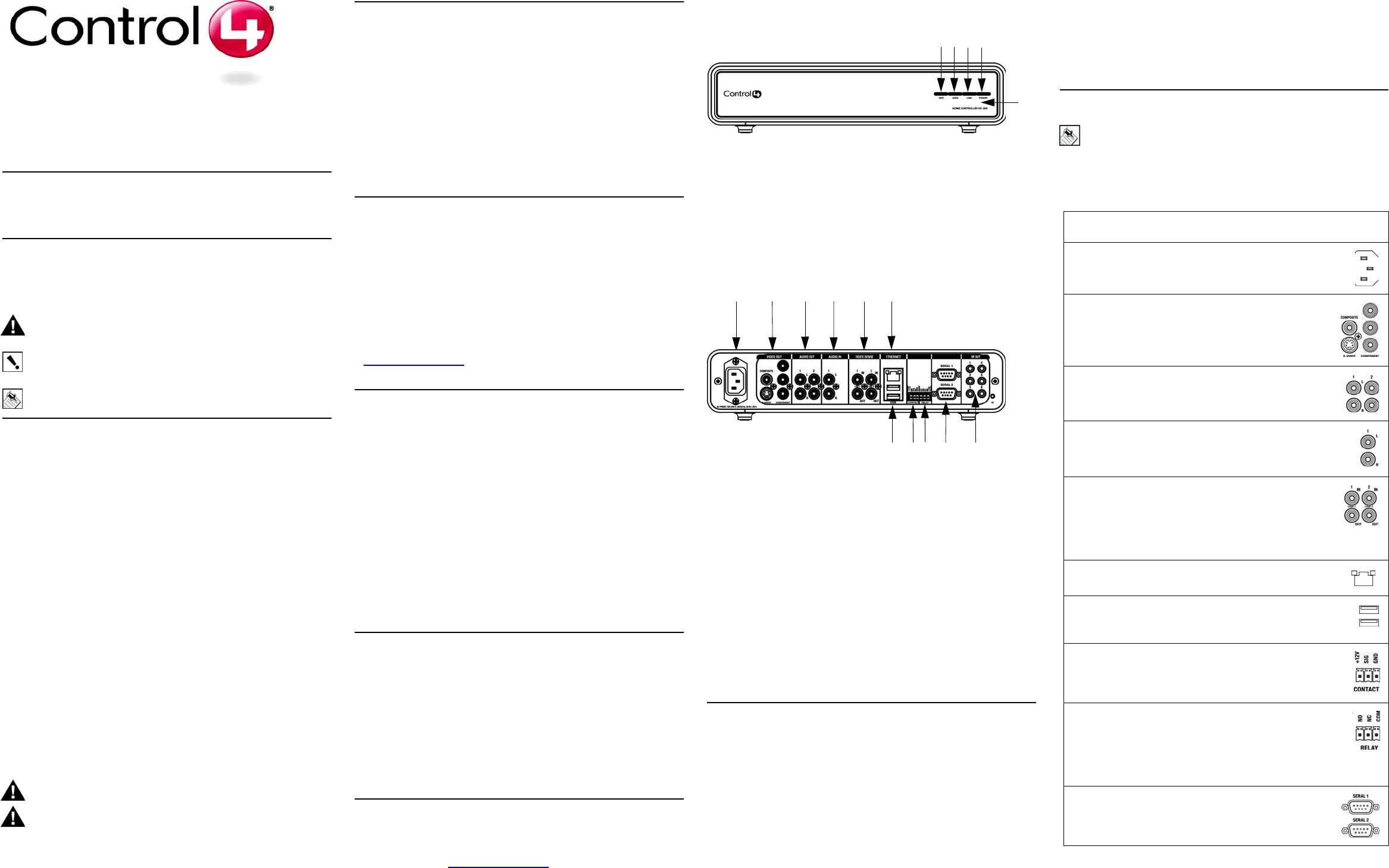
Front View
1. WiFi LED—Indicates Wifi signal strength (red: poor, orange: good,
and green: excellent). These LEDs blink when HC300 is booting.
2. Data LED—Green LED light indicates data is received.
3. Link LED—Green LED light indicates Home Controller has been
identified in a Control4 Composer project.
4. Power LED—Green LED light indicates AC power is present: Turns on
immediately after the power is applied to the device.
5. IR window / IR Blaster—For capturing third-party IR codes from hand-
held devices (such as remote controls) or blasting IR codes.
Back View
1. Power plug port—AC power receptacle for an IEC 320 power cord.
2. Video Out—Composite RCA, S-VIDEO mini-DIN, or Component RCA
jacks.
3. Audio Out (2 Left-Right pairs)—RCA jacks for stereo channel line output
(line level) for amplifiers or audio switches.
4. Audio In (1 Left-Right pair)—RCA jacks for stereo channel input (line
level) for 1 stereo analog source.
5. Video Sense In-Out (2 pairs)—Composite In-Out RCA jack pairs for moni-
toring the On/Off status of up to 2 video sources.
6. Ethernet—RJ-45 jack for a 10/100 BaseT Ethernet connection.
7. USB (2 ports)—For external storage device with USB support (such as
FAT32 formatted devices).
8. Contact (1 set)—Pluggable terminal block connector for 1 dry contact clo-
sure, logic input connection, door contact sensor, or motion sensor.
9. Relay (1 set)—Pluggable terminal block connector for 1 normally closed or
normally opened switchable connection.
10.Serial (2 sets, DB9)—2 serial devices, such as a monitors or TVs.
11.IR Out (6)—3.5 mm jacks for up to 6 IR output transmitters.
Install the System
To install this controller:
1. Ensure that your home network is in place before starting your system
setup: The Home Controller HC300 requires an Ethernet connection in
order to use all features as designed. When connected, the Home Control-
ler can access Web-based media databases and can easily access
Control4 system updates.
2. Connect the controller to the network: If you are using an Ethernet con-
nection for the Home Controller, plug the data cable from the home network
connection into the Home Controller RJ-45 port (labeled “Ethernet”) and the
network port on the wall or at the network switch.
3. Power up the controller: Plug the Home Controller power cord (provided)
into the Home Controller power plug port and an electrical outlet.
4. Connect system devices as described in the “Connect Devices” section
that follows.
5. Set up external storage devices as described in “Set up External Storage
Device” on page 2.
Connect Devices
NOTE: You can use the Interviewer feature in the Composer software
to step you through the connection process or you can set up the
physical connections and then run Interviewer to tell the Control4
system the applicable connections.
Connect all applicable devices to the Home Controller HC300 using one of the
connection options described in the following table.
Table 1. Connection Options
Touch Screen (Wireless or Wall-Mounted)
Mini Touch Screen
Wireless LCD Keypad
Wireless 2, 3, & 6 Button Keypads
Wireless Thermostat
Speaker Point™
Wireless Dimmer
Wireless Switch
Wireless Outlet Dimmer
Wireless Outlet Switch
Multi Channel Amplifier
Audio Matrix Switch
Model Number • C4-HC300-E-B
Media Recognition • AMG online CD/DVD recognition and
media information service
Audio Recording For-
mats • MP3: 192kbps
Audio Playback For-
mats • Uncompressed WAV and PCM: 44.1kHz,
16 bit stereo
• MP3: 32kbps to 320kbps, CBR and VBR
Display • LED indicators
Power Requirements • 100-240 VAC, 60/50 Hz, 0.18 A MAX
Dimensions • H x W x D: 2.78” x 7.24” x 11.98” (with feet
and connectors)
Weight • 4.7 pounds
5
1 2 3 4
7 8 9 10 11
1 2 3 4 5 6
Connection Options
Power plug port—For C6 power connector. See “Power Up the
Home Controller” for more information.
Video Out Options—Composite, Component, or S-Video
port for displaying navigation menus on a monitor or TV. The
Component jack is for displaying high definition video. When
available, use S-Video instead of Composite for a higher qual-
ity display.
Audio Out (2 Left-Right pairs)—RCA jacks for stereo channel
line output (line level) for amplifiers or audio switches.
Audio In (1 Left-Right pair)—RCA jacks for stereo channel input
(line level) for 1 stereo analog source.
Video Sense In-Out (2 pairs)—Composite In-Out port pairs
for monitoring up to 2 video In sources, such as DVD players
or VCRs, that allow the system to determine the On/Off status
of devices. Each Out port allows the signal to loop through the
Home Controller and continue to its intended video connection.
See “Set up External Storage Device” for more information.
Ethernet—RJ-45 for a 10/100 BaseT Ethernet connection. See
“Connect to the Network” for more information.
USB (2 ports)—For external storage device with USB support
(such as FAT32 formatted devices). See “Set up External Storage
Device” for more information.
Contact (1 set)—Pluggable terminal block connector for 1 dry
contact closure, logic input connection, door contact sensor, or
motion sensor. See “Connect to the Contact Port” for more infor-
mation.
Relay (1 set)—Pluggable terminal block connector for 1 nor-
mally closed or normally opened switchable connection, such as
a blind, a fireplace, or a projector screen. The set contains a con-
nection for Common (COM) and Normally Closed (NC) or Nor-
mally Opened (NO). See “Connect to the Relay Port” for more
information.
Serial (2 sets)—DB9 connector for a serial device, such as a
monitor or DVD changer. See “Connect the Serial Ports” for
more information.
Use the remaining content in this section to learn more about some of these
connection options.
Use Video Sense Loops
Video sensing can enhance the ability to sense the power state of a device,
such as whether the device is “on” or “off.” If you need to add video signal
sensing capabilities for a video device (such as a TV, VCR, DVD player, etc.),
connect one of the device’s composite Video Out ports to a Home Controller
Video Sense In port. Then, use the companion Video Sense Out port (where
available) for the device’s video out as needed.
For Video Sense only (no loop-through), connect a device’s Composite Video
Out port to one of the two Video Sense In ports.
Use Pluggable Terminal Block Connectors
For the Contact and Relay ports, the Home Controller makes use of a
pluggable terminal block connector—a removable plastic part to lock in
individual wires. This connector is included.
To connect a device to the Pluggable Terminal Block:
1. Insert one of the wires required for your device into the appropriate opening
in the Pluggable Terminal Block you reserved for that device (refer to
Table 1 on page 2).
For example, if you were adding a motion sensor, you would connect its wires to the
following Contact openings: power input to +12V output signal to SIG, and ground
connector to GND. See the sections that follow for instruction on connecting the
various protocols.
2. Lower the openings latch until it locks the wire in place.
3. Repeat Steps 1-2 for all wires required for your device.
NOTE: When you connect dry contact closure devices, such as door
switches, connect the switch between +12V (Power) and SIG (Signal).
Connect to the Contact Port
The Home Controller provides one contact port as a subset of the pluggable
terminal block provided. See the following figures to determine how to connect
the device to a contact port.
NOTE: Before using a device in the contact port, attach the ferrite
(supplied) to the cable.
Figure 1: Contact Port for Voltage Source (i.e. Motion Sensor)
Figure 2: Contact for Dry Contact (i.e. Door Contact Sensor.
Figure 3: Connect Contact for Self Powered Voltage Source Device
Connect to the Relay Port
The Home Controller provides one relay port as a subset of the pluggable
terminal block provided.
For most applications, you attach one wire to the common terminal and the
other to the normally open terminal.
The relay switches closed when the relay is activated.
The Home Controller can support applications that require a normally closed
contact.
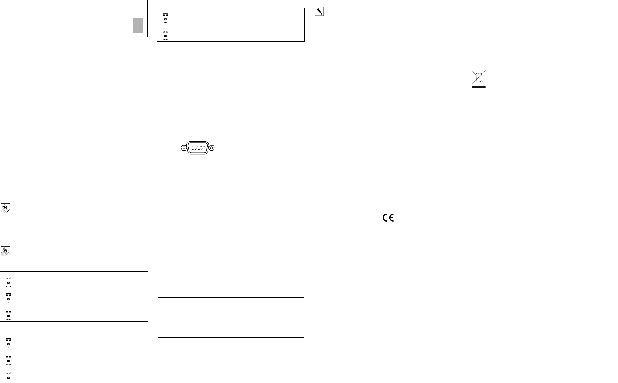
Connect the Serial Ports
The Home Controller provides two DB9-style serial ports. Connect a device to
the Home Controller, like a monitor or TV, by aligning the pins and tightening
the screws.
Figure 4: Connect to DB9 Serial Port
Set Up IR Emitters or IR Blaster
Your system may contain third-party products that are controlled with IR
commands (usually through remote controls). To provide a way for the Home
Controller to control a device that only recognizes IR commands, complete one
of the following setups: IR Emitters or IR Blaster.
IR Emitters
1. Plug the 3.5 mm connector end of one of the 6 IR stick-on emitters provided
into an IR Out port on the Home Controller.
2. Place the stick-on emitter end over the IR receiver on the media player, TV,
or other target device to transmit IR signals from the Home Controller to the
target.
IR Blaster
In addition to IR emitters, the Home Controller is also equipped with an IR
blaster, which is located just under the front LEDs. To use the blaster instead of
an IR emitter:
1. In Composer, connect IR Out #6 of the Home Controller to the IR In of the
device you wish to control.
2. Do not physically connect anything to IR Out Port #6.
3. Test and verify that the Home Controller is positioned in such a way that the
blaster can reach the device you wish to control.
Set up External Storage Device
You can store and access media from an external storage device, such as a
network hard drive or USB memory device. Simply plug the USB drive into one
of the USB ports and configure or scan the media from Composer.
Regulatory Compliance
North America
This product complies with standards established by the following regulatory
bodies:
• Federal Communications Commission (FCC)
• Industry Canada
• Underwriters Laboratories Inc. (UL)
IMPORTANT! Any changes or modifications not expressly approved by
the party responsible for compliance could void the user’s authority to
operate this equipment.
Federal Communications Commission (FCC)
FCC ID: R33C4HC3001
This device complies with Part 15 of the FCC Rules. Operation is subject to the
following two conditions: (1) This device may not cause harmful interference,
and (2) this device must accept any interference received, including
interference that may cause undesired operation.
This equipment has been tested and found to comply with the limits for a Class
B digital device, pursuant to Part 15 of the FCC Rules. These limits are
designed to provide reasonable protection against harmful interference in a
residential installation. This equipment generates, uses, and can radiate radio
frequency energy and, if not installed and used in accordance with the
instructions, may cause harmful interference to radio communications.
However, there is no guarantee that interference will not occur in a particular
installation. If this equipment does cause harmful interference to radio or
television reception, which can be determined by turning the equipment off and
on, the user is encouraged to try to correct the interference by one of the
following measures:
• Reorient or relocate the receiving antenna.
• Increase the separation between the equipment and receiver.
• Connect the equipment into an outlet on a circuit different from that to which
the receiver is connected.
• Consult the dealer or an experienced radio/TV technician for help.
Industry Canada
This Class B digital apparatus complies with Canada ICES-003.
Cet appareil numérique de la classe B est conforme à la norme NMB-003 du
Canada.
Underwriters Laboratories Inc. (UL)
(pending)
CE Declaration of Conformity
Product: Home Controller HC300
The undersigned hereby declares, on behalf of Control4 Corporation, that the
above-referenced product, to which this declaration relates, is in conformity
with the provisions of:
• Council Directive 89/336/EEC (May 3, 1989) on Electromagnetic Compati-
bility
• Council Directive 1999/5/EC (Mar 9, 1999) on Radio & Telecommunication
Terminal Equipment (R&TTE)
• Council Directive 73/23/EEC (Feb. 19, 1973) on Low Voltage Equipment
Safety
• Council Directive 93/68/EEC (Jul. 22, 1993) Amending Directives 89/336/
EEC and 73/23/EEC
and has been tested to the requirements of, and shown to be in compliance
with, the following requisite standards:
• EN 301 489-1 V1.4.1—Electromagnetic compatibility and Radio spectrum
Matters (ERM); ElectroMagnetic Compatibility (EMC) standard for radio
equipment and services–Part 1 Common technical requirements.
• EN 301 489-17 V1.2.1—Electromagnetic compatibility and Radio spectrum
Matters (ERM); ElectroMagnetic Compatibility (EMC) standard for radio
equipment and services; Part 17: Specific conditions for 2.4 GHz wideband
transmission systems and 5 GHz high performance RLAN equipment.
• AS/NZS CISPR 22: 2002—Information Technology Equipment—Radio dis-
turbance characteristics.
• EN 300 328-2 V1.4.1—Wide band transmission systems; data transmission
equipment operating in the 2.4GHz ISM band. Harmonised EN covering
essential requirements under Article 3(2) of the R&TTE Directive.
• AS/NZS 4771: 2000—Spread Spectrum Equipment using 900MHz, 2.4GHz
and 5.8GHz bands.
• IEC 60950-1: 2001 (1st Edition) and/or EN 60950-1: 2001—Information
Technology Equipment—Safety with national and group differences in
accordance with CB Bulletin No. 109A December 2005: AS/NZS 60950-1:
2003.
The Technical Construction File required by these Directives is maintained at
the corporate headquarters of Control4, Salt Lake City, Utah, U.S.A.
Signed,
Paul E. Nagel—Vice President of Engineering, ________, 2007
Recycling
For information on recycling, please go to www.control4.com/
recycling
About This Document
Copyright © 2007 Control4 Corporation. Control4 and the Control4 logo are
registered trademarks of Control4 Corporation. All trademarks are properties of
their respective owners. Part Number: 200-00031 Rev A - Draft 4
IR Out (6)—3.5 mm jacks for up to 6 IR output transmitters.
See “Set Up IR Emitters or IR Blaster” for more information.
12V Provides power for small devices
SIG Signal input
GND Return path
12V Provides power for small devices
SIG Signal input
GND Return path
Connection Options
SIG Signal input
GND Return path
European Contact Information
Control4 UK Limited
Unit 3, Green Park Business Centre
Sutton-on-the-Forest, York
YO61 IET, United Kingdom
+44 (0) 134781 2300
c4@control4-UK.com
United States Contact Information
Control4 Corporation
11734 S. Election Road, Suite 200
Salt Lake City, UT 84020-6432, USA
Tel (801) 523-3100