user manual
™(sold separately).
Box Contents
The following items are included in your Home
Controller box:
• Home Controller HC-800
• AC to DC power adapter with power cord
• Six (6) IR emitters
• Three (3) antennae: One (1) for ZigBee and two
(2) for WiFi
• Warranty card
Accessories for Purchase
• Rack Ear Kit (C4-1UREK-B)
• Antenna Kit (C4-AK-WIFI)
Warnings
WARNING! To reduce the risk of electrical
shock, do not expose this apparatus to rain or
moisture.
AVERTISSEMENT! Pour réduire le risque de
choc électrique, n’exposez pas cet appareil à la
pluie ou à l’humidité.
WARNUNG! Um das Risiko des elektrischen
Schlages zu verringern, setzen Sie diesen
Apparat nicht Regen oder Feuchtigkeit aus.
WARNING! This CLASS I apparatus must
be connected to an AC mains socket outlet
that has a protective earthing connection
(i.e., third-prong ground conductor). DO
NOT DEFEAT THE PROTECTIVE EARTHING
CONNECTION!
For a more information, refer to the Product pages at
http://www.control4.com.
Requirements and Specifications
Prior to installing this product, ensure that Ethernet
network wiring is in place. If you’re using WiFi, see
“Antenna Considerations.”
Supported Model
• C4-HC800-BL – Home Controller HC-800, Black
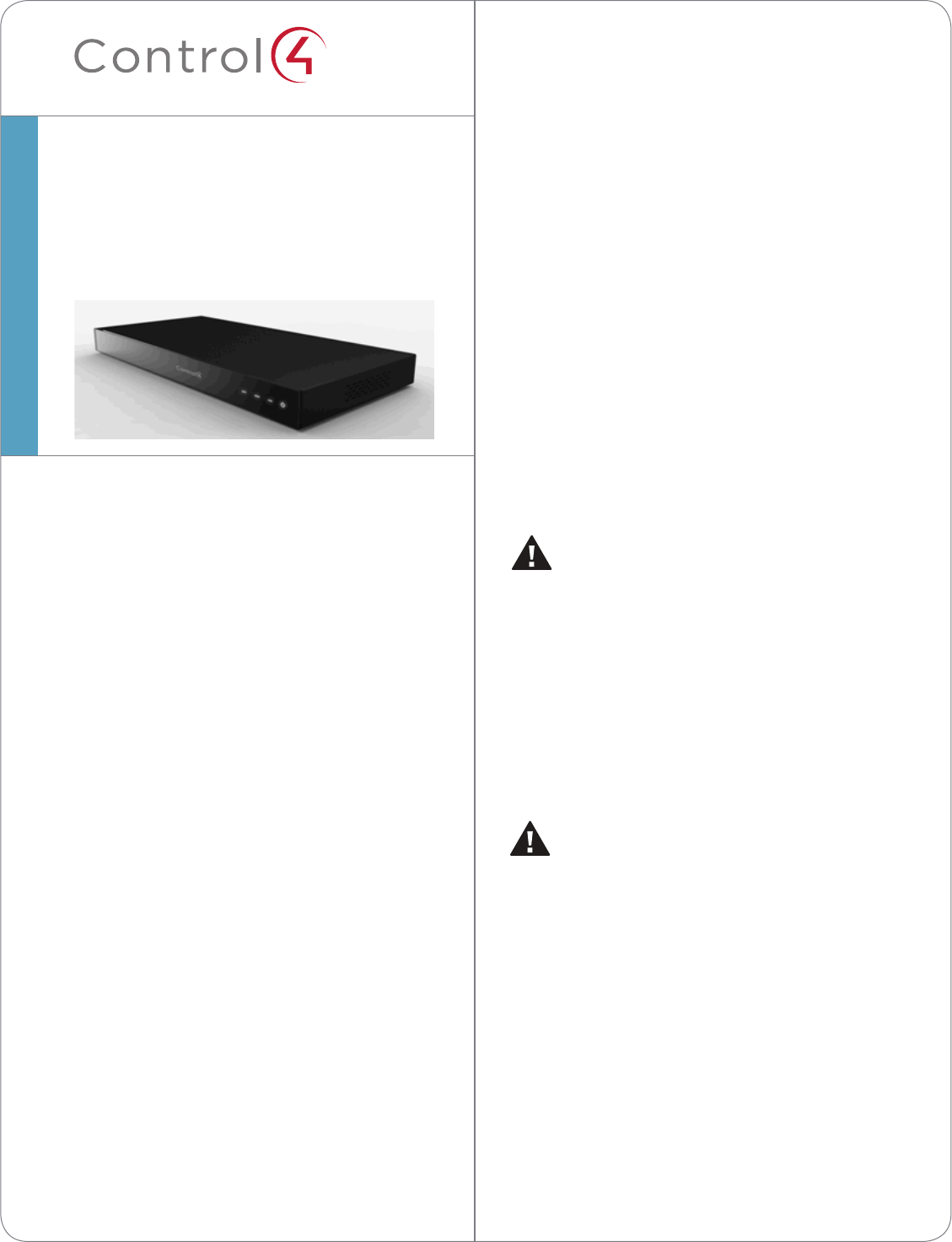
Introduction
The Control4® Home Controller HC-800 provides
many ways to control lights, home theaters,
distributed audio and video systems, and other
devices controlled using various protocols, for
example, IP, infrared (IR) Serial, Contact, and Relay.
This version comes with a faster processor, built-in
WiFi, HDMI for audio and video, improved ZigBee
radio, and more.
The HC-800 also provides extensive media
management services for audio and video sources,
for example, CDs, DVDs, or BluRays stored in
connected devices. It allows you to use an external
storage device with USB or eSATA support for media
storage, and it supports multi-zone audio capabilities,
sending music to rooms throughout the home. The
device installs on a rack or shelf, can be stacked, and
uses 1 RU rack space.
When you install and configure the Controller and
other system components (using Control4 Composer
software), your users can control the system using
one of two user interfaces included in this Controller:
On-Screen Navigator or a System Remote Control, or
any other Control4-supported user interface device
Home Controller
HC-800
Installation Guide
Draft
™
HC-800 Specifications
Model Number C4-HC800-BL
Network Ethernet—required
WiFi (only supported
when the unit is used as a
Secondary Controller)
Media Recognition Online CD/DVD/BluRay
recognition and media
information service
Audio Playback Formats MP3: 32kbps to 320kbps, CBR,
VBR, AAC, and FLAC
Display LED indicators
Power Requirements 100-240 VAC, 60/50 Hz, 0.26
A MAX
Dimensions H x W x D: 2.80” (71 mm) x
11.98” (304 mm) x 7.24” (184
mm)
Weight 4.7 pounds (xx kg)
Shipping Weight x.xx pounds (xx kg)
Additional Resources
The following resources are available for more
support.
• Your Control4 Reseller
• Control4 website: http://www.control4.com
• Composer documentation in online help or PDF
format available on the Dealer portal.
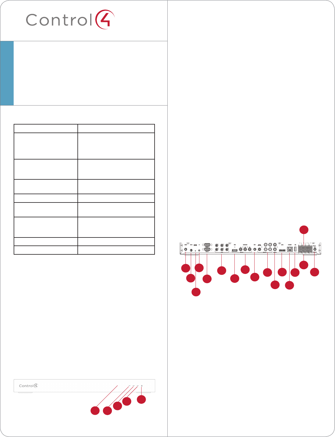
Front View
Figure 1. Front View
Home Controller
HC-800
Installation Guide
1 WiFi LED. This LED blinks first Red, then Orange,
and finally Blue during the boot process. When
the operating system starts running, the WiFi
driver changes the LED color depending on the
signal strength of its connection to its associated
access point. Colors and signal strength are as
follows: Orange=Fair to Good, Blue=Excellent,
and No Light=No connection.
2 Data LED. The Blue LED indicates that streaming
audio is received.
3 Link LED. The Blue LED indicates that the
Controller has been identified in a Control4
Composer project.
4 Power LED. The Blue LED indicates that AC
power is present. It turns on immediately after
power is applied to the Controller.
5 IR Window / IR Blaster—For capturing third-
party IR codes from hand-held devices (such as
remote controls) or blasting IR codes.
Back View
Connect all applicable devices to the HC-800 using
the connection options described next.
Figure 2. Back View
1 ZigBee. Antenna for the ZigBee radio.
2 Power Plug Port. AC power receptacle for the AC
to DC power cord.
3 Factory Restore Button. A recessed button that
restores the Controller to the factory defaults.
4 Identification Button. Easily-pressed button used
when identifying this device in Composer.
5 Serial. DB9 connectors for two (2) serial devices,
such as a receiver or disc changer. See “Connect
the Serial Ports” for more information.
6 IR Out. 3.5 mm jacks for up to six (6) IR output
transmitters. See “Set Up IR Emitters or IR
Blaster” for more information.
7 Video Out (HDMI). HDMI port for displaying
1
3
2
4
5
6
7
8
910
11
12
13
14
15
16
17
1234
5
Draft
* Home Controller 19Vdc, 3A
databases and Control4 system updates.
2 Mount options: The HC-800 is designed to be
stackable with other AV equipment or mount in a
rack or on a shelf using the options Rack Ear Kit
(C4-1UREK-B).
3 Connect the HC-800 to the network: To connect
using an Ethernet connection, plug the data
cable from the home network connection into the
Controller’s RJ-45 port (labeled “Ethernet”) and
the network port on the wall or at the network
switch.
Notes: (1) WiFi can only be used for Secondary
Controllers. (2) Only use the power supply
included in this box.
4 Power up the Controller: Plug the HC-800 power
cord (provided) into the Controller’s power plug
port and an electrical outlet.
Note: The HC-800 may take several minutes to
boot up and become operational. Please allow
sucient time for boot-up.
5 Connect system devices: Attach the devices as
described in “Connect the Devices” below.
6 Set up any external storage devices as described
in “Set up External Storage Device.”
Connect the Devices
Note: Use Composer to step through the
connection process before or after the physical
connections are completed.
The following section provides more information
about other connection options.
Use Pluggable Terminal Block
Connectors
For the Contact and Relay ports, the HC-800 makes
use of a pluggable terminal block connector—a
removable plastic part that locks in individual wires,
which is included.
To connect a device to the Pluggable Terminal Block:
navigation menus on a monitor or TV.
8 Video Out (Component). Component jack used
for displaying high-definition video.
9 WiFi 1. WiFi port to attach a WiFi antenna.
Note: WiFi cannot be used for Primary
Controllers; use for Secondary Controllers only.
10 Audio Out (2 left-right pairs). RCA jacks
for stereo channel line output (line level) for
amplifiers or audio switches. Includes one (1)
digital audio ouput and two (2) analog audio
outputs.
11 Audio In (1 left-right pair). RCA jacks for stereo
channel input (line level) for one (1) stereo analog
source.
12 eSATA. External serial ATA port for connecting a
hard drive to store media.
13 Ethernet. RJ-45 jack for a 10/100 BaseT Ethernet
connection.
14 USB. For external storage device with USB
support (such as FAT32-formatted devices). See
“Set up External Storage Device” for information.
15 Relay. Pluggable terminal block connector for
four (4) normally closed or normally opened
switchable connections. Provides power for small
devices (12V), signal input (SIG), and return path
(GND).
16 Contact. Pluggable terminal block connector
for four (4) normally closed or normally opened
switchable connections, such as a blind, a
fireplace, or a projector screen. The connectors
are for Normally Opened (NO), Normally Closed
(NC), and Common (COM).
17 WiFi 2. WiFi port to attach a WiFi antennae.
Note: WiFi cannot be used for Primary
Controllers; use for Secondary Controllers only.
See “Antenna Considerations” below.
Installation Instructions
To install this Controller:
1 Ensure that your home network is in place
before starting your system setup: The HC-800
requires a network connection (wired or WiFi)
to use all features as designed. When connected,
the Controller can connect to other IP devices on
the home network and access web-based media
Draft
1 Insert one of the wires required for your device
into the appropriate opening in the Pluggable
Terminal Block you reserved for that device (refer
to Figure 1 below). For example, if you add a
motion sensor, you would connect its wires to the
following Contact openings: power input to +12V
output signal to SIG, and ground connector to
GND. See the following sections for instructions
about connecting the various protocols.
2 Repeat Step 1 for all wires required for your
device.
Note: When you connect dry contact closure
devices, such as door switches, connect the
switch between +12V (Power) and SIG (Signal).
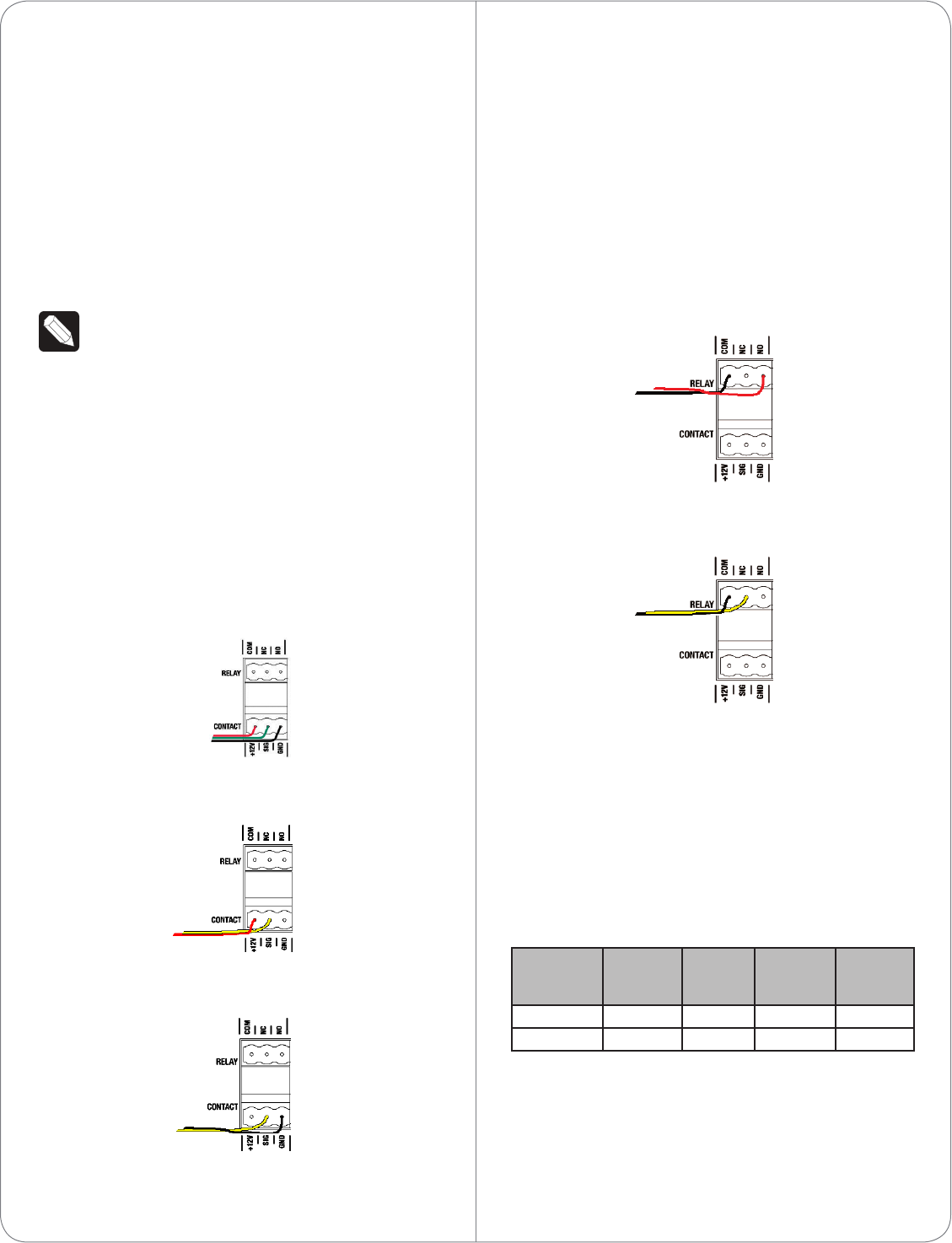
Connect to the Contact Port
The HC-800 provides four (4) contact ports for the
pluggable terminal block provided.
See the following figures to determine how to
connect the device to a contact port.
Figure 3. Contact Port for Voltage Source (e.g.,
Motion Sensor)
Figure 4. Contact for Dry Contact (e.g., Door Contact
Sensor)
Figure 5. Contact for Self-Powered Voltage Source
Device
Connect to the Relay Port
The HC-800 provides four (4) relay ports for
the pluggable terminal block provided. For most
applications, attach one (1) wire to the common
terminal and the other to the normally open terminal.
The relay switches close when the relay is activated.
The HC-800 can support applications that require a
normally closed contact.
Figure 6. Relay Port: Normally Open
Figure 7. Relay Port: Normally Closed
Connect the Serial Ports
The HC-800 has two (2) DB9-style serial ports.
Connect a device, for example, a receiver or disc
changer to the HC-800 by aligning the pins and
tightening the screws.
See the next table for serial communication values.
Hardware
Flow
Control
Odd
Parity
Even
Parity
No Parity
Serial Port 1 X X X
Serial Port 2 X X X X
Set Up IR Emitters or IR Blaster
Your system may contain third-party products
that are controlled with IR commands (usually
through remote controls). To provide a way for the
Draft

Controller to control a device that only recognizes IR
commands, complete one of the following setups:
• IR Emitters
• IR Blaster
IR Emitters
1 Plug the 3.5mm connector end of one of the six
(6) IR stick-on emitters provided into an IR Out
port on the HC-800.
2 Place the stick-on emitter end over the IR
receiver on the BluRay player, TV, or other target
device to drive IR signals from the HC-800 to the
target.
IR Blaster
In addition to IR emitters, the HC-800 is also
equipped with an IR blaster located just left of the
front LEDs.
To use the blaster rather than an IR emitter:
1 In Composer, connect the Front IR Out #6 of the
Controller to the IR In for the device you want to
control.
2 Test and verify that the HC-800 is positioned in
such a way that the blaster can reach the device
you want to control.
Antenna Considerations
Depending on the location of your HC-800 and the
network setup, you’ll need to consider which, if any,
antennas to connect to your HC-800.
On a Rack, Not Using ZigBee Access Point (ZAP)
In this case, the standard CAT5 Ethernet cable works
well with the HC-800 installed on a rack. No other
antenna is needed.
On a Rack, Using ZAP
In this case, if you’re HC-800 is installed on a rack,
you’ll need to purchase the Antenna Kit (C4-AK-
WIFI) and then use the External WiFi Antenna in that
kit. Connect the External WiFi Antenna to one of the
WiFi connectors on the back of the HC-800 (see
Figure 1, “Back View”).
Stacked, with an Ethernet Connection
In this case, if you have an HC-800 stacked with
other devices the standard CAT5 Ethernet cable
works well. No other antenna is needed.
Stacked, with a Wireless Connection
In this case, you’re stacking the HC-800 with other
devices and you’re connecting wirelessly.
1 Connect ? to the ZigBee port on the back of the
HC-800 (see Figure 1, “Back View”) unless you’re
not using this Controller as a ZAP. If you aren’t
using it as a ZAP, you don’t need the ZigBee
antenna.
2 Use the WiFi antenna when you don’t have an
Ethernet connection and you’re using the HC-
800 as a Secondary Controller.
Set Up External Storage Devices
You can store and access media from an external
storage device, for example, a network hard drive,
eSATA hard drive, or USB memory device by plug-
ging the USB drive into the USB port and configuring
or scanning the media in Composer.
Composer Driver Information
Choose the HC-800 driver in Composer and add it
to your project. If the correct driver doesn’t appear,
right-click a driver in the My Drivers tab, and select
Restore Default List to refresh the list. See Composer
Pro Getting Started for details.
Troubleshooting
Factory Restore Button
1 To restore the HC-800 for system recovery to
the factory default image, insert the end of a
paper clip into the small hole on the back of the
Controller labeled “Restore. “
2 Power cycle the device while pressing and
holding the Factory Restore button for about five
(5) to seven (7) seconds and until the Status LED
Draft

©2011 Control4. All rights reserved. Control4, the Control4 logo, the Control4 iQ logo and the Control4 certified logo are registered trademarks or trademarks of Control4 Corporation in
the United States and/or other countries. All other names and brands may be claimed as the property of their respective owners.
control4.com |
™
blinks Orange. This action starts the recovery
process.
Identification Button
1 To reset the HC-800 to the network defaults,
power cycle the device and hold the
Identification button until the Data, Link, and
Power LEDs are solid Blue. Immediately release
the button.
2 If during the boot sequence, the Status LED stays
Orange, press and hold the Identification button
until the LED blinks Blue, and then release it.
Power Button
If any time you plug in the Controller or it power
cycles but doesn’t reboot, press the Power button to
initiate the reboot it. See Figure 1, “Back View” for the
Power button’s location.
Regulatory/Safety Information
To review regulatory information for your particular
Control4 products, see the information located on
the Control4 website at: http://www.control4.com/
regulatory/.
Warranty
Limited 2-year Warranty. Go to http://www.control4.
com/warranty for details.
About This Document
Part number: 200-00241, Rev. A, 8/05/2011, Draft 4
FEDERAL COMMUNICATIONS COMMISSION INTERFERENCE STATEMENT
This equipment has been tested and found to comply with the limits for a Class B digital device,
pursuant to part 15 of the FCC Rules. These limits are designed to provide reasonable protection
against harmful interference in a residential installation. This equipment generates, uses and can
radiate radio frequency energy and, if not installed and used in accordance with the instructions, may
cause harmful interference to radio communications. However, there is no guarantee that interference
will not occur in a particular installation. If this equipment does cause harmful interference to radio or
television reception, which can be determined by turning the equipment off and on, the user is
encouraged to try to correct the interference by one or more of the following measures:
-Reorient or relocate the receiving antenna.
-Increase the separation between the equipment and receiver.
-Connect the equipment into an outlet on a circuit different from that to which the receiver is connected.
-Consult the dealer or an experienced radio/ TV technician for help.
CAUTION:
Any changes or modifications not expressly approved by the grantee of this device could void the
user's authority to operate the equipment.
Labeling requirements
This device complies with Part 15 of the FCC Rules. Operation is
subject to the following two conditions: (1) this device may not cause
harmful interference, and (2) this device must accept any interference
received, including interference that may cause undesired operation.
RF exposure warning
This equipment must be installed and operated in accordance with provided instructions and
the antenna(s) used for this transmitter must be installed to provide a separation distance of at
least 20 cm from all persons and must not be co-located or operating in conjunction with any
other antenna or transmitter. End-users and installers must be provide with antenna
installation instructions and transmitter operating conditions for satisfying RF exposure
compliance.
Canada, Industry Canada (IC) Notices
This Class B digital apparatus complies with Canadian ICES-003 and RSS-210. Operation is subject to
the following two conditions: (1) this device may not cause interference, and (2) this device must
accept any interference, including interference that may cause undesired operation of the device.
Radio Frequency (RF) Exposure Information
The radiated output power of the Wireless Device is below the Industry Canada (IC) radio frequency
exposure limits. The Wireless Device should be used in such a manner such that the potential for human
contact during normal operation is minimized.

This device has also been evaluated and shown compliant with the IC RF Exposure limits under mobile
exposure conditions. (antennas are greater than 20cm from a person's body).
This device has been certified for use in Canada. Status of the listing in the Industry
Canada’s REL (Radio Equipment List) can be found at the following web address:
http://www.ic.gc.ca/app/sitt/reltel/srch/nwRdSrch.do?lang=eng
Additional Canadian information on RF exposure also can be found at the following web address:
http://www.ic.gc.ca/eic/site/smt-gst.nsf/eng/sf08792.html
Canada, avis d'Industry Canada (IC)
Cet appareil numérique de classe B est conforme aux normes canadiennes ICES-003 et RSS-210.
Son fonctionnement est soumis aux deux conditions suivantes : (1) cet appareil ne doit pas causer
d'interférence et (2) cet appareil doit accepter toute interférence, notamment les interférences qui peuvent
affecter son fonctionnement.
Informations concernant l'exposition aux fréquences radio (RF)
La puissance de sortie émise par l’appareil de sans fil est inférieure à la limite d'exposition aux
fréquences radio d'Industry Canada (IC). Utilisez l’appareil de sans fil de façon à minimiser les contacts
humains lors du fonctionnement normal.
Ce périphérique a également été évalué et démontré conforme aux limites d'exposition aux RF d'IC dans
des conditions d'exposition à des appareils mobiles (les antennes se situent à moins de 20 cm du corps
d'une personne).
Ce périphérique est homologué pour l'utilisation au Canada. Pour consulter l'entrée correspondant à
l’appareil dans la liste d'équipement radio (REL - Radio Equipment List) d'Industry Canada rendez-vous
sur:
http://www.ic.gc.ca/app/sitt/reltel/srch/nwRdSrch.do?lang=eng
Pour des informations supplémentaires concernant l'exposition aux RF au Canada rendez-vous sur :
http://www.ic.gc.ca/eic/site/smt-gst.nsf/eng/sf08792.html