Snap One C4KC CONFIGURABLE KEYPAD WITH ZIGBEE User Manual
Control4 CONFIGURABLE KEYPAD WITH ZIGBEE
Snap One >
USER MANUAL
™
WARNING! Improper use or installation can cause SERIOUS INJURY,
DEATH or LOSS/DAMAGE OF PROPERTY.
WARNING! If you are unsure about any part of these instructions, consult
a qualified electrician.
WARNING! To reduce the risk of SERIOUS INJURY or DEATH, turn OFF
local electrical power before installing this product, and before installing,
removing, or replacing keycaps.
WARNING! Use this device only with copper or copper-clad wire. Do not
use aluminum wiring. This product has not been approved for use with
aluminum wiring.
WARNING! This device must be protected by a circuit breaker (20A max).
IMPORTANT! Using this product in a manner other than outlined in this
document voids your warranty. Further, Control4 is NOT liable for any
damage incurred with the misuse of this product. See “Troubleshooting.”
IMPORTANT! Do NOT use a power screwdriver to install this device. If you
do, you may overtighten the screws and strip them. Also, overtightening
the screws may interfere with proper button operation.
IMPORTANT! This is an electronic device with intricate components.
Handle and install with care!
Installation Instructions
1 Ensure that the location and intended use meet the following criteria:
• When replacing a traditional 3-way switch, refer to the “Two-Location”
sample wiring configurations provided in the appropriate load control device
installation guide.
• Install in accordance with all national and local electrical codes.
• The range and performance of the wireless control system is highly
dependent on the following: (1) distance between devices; (2) layout of the
home; (3) walls separating devices; and (4) electrical equipment located near
devices.
WARNING! To reduce the risk of SERIOUS INJURY or DEATH,
turn OFF local electrical power before installing this product.
2 Turn o the local electrical power by either switching o the circuit breaker or
removing the fuse from the fuse box. To ensure the wires do NOT have power
running to them, use an inductive voltage detector.
WARNING! As with any electrical device, improper use or installation can
cause SERIOUS INJURY or DEATH. It is important that you understand the
particular wiring configuration of your installation before proceeding.
NOTE: The wallbox wiring shown in this document is an example. Your
wire colors and functions may dier. If you are not sure which wires are
the Hot, Neutral, and Ground wires, have a trained electrician do the
installation.
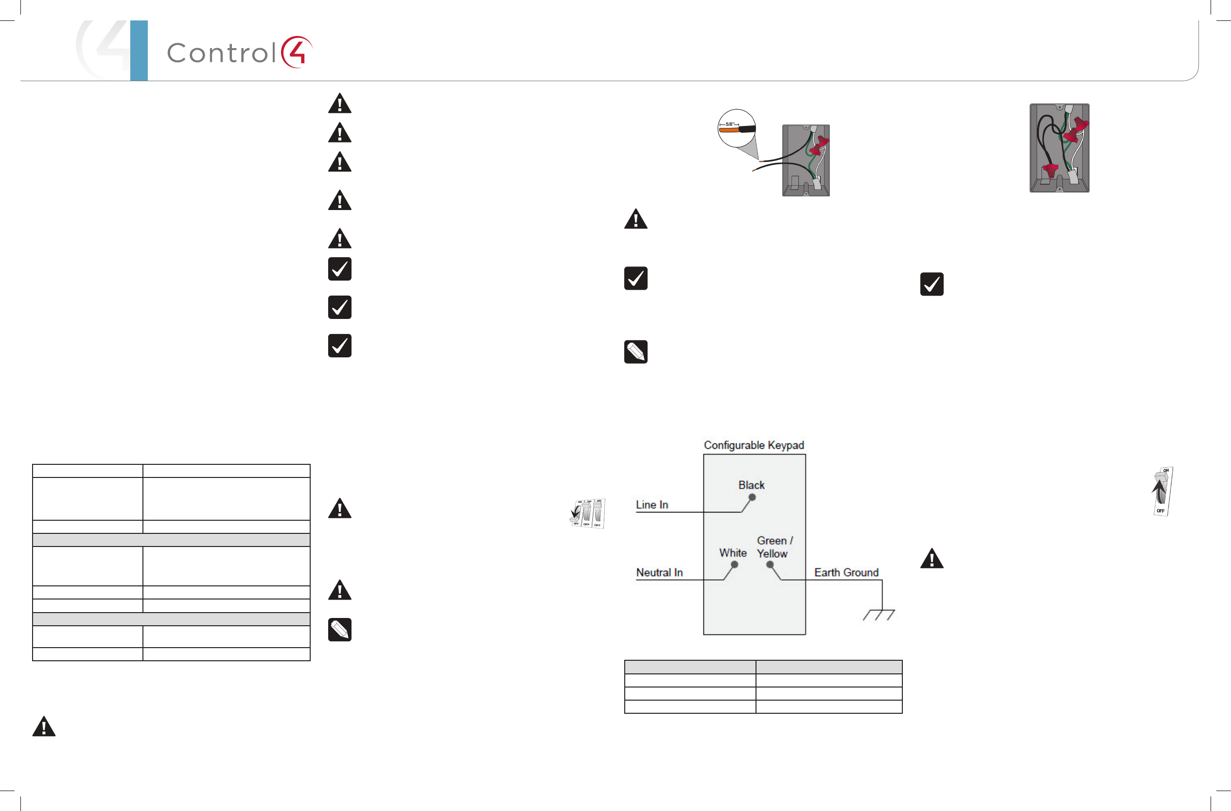
3 Prepare each wire. Wire insulation should be stripped back 5/8 of an inch
from the wire end (see Figure 1).
Supported Model
• C4-KC120277 Wireless Configurable Keypad
Introduction
The Control4® Wireless Configurable Keypad is intended for use in a Control4
system. It installs in a standard wall box using typical wiring standards and
communicates to the Control4 system using a wireless connection.
Box Contents
• Wireless Configurable Keypad
• Button Kit
• Wire Nuts
• Warranty Card
• WirelessCongurableKeypadInstallationGuide (this document)
Specifications
The specifications are described below.
Model Number C4-KC120277-xx
Power Requirements 110-277 VAC +/-10% 50/60 Hz
This device requires a neutral AC
connection.
Power Consumption 1 W
Environmental
Operational Temperature 32˚ F - 104˚ F (0˚ C - 40˚ C)
All load ratings are based on an ambient
temperature of 25˚ C.
Humidity 5% to 95% non-condensing
Storage -4˚ F - 158˚ F (-20˚ C - 70˚ C)
Miscellaneous
Control Communications ZigBee, IEEE 802.15.4, 2.4 GHz, 15-channel
spread spectrum radio
Wallbox Volume 4.75 cubic inches
Warnings and Considerations
WARNING! This device must be installed by a licensed electrician in
accordance with all national and local electrical codes.
Configurable
Keypad
Installation Guide
Figure 1. Strip Wire Insulation
WARNING! Ground the keypad in accordance with the National Electric
Code (NEC) requirements. DO NOT rely solely upon the yoke plate’s
contact with a metal wallbox for adequate grounding. Use the keypad’s
ground wire to make a secure connection to the safety ground of the
electrical system.
IMPORTANT! Not grounding this product according to the preceding
may result in an installation less immune to damage caused by electrical
disturbances, such as ESD or lightning, and may void the warranty.
4 Identify and connect the keypad wires to the wallbox wires using the wire
nuts.
NOTE: Wallbox wires can dier depending upon how the box was wired
by your electrician.
5 To wire the keypad, connect and cap the wires with a wire nut as indicated in
the following figure and table.
Figure 2. Keypad Wiring
Configurable Keypad Wires Wires in Wall Box
White (neutral) White (neutral)
Green (ground) Green (ground)
Black (hot) Black (hot)
6 Fit the wires back into the wallbox. Bend the wires in a zigzag pattern so that
they easily fold into the wallbox (Figure 3).
Figure 3. Bend the Wires
7 If you are using a Control4 push-on (screwless) wall plate:
a. Align the keypad to the wallbox (the model # label should be at the
bottom) and fasten it with screws. Tighten the screws until the back
side of the yoke plate is even with the wall surface, but no further.
Overtightening can warp the configurable keypad and cause
mechanical malfunction.
TIP: In multi-gang installations, leave the screws that attach the keypad
to the wallbox slightly loose until the faceplate’s sub-plate is attached
to all the devices. This allows all devices in the multi-gang box to be
aligned before securing them to the wallbox. See the Control4 Faceplate
Installation Guide for details.
b. Install the Top Actuator Bar, Bottom Sensor Bar, and Button Keycaps
following the instructions in the “Keycap Installation” section below.
c. Install the Control4 Faceplate following the instructions in the
Faceplate Installation Guide.
8 If you are using a Decora-style screw-on wall plate:
a. Align the keypad to the wallbox and fasten it with screws.
b. Tighten the screws until the back side of the yoke plate is even with
the wall surface but no further. Overtightening can warp the keypad
and cause mechanical malfunction.
c. Install the Top Actuator Bar, Bottom Sensor Bar, and Button Keycaps
following the instructions in the “Keycap Installation” section below.
d. Fasten the faceplate to the keypad with screws.
9 Turn ON power at the circuit breaker or replace the fuse
from the fuse box.
10 Ensure that all LEDs on the front are lit.
Keycap Installation
WARNING! To reduce the risk of SERIOUS INJURY or DEATH, turn OFF
the local electrical power before installing, removing, or replacing the
keycaps.
To install the keycaps:
1 Turn o the local electrical power.
2 If previously installed, remove the faceplate and sub-plate from the keypad.
3 Snap the Top Actuator Bar onto the top of the keypad.
4 Snap the Bottom Sensor Bar onto the keypad.
5 Snap the Button Keycaps onto the keypad in the desired configuration.
6 To remove the Top Actuator Bar, Bottom Sensor Bar, or Button Keycaps,
simply grip the bar or keycap lightly from the right and left sides and pull out.
DO NOT pry it o with a screwdriver.
Operation and Configuration
On initial power up, all LEDs on the keypad will illuminate green indicating that the
device has power. Until the keypad has been configured into a Control4 system,
it will not control any loads. To set up this keypad for use with a Control4 system,
refer to the Composer Pro User Guide.
™
Button tap sequences:
The button tap sequences are defined in the table below. Button tap sequences
that require a single (1) button should use the top-most button installed on the
keypad. Button tap sequences requiring two (2) buttons should use the top-most
and bottom-most buttons installed on the keypad.
Function Sequence Button
Identify 4
ZigBee Channel 7
Reboot 15
Factory Reset 9-4-9
Leave Mesh and Reset 13-4-13
Troubleshooting
If one or more Light Emitting Diodes (LEDs) are not lit:
• Ensure circuit breaker is not turned OFF or tripped.
• Check for proper wiring (see Step 2 in “Installation Instructions”). You may
also need to contact a trained electrician.
• For help on the installation or operation of this product, email or call the
Control4 Technical Support Center. Please provide your exact model number.
Contact support@control4.com or see the web site www.control4.com.
Care and Cleaning
• Do NOT paint the keypad or its wall plate.
• Do NOT use any chemical cleaners to clean the keypad.
• Clean surface of the keypad with a soft damp cloth as needed.
Regulatory/Safety Information
To review Regulatory information for your particular Control4 products, see
the information located on the Control4 website at: http://www.control4.com/
regulatory/.
Warranty
For complete warranty information, including details on consumer legal rights as
well as warranty exclusions, review the Warranty card or visit www.control4.com/
warranty.
About this Document
Part Number: 200-00309, Rev A 11/09/2012
Copyright ©2013 Control4. . All rights reserved. Control4, the Control4 logo, the Control4 iQ logo and the Control4 certified logo are registered trademarks or trademarks of Control4 Corporation in
the United States and/or other countries. All other names and brands may be claimed as the property of their respective owners Pricing and specifications are subject to change without notice

Regulatory Compliance & Safety Information for Contol4 Model C4-KC120277 & C4-KC240.
Electrical Safety Advisory
Important Safety Information
Read the safety instructions before using this product.
1. Read these instructions.
2. Keep these instructions.
3. Heed all warnings.
4. Follow all instructions.
5. Do not use this apparatus near water.
6. Clean only with dry cloth.
7. Do not block any ventilation openings. Install in accordance with the manufacturer’s
instructions.
8. Do not install near any heat sources such as radiators, heat registers, stoves, or other
apparatus (including amplifiers) that produce heat.
9. Do not defeat the safety purpose of the polarized or grounding-type plug. A polarized
plug has two blades with one wider than the other. A grounding type plug has two blades
and a third grounding prong. The wide blade or the third prong is provided for your safety.
If the provided plug does not fit into your outlet, consult an electrician for replacement of
the obsolete outlet.
10. Protect the power cord from being walked on or pinched particularly at plugs,
convenience receptacles, and the point where they exit from the apparatus.
11. Only use attachments/accessories specified by the manufacturer.
12. Use only with the cart, stand, tripod, bracket, or table specified by the manufacturer, or
sold with the apparatus. When a cart is used, use caution when moving the
cart/apparatus combination to avoid injury from tip-over.
13. Unplug this apparatus during lightning storms or when unused for long periods of time.
This equipment uses AC power which can be subjected to electrical surges, typically
lightning transients which are very destructive to customer terminal equipment connected
to AC power sources. The warranty for this equipment does not cover damage caused
by electrical surge or lightning transients. To reduce the risk of this equipment becoming
damaged it is suggested that the customer consider installing a surge arrestor.
14. Refer all servicing to qualified service personnel. Servicing is required when the
apparatus has been damaged in any way, such as power-supply cord or plug is
damaged, liquid has been spilled or objects have fallen into the apparatus, the apparatus
has been exposed to rain or moisture, does not operate normally, or has been dropped.
15. Use the circuit breaker to disconnect the apparatus from the AC mains. The circuit
breaker shall remain readily accessible.
16. To completely disconnect unit power from the AC mains, turn off the circuit breaker. To
reconnect power, turn on the circuit breaker following all safety instructions and
guidelines.
17. This product relies on the buildings installation for short-circuit (overcurrent) protection.
Ensure that the protective device is rated not greater than: 20A.
18. CAUTION: As with all batteries, there is a risk of explosion or personal injury if the
battery is replaced by an incorrect type. Dispose of used battery according to the
instructions of the battery manufacturer and applicable environmental guidelines. Do not
open, puncture or incinerate the battery, or expose it to conducting materials, moisture,
liquid, fire or heat above 54° C or 130° F.
19. Never push objects of any kind into this product through cabinet slots as they may touch
dangerous voltage points or short out parts that could result in fire or electric shock.
20. This product can interfere with electrical equipment such as tape recorders, TV sets,
radios, computers and microwave ovens if placed in close proximity.
The lightning flash and arrow head within the triangle is a warning sign alerting
you of dangerous voltage inside the product
Caution: To reduce the risk of electric shock, do not remove cover (or back). No
user serviceable parts inside. Refer servicing to qualified service personnel.
The exclamation point within the triangle is a warning sign alerting you of
important instructions accompanying the product.
See marking on bottom / back of product
Warning!: To reduce the risk of electrical shock, do not expose this
apparatus to rain or moisture
AVERTISSEMENT! Pour réduire le risque de choc électrique,
n'exposez pas cet appareil à la pluie ou à l'humidité.
WARNUNG! Um das Risiko des elektrischen Schlages zu verringern,
setzen Sie diesen Apparat nicht Regen oder Feuchtigkeit aus.
Save these instructions
Compliance of this equipment is confirmed by the following label that is placed on the equipment:
USA & Canada Compliance
FCC Part 15, Subpart B / ICES-003Unintentional Emissions Interference Statement
This equipment has been tested and found to comply with the limits for a Class B digital device,
pursuant to Part 15 of the FCC rules and Industry Canada ICES-003. These limits are designed
to provide reasonable protection against harmful interference when the equipment is operated in
a residential installation. This equipment generates uses and can radiate radio frequency energy
and, if not installed and used in accordance with the instructions, may cause harmful interference
to radio communications. However, there is no guarantee that interference will not occur in a

particular installation. If this equipment does cause harmful interference to radio or television
reception, which can be determined by turning the equipment off and on, the user is encouraged
to try to correct the interference by one or more of the following measures:
Reorient or relocate the receiving antenna.
Increase the separation between the equipment and receiver.
Connect the equipment into an outlet on a circuit different from that to which the receiver
is connected.
Consult the dealer or an experienced radio/TV technician for help.
This device complies with part 15 of the FCC rules and Industry Canada ICES-003. Operation is
subject to the following two conditions: (1) This device may not cause harmful interference, and
(2) this device must accept any interference received, including interference that may cause
undesired operation.
Le présent appareil est conforme aux CNR d’Industrie Canada applicables aux appareils radio
exempts de licence. L’exploitation est autorisée aux deux conditions suivantes : (1) l’appareil ne
doit pas produire de brouillage, et (2) l’utilisateur de l’appareil doit accepter tout brouillage
radioélectrique subi, même si le brouillage est susceptible d’en compromettre le fonctionnement.
IMPORTANT! Any changes or modifications not expressly approved by the party responsible for
compliance could void the user’s authority to operate this equipment.
IMPORTANT! Tous les changements ou modifications pas expressément approuvés par la partie
responsable de la conformité ont pu vider l’autorité de l’utilisateur pour actionner cet équipement.
FCC Part 15, Subpart C / RSS-210 Intentional Emissions Interference Statement
Compliance of this equipment is confirmed by the following certification numbers that are placed
on the equipment:
Notice: The term “FCC ID:” and “IC” before the certification number signifies that FCC and
Industry Canada technical specifications were met.
FCC ID: R33C4KC
IC: 7848A-C4KC
This equipment must be installed by qualified professionals or contractors in accordance with
FCC Part 15.203 & IC RSS-210, Antenna Requirements. Do not use any antenna other than the
one provided with the unit.
RF Radiation Exposure Statement
This equipment complies with the FCC/IC radiation exposure limits set fourth for portable
transmitting devices operation in an uncontrolled environment. End users must follow the specific
operating instructions to satisfy RF exposure compliance.
The equipment should only be used or installed at locations where there is normally at
least a 20cm separation between the antenna and all persons.
This transmitter must not be co-located or operation in conjunction with any other
antenna or transmitter.
Any changes or modifications not expressly approved by the party responsible for
compliance could void the user’s authority to operate this equipment.

European Compliance
Conformity of the equipment with the guidelines below is attested by the application of the CE
mark.
CE Declaration of Conformity
Manufacturer’s Name: CONTROL4 CORPORATION
Manufacturer’s Address: 11734 S. ELECTION ROAD SUITE 200
SALT LAKE CITY
UT 84020 USA
EU Representative Name: CONTROL4 EMEA LIMITED
EU Representative Address: UNIT3, GREEN PARK BUSINESS CENTRE
SULTON-ON-THE FOREST
YORK YO61 IET, UNITED KINGDOM
Product Name(s): Configurable Keypad
Brand: Contol4
Model(s): C4-KC240
Product Standard(s) to which Conformity of the Council Directive(s) is declared:
EMC - 2004/108/EC “Electromagnetic Compatibility (EMC) Directive”:
(Emissions) EN 55022:2010, (Immunity) EN 55024:1998, EN 301 489-1:2008, EN 301 489-
17:2009, EN 61000-3-2:2004 & EN 61000-3-3:2002
Safety – 206/95/EC “Low Voltage Directive (LVD)”:
EN 60669-2-1 .
Telecom & Radio - 1999/5/EC Radio equipment and Telecommunications Terminal
Equipment (R&TTE) Directive:
EN 300 328 V1.7.1 (2006-10)
RoHS - 2002/95/EC Restriction of the Use of certain Hazardous Substances in Electrical
and Electronic Equipment (EEE) & WEEE - 2002/96/EC Waste of Electrical and Electronic
Equipment (EEE).
We, the undersigned, hereby declare that the equipment specified above conforms to the above
directives and standards. Date of Issue: January 11, 2013
Legal Representative
Signature
Roger Midgley
Sr. Regulatory Compliance Engineer
Recycling
Control4 understands that a commitment to the environment is essential for a health life and
sustainable growth for future generations. We are committed to supporting the environmental
standards, laws, and directives that have been put in place by various communities and countries
that deal with concerns for the environment. This commitment is represented by combining
technological innovation with sound environmental business decisions.
WEEE Compliance
Control4 is committed to meeting all requirements of the Waste Electrical and Electronic
Equipment (WEEE) directive (2002/96/EC). The WEEE directive requires the manufacturers of
electrical and electronic equipment who sell in EU countries: (1) label their equipment to notify
customers that it needs to be recycled, and (2) provide a way for their products to be
appropriately disposed of or recycled at the end of their product lifespan. For collection or
recycling of Control4 products, please contact your local Control4 representative or dealer.
Australia / New Zealand Compliance
Compliance of this equipment is confirmed by the following label that is placed on the equipment:
About this Document
Copyright © 2012 Control4 Corporation. All rights reserved. Control4 and the Control4 logo are
registered trademarks or trademarks of Control4 Corporation in the United States and/or other countries.
Part Number 200-00??? Rev A, 1/1/2013