Snap One C4KP3Z Wireless Keypad User Manual 200 00037 Rev A Wireless2 3 6 ButtonKeypad
Control4 Wireless Keypad 200 00037 Rev A Wireless2 3 6 ButtonKeypad
Snap One >
Exhibit 8
Wireless 2, 3, and 6-Button
Keypad Installation Guide
Supported Models and Requirements
C4-KP2-Z-x Wireless 2-Button Keypad
C4-KP3-Z-x Wireless 3-Button Keypad
C4-KP6-Z-x Wireless 6-Button Keypad
This device requires a neutral AC connection.
Specifications
This multi-button keypad is intended for use in a Control4® system. It installs
in a standard wall box using typical wiring standards and communicates to
the Control4 system using a wireless connection. The specifications are
described below.
WARNING! To reduce the risk of SERIOUS INJURY or DEATH, turn
OFF local electrical power before installing this product, and before
installing, removing, or replacing keycaps.
IMPORTANT! Using this product in a manner other than outlined in
this document voids your warranty. Further, Control4 is NOT liable for
any damage incurred with the misuse of this product. See “Limited 2
Year Warranty.”
IMPORTANT! Do NOT use a power screw driver to install this device.
If you do, you may overtighten the screws and strip them.
IMPORTANT! This is an electronic device with intricate components.
Handle and install with care!
Installation Instructions
1 Ensure that the location and intended use meet the following criteria:
• When replacing a traditional 3-way switch, refer to the “Two-Location” sample
wiring configurations provided in the following documents:
Wireless Dimmer Installation Guide
Wireless Switch Installation Guide
• Install in accordance with all national and local electrical codes.
• The required wall box size is specified by the NEC (National Electrical Code).
The internal wall box volume occupied by this multi-button keypad is 5.0
cubic inches.
• The range and performance of the wireless control system is highly
dependent on the following: (1) distance between devices; (2) layout of the
home; (3) walls separating devices; and (4) electrical equipment located near
devices.
• If you are planning to use engraved keycaps for 3-Button and 6-Button
Keypads, DO NOT continue until you have read the “Replace Keycaps”
section.
• If installing a multi-button keypad in a multi-gang installation, DO NOT
continue until you have read the “Multi-Gang Installations” section.
WARNING! To reduce the risk of SERIOUS
INJURY or DEATH, turn OFF local electrical
power before installing this product.
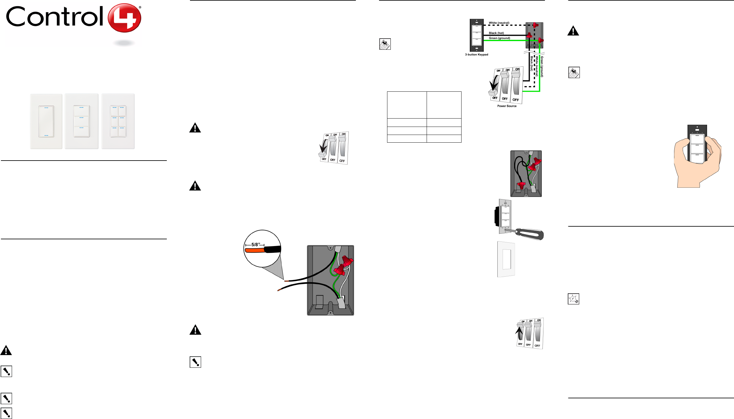
2 Turn off the local electrical power by either
switching off the circuit breaker or removing the
fuse from the fuse box. To ensure the wires do NOT
have power running to them, use an inductive
voltage detector.
WARNING! As with any electrical device, improper use or
installation can cause SERIOUS INJURY or DEATH. It is important
that you understand the particular wiring configuration of your
installation before proceeding. Note: The wall box wiring shown in
this document is an example. Your wire colors and functions may
differ. If you are not sure which wires are the Hot, Neutral, and
Ground wires, have a trained electrician do the installation.
3 Prepare each
wire. Wire
insulation should
be stripped back
5/8 of an inch
from the wire end
(as shown).
WARNING! Ground the Wireless Keypad in accordance with the National
Electric Code (NEC) requirements. Although the keypad's aluminum yoke plate
and green ground wire are directly bonded together inside the keypad, DO
NOT rely solely upon the yoke plate's contact with a metal wall box for
adequate grounding. Use the keypad’s ground wire to make a secure
connection to the safety ground of the electrical system.
IMPORTANT! Not grounding this product according to the preceding may
result in an installation less immune to damage caused by electrical
disturbances, such as lightning, and void the warranty.
4 If you need to “Replace Keycaps” or do “Multi-Gang Installations”, then
refer to those sections (to the right) before continuing.
5 Identify and connect the
multi-button keypad wires to the
wall box wires using wire nuts.
Note: Wall box wires can
differ depending upon how
the box was wired by your
electrician.
To wire the multi-button keypad,
connect and cap with a wire nut
the wires indicated in the
following table.
6 Fit wires back into the wall box. Bend the wires in a
zigzag pattern so that they easily fold into the wall
box.
7 If you are using the Control4 push-on (screw-less)
wall plate that shipped with your multi-button
keypad:
a. Align the multi-button keypad to the wall
box and fasten with screws. Tighten the
screws until the back side of the metal
yoke plate is even with the wall surface,
but no farther. Overtightening can warp
the multi-button keypad and cause
mechanical malfunction.
b. With the wall plate’s removal slot facing
down, push the wall plate onto the
dimmer’s black plastic sub-plate.
8 If you are using a Decora-style screw-on wall
plate:
a. Remove the multi-button keypad’s black
plastic sub-plate and store it for future use (in case you later
decide to use the Control4 wall plate).
b. Align the multi-button keypad to the wall box and fasten with
screws.
c. Fasten the wall plate to the multi-button keypad
with screws.
9 Turn ON power at the circuit breaker or replace fuse
from fuse box.
10 Ensure that all LEDs on the front are lit.
Replace Keycaps
Applies to 3-Button and 6-Button Keypads Only
WARNING! To avoid SERIOUS INJURY or DEATH, turn OFF local
electrical power before installing, removing, or replacing keycaps.
Control4 offers standard engraved keycaps and custom engraved keycaps
(both sold separately) to enable you to personalize 3-Button and 6-Button
Keypads.
Note: Custom engraving is not available for 2-Button Keypads.
If you are replacing keycaps:
1. Turn off local electrical power.
2. Remove the screw-less or screw-on wall plate from the multi-button key-
pad.
3. Remove the black plastic sub-plate from the multi-button keypad by
removing the screw at the top and bottom of the device.
4. Pinch both sides of the keycap
retainer at both ends—working first at
the top, then the bottom—to gently
remove the retainer. DO NOT pry the
retainer off with a screw driver.
5. Remove the default keycaps from the
keycap retainer and replace each one
with the engraved keycap of your
choice. Be sure to place the LED at
the top.
6. Carefully snap the retainer back into
place, taking care not to damage the
retainer clips.
7. Reattach the sub-plate with the screws.
8. Reattach the wall plate.
Multi-Gang Installations
Multi-gang installations are configurations in which 2 or more devices are
installed side-by-side in the same wall box. For multi-gang installations:
If using a Control4 push-on (screw-less) multi-gang wall plate:
Remove the individual black plastic sub-plate from each device and replace
them with the multi-gang sub-plate that shipped with your Control4 multi-
gang wall plate. The use of the multi-gang sub-plate inherently aligns and
spaces each device properly.
TIP: For ease of installation, each device’s yoke plate must be even
and aligned in a flat plane so that the multi-gang sub-plate can sit flat
against all of the devices. This can be accomplished by initially not
screwing the devices tightly against the wall box, leaving about 1/8 of
an inch gap between the wall and the yoke plates. This allows each
device to move and conform to the sub-plate. Using the new screws
supplied with the multi-gang sub-plate, secure the multi-gang sub-
plate to all devices to create a single structure. Then secure the
structure by tightening the wall box screws the remaining 1/8 of an
inch. Do not over-tighten any of the screws or you will misalign the
flat plane of the multi-gang wall plate.
If using a Decora-style screw-on multi-gang wall plate:
Remove the black plastic sub-plate from each device, just as you would for a
single device (see step 8), and store it for future use in case you later decide
to use the Control4 wall plate.
Operation and Configuration
On initial power up, the unit will flash the Red/Green/Blue (RGB) LEDs,
which can be programmed with different colors for different states or color
preferences. To set up this multi-button keypad for use with a Control4
system, refer to your system setup documentation.
Power: 120 V~, 60/50 Hz, 490 mW
Supported Load
Types:
Not Applicable. This device does not directly
control a load.
Communications: IEEE 802.15.4, 2.4 GHz, 15-channel, spread
spectrum radio
Multi-Button
Keypad Wires
(2, 3, or 6-
Button)
Wires in
Wall Box
White (neutral) White (neutral)
Green (ground) Green (ground)
Black (hot) Black (hot)

Troubleshooting
If one or more Light Emitting Diodes (LEDs) are not lit:
•Ensure circuit breaker is not turned OFF or tripped.
•Check for proper wiring, such as the example in step 5. You may also need to
contact a trained electrician.
•For help on the installation or operation of this product, email or call the
Control4 Technical Support Center. Please provide your exact model number.
Contact support@control4.com or see the web site www.control4.com.
Care and Cleaning
•Do NOT paint the multi-button keypad or its wall plate.
•Do NOT use any chemical cleaners to clean the multi-button keypad.
•Clean surface with a soft damp cloth as needed.
Regulatory Compliance
This product complies with standards established by the following regulatory
bodies:
•Federal Communications Commission (FCC)
•Industry Canada
•Underwriters Laboratories Inc. (UL)
FCC
FCC ID:
R33C4KP3Z (Models C4-KP2-Z-x and C4-KP3-Z-x)
R33C4KP6Z (Model C4-KP6-Z-x)
This device complies with Part 15 of the FCC Rules. Operation is subject to
the following two conditions: (1) this device may not cause harmful
interference, and (2) this device must accept any interference received,
including interference that may cause undesired operation.
This equipment has been tested and found to comply with the limits for a
Class B digital device, pursuant to Part 15 of the FCC Rules. These limits are
designed to provide reasonable protection against harmful interference in a
residential installation. This equipment generates, uses, and can radiate
radio frequency energy and, if not installed and used in accordance with the
instructions, may cause harmful interference to radio communications.
However, there is no guarantee that interference will not occur in a particular
installation. If this equipment does cause harmful interference to radio or
television reception, which can be determined by turning the equipment off
and on, the user is encouraged to try to correct the interference by one or
more of the following measures:
•Reorient or relocate the receiving antenna.
•Increase the separation between the equipment and receiver.
•Connect the equipment into an outlet on a circuit different from that to which
the receiver is connected.
•Consult the dealer or an experienced radio/TV technician for help.
IMPORTANT! Changes or modifications not expressly approved by
Control4 could void the user’s authority to operate the equipment.
ETL Statement
ETL Control Number: 3129831
This product has been tested by ETL and was found to comply with the Standard for
Safety for Industrial Control Equipment:
•UL/ANSI Standard 508 (Seventeenth Edition)
•CSA Standard C22.2 No. 14-05
Limited 2 Year Warranty
Control4 Corporation ("Control4") warrants that at the time of first-consumer sale, this
product will be free from defects in material and manufacture. Control4 further warrants
that for a period of 2 years (24 months) after initial consumer sale, the product will
function in accordance with its specification, provided that it is installed and maintained
under normal and proper use. This warranty extends only to products purchased directly
from Control4 or an Authorized Control4 Reseller. If the product proves to be defective
in material or workmanship during the warranty period, it may be returned to the place of
purchase and Control4 will, at its sole option, repair or replace the product with a like
product. This warranty provides the consumer purchaser with specific legal rights, which
may vary per state or country. For complete warranty information, including details on
consumer legal rights as well as warranty exclusions, visit www.control4.com/warranty.
About this Document
United States Patents Pending. Copyright © 2008 Control4 Corporation.
Control4 and the Control4 logo are registered trademarks of Control4
Corporation. All trademarks are properties of their respective owners. Part
Number: 200-00037 Rev B
Industry Canada
This Class B digital apparatus complies with Canada ICES-003.
Cet appareil numérique de la classe B est conforme à la norme NMB-003 du
Canada.
CAN/CSA-C22.2 No. 14-05 (Industrial Control Equipment)
Operation is subject to the following two conditions: (1) this device may not
cause interference and (2) this device must accept any interference, including
interference that may cause undesired operation of the device.
L'opération est sujette aux deux conditions suivantes : (1) ce dispositif peut
ne pas causer l'interférence et (2) ce dispositif doit accepter n'importe quelle
interférence, y compris l'interférence qui peut causer le fonctionnement peu
désiré du dispositif.
Canadian ID IC:
7848A-C4KP3Z (Models C4-KP2-Z-x and C4-KP3-Z-x)
7848A-C4KP6Z (Model C4-KP6-Z-x)