Snap One C4SW101Z Wireless Switch User Manual 200 00036 Rev A WirelessSwitch
Control4 Wireless Switch 200 00036 Rev A WirelessSwitch
Snap One >
Exhibit 8
Sample Wiring Configurations
Wireless Switch
Installation Guide
Supported Models
C4-SW101-Z-W Wireless Switch (White)
C4-SW101-Z-B Wireless Switch (Black)
C4-SW101-Z-A Wireless Switch (Almond)
This device requires a neutral AC connection.
Specifications and Supported Fixtures
This Control4® Wireless Switch operates independently or as part of a Control4® home
automation system to enable intelligent lighting control. It installs in a standard wall box
using typical wiring standards and communicates with other devices through a wireless
RF (radio frequency) connection.
IMPORTANT! Use or modification of this product in a manner not expressly
approved by Control4 voids your warranty. Further, Control4 is NOT liable for
any damage incurred with the misuse of this product. See "Limited 2 Year
Warranty."
IMPORTANT! The range and performance of the wireless control system is
highly dependent on the following: (1) distance between devices; (2) layout of
the home; (3) walls separating devices; and (4) electrical equipment located
near devices.
Installation Instructions
1 TURN OFF POWER by switching off the circuit breaker or
removing the fuse and test that power is off before wiring!
2 Identify your wiring application (refer to the appropriate diagram
in “” on the back page).
• "Single-Pole (with power source at wall box) - see Figure 1
• "3-Way (with power source at wall box) - see Figure 2
3 Prepare wires by removing pre-cut
insulation from the appropriate switch
leads. Wire insulation should be stripped
back 5/8 of an inch from the wire end (as
shown).
4 Connect the switch wires to the wall box
wires using wire nuts according to the relevant
wiring diagram. See “Sample Wiring
Configurations.”
5 Mount Switch into wall box by partially securing
the wall box screws attached to the switch. Ensure that
the word "Top" on the switch frame is facing up. Bend
wires in a zigzag pattern so that they easily fold into the
wall box.
WARNING! Ground the Wireless Switch in
accordance with the National Electric Code (NEC) requirements. Although the
switch's aluminum yoke plate and green ground wire are directly bonded
together inside the switch, DO NOT rely solely upon the yoke plate's contact
with a metal wall box for adequate grounding. Use the switch's ground wire to
make a secure connection to the safety ground of the electrical system.
IMPORTANT! Not grounding this product according to the preceding may
result in an installation less immune to damage caused by electrical
disturbances, such as lightning, and void the warranty.
6 If you are using the Control4 push-on (screw-less) wall plate that shipped with
your switch:
a. For a single-gang scenario, attach the black plastic sub-plate using the
provided sub-plate screws.
IMPORTANT! Tighten the screws until the back side of the metal yoke plate
is even with the wall surface, but no farther. Over-tightening can damage the
switch and cause mechanical malfunction. Do NOT use a power screw driver to
install this device as this may lead to over-tightening.
b. If you are installing in a multi-gang scenario, only partially tighten the
mounting screws, leaving about 1/8 of an inch gap between the wall and the
yoke plates prior to attaching the black plastic sub-plate. This allows each
device in a multi-gang scenario to conform to the sub-plate, creating a single
assembly. Secure the multi-gang sub-plate to all devices using the provided
sub-plate screws. Then secure the assembly by tightening the wall box
screws the remaining 1/8 of an inch. Do not over-tighten any of the screws
or you will misalign the flat plane of the multi-gang wall plate.
c. With the wall plate's removal slot facing down, push the wall
plate onto the switch's black plastic sub-plate.
7 If you are using a Decora-style screw-on wall plate:
a. Do not attach the switch's black plastic sub-plate
b. Align the switch to the wall box and fasten with screws.
c. Fasten the wall plate to the switch with screws.
8 Turn ON power at the circuit breaker or replace fuse from fuse
box.
9 Test the switch to see if it is working properly. See "Operation
and Configuration" for specific instructions.
Power: 120 VAC +/-10% 50/60 Hz
300 mW when off
850 mW when on
Supported Load
Types and Ratings:
120 VAC 1000 W Resistive
120 VAC 500 W Tungsten
120 VAC 1000 W Electronic Low Voltage
120 VAC 1000 W Fluorescent Light Fixtures
120 VAC 1000 W Magnetic Low Voltage
Operating
Temperature:
All load ratings are based on an ambient temperature of
25 degrees Celsius.
Volume: 5.0 Cubic inches
Communications: ZigBee, IEEE 802.15.4, 2.4 GHz, 15-channel, spread
spectrum radio
Warnings & Considerations
WARNING! Install in accordance with all national and local electrical codes.
WARNING! Improper use or installation can cause SERIOUS INJURY,
DEATH or LOSS/DAMAGE OF PROPERTY.
WARNING! If you are unsure about any part of these instructions, consult a
qualified electrician.
WARNING! Use this device only with copper or copper clad wire. This product
has NOT been approved for use with Aluminum wiring.
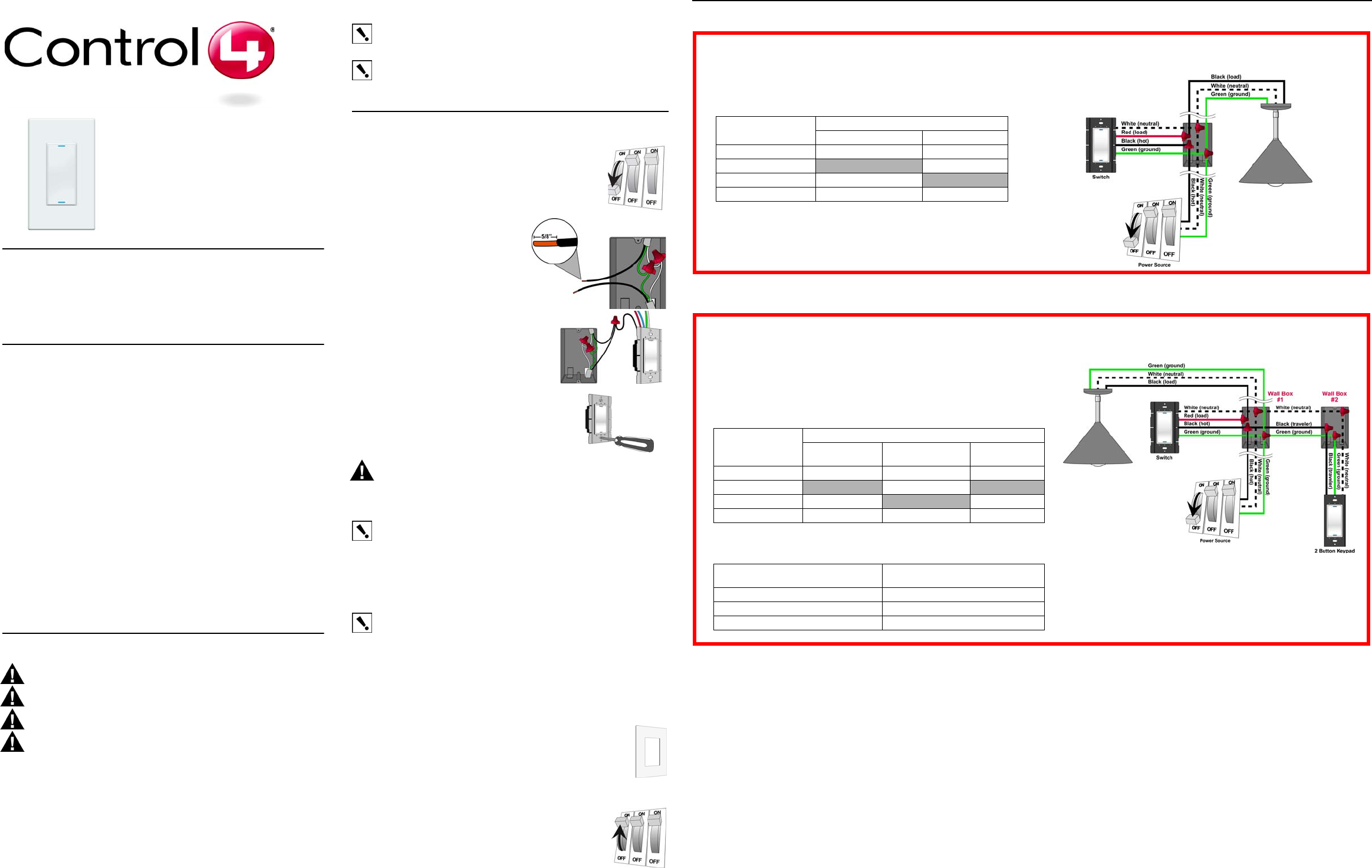
Single-Location Scenario—Power Source at Wall Box
NOTE: This device will not function without a neutral AC connection.
To wire the switch for a Control4 single-location scenario in which the
power is first routed to the wallbox, connect together and cap with a
wire nut the wires indicated in the following table:
Switch Wires Wires in the Wall Box
From Power Source To Light Fixture
White (neutral) White (neutral) White (neutral)
Red (load) None black (load)
Black (hot) Black (hot) None
Green (ground) Green (ground) Green (ground)
Two-Location Scenario—Power Source at Wall Box
NOTE: This device will not function without a neutral AC connection.
To wire the switch and a multi-button keypad in a two-location scenario
(Control4’s 3-way-switch solution) where the power is first routed to the wall
box, do the following:
1. Wire the switch into Wall Box #1 by connecting together and capping with a
wire nut the following wires:
Switch Wires Wires in Wall Box 1
From Power
Source To Light Fixture To Wall Box 2
White (neutral) White (neutral) White (neutral) White (neutral)
Red (load) None Black (load) None
Black (hot) Black (hot) None Black (traveler)
Green (ground) Green (ground) Green (ground) Green (ground)
2. Wire the multi-button keypad into Wall Box #2 by connecting together and
capping with a wire nut the following wires:
Multi-Button Keypad Wires Wires in Wall Box 2
(from Wall Box 1)
White (neutral) White (neutral)
Green (ground) Green (ground)
Black (traveler) Black (traveler)
Optional Antenna Extension
In some installation scenarios, it may be desirable to enhance the Switch's wireless (RF)
transmission capabilities. This may be needed to overcome issues such as local
interference from other devices, range considerations due to the distance between devices
or the use of metallic faceplates. The Control4 Wireless Switch has been designed with a
wire whip antenna coiled underneath the plastic button that can be extended to
accommodate such scenarios. Instructions for extending the antenna are provided below.
WARNING! To avoid risk of electrical shock that may cause personal injury or
damage to the Switch, this procedure should be performed prior to connecting the
switch at the wall box.
CAUTION! Risk of Equipment Damage. This procedure enables advanced
functionality and should only be performed by a competent trained installer.
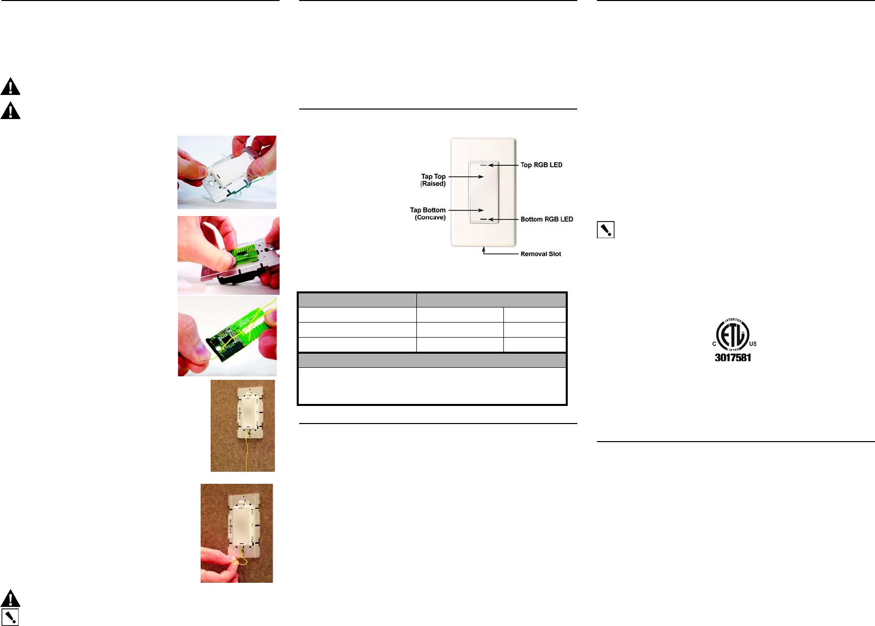
1 Remove the plastic button frame by squeezing
the side tabs near the top and bottom of the
button and pulling outward. A small flat-head
screw driver can also be used to assist in
releasing the tabs.
2 Once the button has been removed, detach the
radio board from its connector by gently pulling
away from the switch frame.
3 Slip the end of the antenna out of the radio
board hole and uncoil it, being careful not to
exert undue tension on the wire. Once uncoiled,
thread the antenna wire under the plastic spacer
at the bottom of the radio board.
4 Re-attach the radio card to the switch frame by
carefully aligning the connector and pressing gently. Then
re-attach the button and button frame by aligning the
button frame securement tabs with the appropriate slots on
the switch frame and pushing gently. Ensure that the
antenna is routed through the small notch on the bottom
left-hand side of the button frame provided for this
purpose. Once the button has been re-attached, proceed
with the standard installation procedure for wiring the
switch to the light load and securing it into the wall box, as
described in Step 1 through Step 5 of “Installation
Instructions.”
5 The antenna has been designed to extend well beyond
the faceplate. For optimal performance, it should be
oriented in a vertical plane below the switch. To enable
this without leaving the antenna visible to the end user,
a very small hole should be made in the wall just below
the switch frame and the antenna inserted through the
hole back into the wall. Once the antenna has been
routed into the wall, proceed with standard installation
of the switch sub-plate and faceplate, as described in
Step 6 and Step 7 of “Installation Instructions.”
CAUTION! Risk of Equipment Damage. The
antenna must not be inserted into the junction box containing high voltage wires.
IMPORTANT! Do not shortened or cut the antenna in any way as this may
seriously impair transmission capabilities.
Troubleshooting
If light does not turn on:
•Ensure at least one LED on the face of the switch is lit.
•Ensure the light bulb is not burned out and is screwed in tightly.
•Ensure circuit breaker is not turned OFF or tripped.
•Check for proper wiring (see the “”section).
•For help on the installation or operation of this product, email or call the Control4
Technical Support Center. Please provide your exact model number. Contact
support@control4.com or see the web site www.control4.com.
Operation and Configuration
On initial power up, the unit
will flash the Red/Green/
Blue (RGB) LEDs, which
can be programmed with
different colors for different
states or color preferences.
To set up this switch for use
with a Control4 system,
refer to your system setup
documentation.
To operate this switch as a stand-alone device, refer to the following tables.
Limited 2 Year Warranty
Control4 Corporation ("Control4") warrants that at the time of first-consumer sale, this
product will be free from defects in material and manufacture. Control4 further warrants
that for a period of 2 years (24 months) after initial consumer sale, the product will function
in accordance with its specification, provided that it is installed and maintained under
normal and proper use. This warranty extends only to products purchased directly from
Control4 or an Authorized Control4 Reseller. If the product proves to be defective in
material or workmanship during the warranty period, it may be returned to the place of
purchase and Control4 will, at its sole option, repair or replace the product with a like
product. This warranty provides the consumer purchaser with specific legal rights, which
may vary per state or country. For complete warranty information, including details on
consumer legal rights as well as warranty exclusions, visit www.control4.com/warranty.
Regulatory Compliance
FCC
FCC ID: R33C4SW101Z
This device complies with Part 15 of the FCC Rules. Operation is subject to the following
two conditions: (1) this device may not cause harmful interference, and (2) this device
must accept any interference received, including interference that may cause undesired
operation.
This equipment has been tested and found to comply with the limits for a Class B digital
device, pursuant to Part 15 of the FCC Rules. These limits are designed to provide
reasonable protection against harmful interference in a residential installation. This
equipment generates, uses, and can radiate radio frequency energy and, if not installed
and used in accordance with the instructions, may cause harmful interference to radio
communications. However, there is no guarantee that interference will not occur in a
particular installation. If this equipment does cause harmful interference to radio or
television reception, which can be determined by turning the equipment off and on, the
user is encouraged to try to correct the interference by one or more of the following
measures:
•Reorient or relocate the receiving antenna.
•Increase the separation between the equipment and receiver.
•Connect the equipment into an outlet on a circuit different from that to which the
receiver is connected.
•Consult the dealer or an experienced radio/TV technician for help.
IMPORTANT! Any changes or modifications not expressly approved by the
party responsible for compliance could void the user’s authority to operate this
equipment.
ETL Statement
ETL Control Number: 3017581
This product has been tested by ETL and was found to comply with the Standard for Safety
for Industrial Control Equipment:
•UL/ANSI Standard 508 (Seventeenth Edition)
•CSA Standard C22.2 No. 14-05
Industry Canada
This Class B digital apparatus complies with Canada ICES-003.
Cet appareil numérique de la classe B est conforme à la norme NMB-003 du Canada.
About this Document
United States Patents Pending. Copyright © 2007 Control4 Corporation. Control4 and the
Control4 logo are registered trademarks of Control4 Corporation. All trademarks are
properties of their respective owners. Part Number: 200-00036 Rev A
Operate Switch Expected behavior of RGB LEDs:
To operate switch: Top Bottom
Turn ON: Tap top. Lit, full brightness Not lit
Turn OFF: Tap bottom. Not lit Lit, full brightness
Care and Cleaning
Do NOT paint switch or its wall plate.
Do NOT use any chemical cleaners to clean the switch.
Clean surface with a soft damp cloth as needed.
Sample Wiring Configurations
Wireless Fireplace
Switch Installation
Guide
Supported Models
C4-FS101-Z-W Wireless Fireplace Switch (White)
C4-FS101-Z-B Wireless Fireplace Switch (Black)
C4-FS101-Z-A Wireless Fireplace Switch (Almond)
This device requires a neutral AC connection.
Specifications and Supported Fixtures
This Control4® Wireless Fireplace Switch operates independently or as part of a
Control4® home automation system to enable intelligent lighting control. It installs in a
standard wall box using typical wiring standards and communicates with other devices
through a wireless RF (radio frequency) connection.
IMPORTANT! Use or modification of this product in a manner not expressly
approved by Control4 voids your warranty. Further, Control4 is NOT liable for
any damage incurred with the misuse of this product. See "Limited 2 Year
Warranty."
IMPORTANT! The range and performance of the wireless control system is
highly dependent on the following: (1) distance between devices; (2) layout of
the home; (3) walls separating devices; and (4) electrical equipment located
near devices.
Installation Instructions
1 TURN OFF POWER by switching off the circuit breaker or
removing the fuse and test that power is off before wiring!
2 Identify your wiring application (refer to the appropriate diagram
in “” on the back page).
• "Single-Pole (with power source at wall box) - see Figure 1
• "3-Way (with power source at wall box) - see Figure 2
3 Prepare wires by removing pre-cut
insulation from the appropriate fireplace
switch leads. Wire insulation should be
stripped back 5/8 of an inch from the wire
end (as shown).
4 Connect the fireplace switch wires to the
wall box wires using wire nuts according to the
relevant wiring diagram. See “Sample Wiring
Configurations.”
5 Mount fireplace switch into wall box by partially
securing the wall box screws attached to the fireplace
switch. Ensure that the word "Top" on the fireplace
switch frame is facing up. Bend wires in a zigzag
pattern so that they easily fold into the wall box.
WARNING! Ground the Wireless Fireplace Switch
in accordance with the National Electric Code (NEC) requirements. Although
the fireplace switch's aluminum yoke plate and green ground wire are directly
bonded together inside the fireplace switch, DO NOT rely solely upon the yoke
plate's contact with a metal wall box for adequate grounding. Use the fireplace
switch's ground wire to make a secure connection to the safety ground of the
electrical system.
IMPORTANT! Not grounding this product according to the preceding may
result in an installation less immune to damage caused by electrical
disturbances, such as lightning, and void the warranty.
6 If you are using the Control4 push-on (screw-less) wall plate that shipped with
your fireplace switch:
a. For a single-gang scenario, attach the black plastic sub-plate using the
provided sub-plate screws.
IMPORTANT! Tighten the screws until the back side of the metal yoke plate
is even with the wall surface, but no farther. Over-tightening can damage the
fireplace switch and cause mechanical malfunction. Do NOT use a power
screw driver to install this device as this may lead to over-tightening.
b. If you are installing in a multi-gang scenario, only partially tighten the
mounting screws, leaving about 1/8 of an inch gap between the wall and the
yoke plates prior to attaching the black plastic sub-plate. This allows each
device in a multi-gang scenario to conform to the sub-plate, creating a single
assembly. Secure the multi-gang sub-plate to all devices using the provided
sub-plate screws. Then secure the assembly by tightening the wall box
screws the remaining 1/8 of an inch. Do not over-tighten any of the screws
or you will misalign the flat plane of the multi-gang wall plate.
c. With the wall plate's removal slot facing down, push the wall
plate onto the fireplace switch's black plastic sub-plate.
7 If you are using a Decora-style screw-on wall plate:
a. Do not attach the fireplace switch's black plastic sub-plate
b. Align the fireplace switch to the wall box and fasten with screws.
c. Fasten the wall plate to the fireplace switch with screws.
8 Turn ON power at the circuit breaker or replace fuse from fuse
box.
9 Test the fireplace switch to see if it is working properly. See
"Operation and Configuration" for specific instructions.
Power: 120 VAC +/-10% 50/60 Hz
300 mW when off
850 mW when on
Supported Load
Types and Ratings:
30 VDC 8.3A
Operating
Temperature:
All load ratings are based on an ambient temperature of
25 degrees Celsius.
Volume: 5.0 Cubic inches
Communications: ZigBee, IEEE 802.15.4, 2.4 GHz, 15-channel, spread
spectrum radio
Warnings & Considerations
WARNING! Install in accordance with all national and local electrical codes.
WARNING! Improper use or installation can cause SERIOUS INJURY,
DEATH or LOSS/DAMAGE OF PROPERTY.
WARNING! If you are unsure about any part of these instructions, consult a
qualified electrician.
WARNING! Use this device only with copper or copper clad wire. This product
has NOT been approved for use with Aluminum wiring.
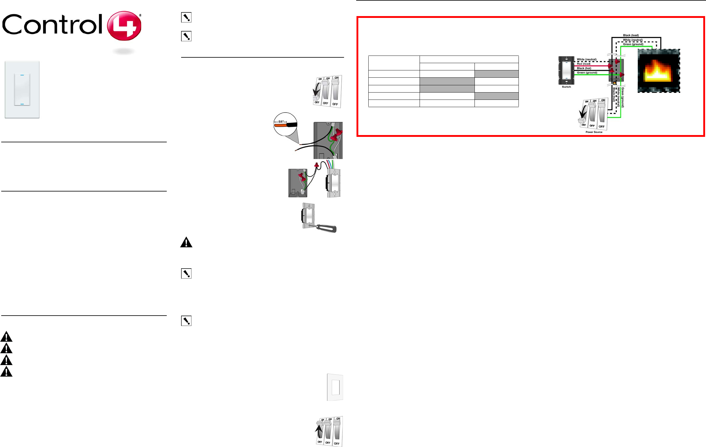
Single-Location Scenario—Power Source at Wall Box
NOTE: This device will not function without a neutral AC connection.
To wire the switch for a Control4 single-location scenario in which the
power is first routed to the wallbox, connect together and cap with a
wire nut the wires indicated in the following table:
Fireplace Switch
Wires Wires in the Wall Box
From Power Source To Fireplace
White (neutral) White (neutral) None
Orange (load) None White (load)
Orange (load) None Black (load)
Black (hot) Black (hot) None
Green (ground) Green (ground) Green (ground)
Placeholder Image
Optional Antenna Extension
In some installation scenarios, it may be desirable to enhance the Fireplace Switch's
wireless (RF) transmission capabilities. This may be needed to overcome issues such as
local interference from other devices, range considerations due to the distance between
devices or the use of metallic faceplates. The Control4 Wireless Fireplace Switch has
been designed with a wire whip antenna coiled underneath the plastic button that can be
extended to accommodate such scenarios. Instructions for extending the antenna are
provided below.
WARNING! To avoid risk of electrical shock that may cause personal injury or
damage to the Fireplace Switch, this procedure should be performed prior to
connecting the fireplace switch at the wall box.
CAUTION! Risk of Equipment Damage. This procedure enables advanced
functionality and should only be performed by a competent trained installer.
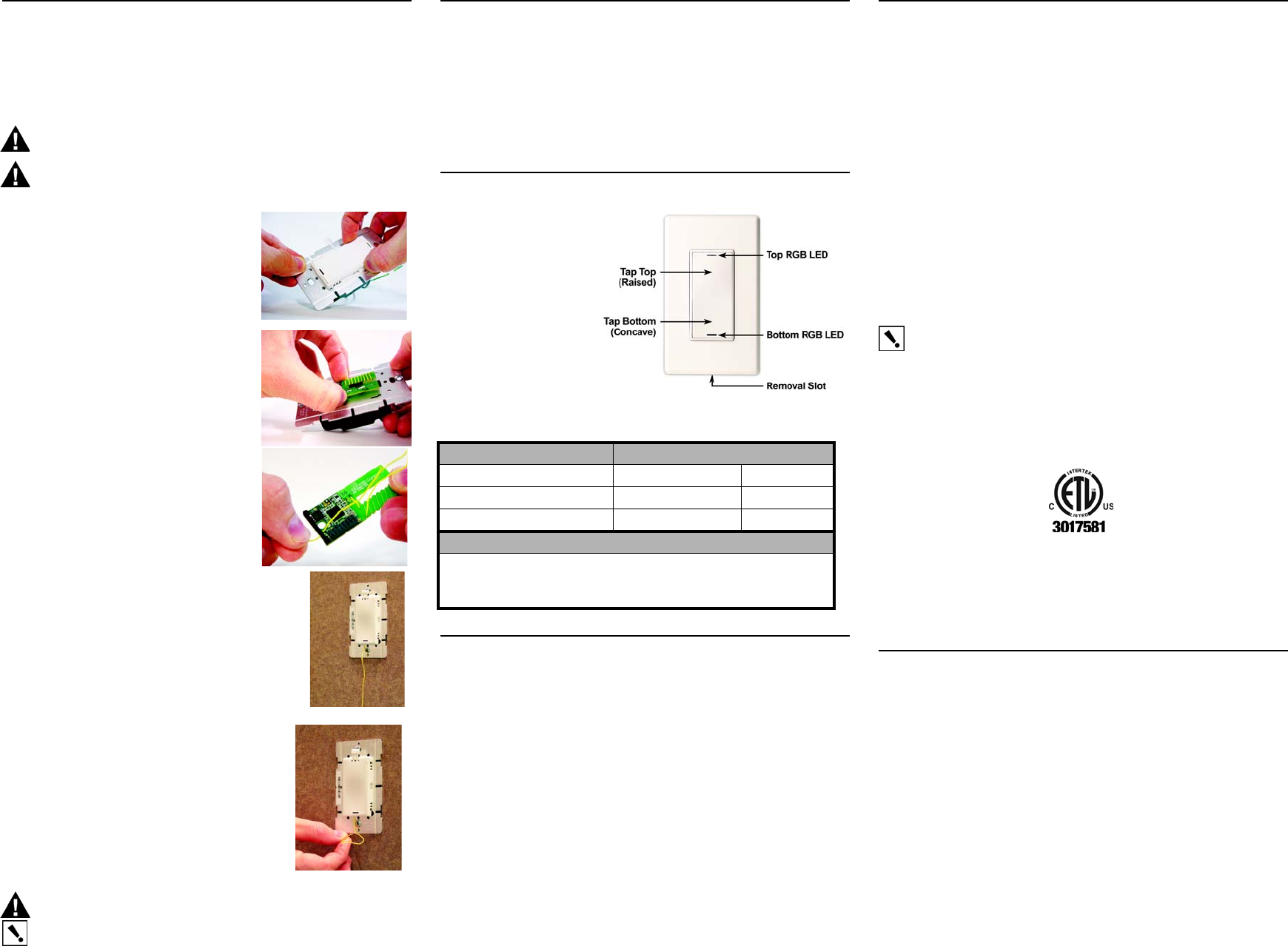
1 Remove the plastic button frame by squeezing
the side tabs near the top and bottom of the
button and pulling outward. A small flat-head
screw driver can also be used to assist in
releasing the tabs.
2 Once the button has been removed, detach the
radio board from its connector by gently pulling
away from the fireplace switch frame.
3 Slip the end of the antenna out of the radio
board hole and uncoil it, being careful not to
exert undue tension on the wire. Once uncoiled,
thread the antenna wire under the plastic spacer
at the bottom of the radio board.
4 Re-attach the radio card to the fireplace switch
frame by carefully aligning the connector and pressing
gently. Then re-attach the button and button frame by
aligning the button frame securement tabs with the
appropriate slots on the fireplace switch frame and
pushing gently. Ensure that the antenna is routed through
the small notch on the bottom left-hand side of the button
frame provided for this purpose. Once the button has been
re-attached, proceed with the standard installation
procedure for wiring the fireplace switch to the light load
and securing it into the wall box, as described in Step 1
through Step 5 of “Installation Instructions.”
5 The antenna has been designed to extend well beyond
the faceplate. For optimal performance, it should be
oriented in a vertical plane below the fireplace switch.
To enable this without leaving the antenna visible to the
end user, a very small hole should be made in the wall
just below the fireplace switch frame and the antenna
inserted through the hole back into the wall. Once the
antenna has been routed into the wall, proceed with
standard installation of the fireplace switch sub-plate
and faceplate, as described in Step 6 and Step 7 of
“Installation Instructions.”
CAUTION! Risk of Equipment Damage. The antenna must not be inserted into
the junction box containing high voltage wires.
IMPORTANT! Do not shortened or cut the antenna in any way as this may
seriously impair transmission capabilities.
Troubleshooting
If fireplace does not turn on:
•Ensure at least one LED on the face of the switch is lit.
•Ensure the pilot light is on or fireplace is in mode ready to be turned on (refer to
the fireplace documentation).
•Ensure circuit breaker is not turned OFF or tripped.
•Check for proper wiring (see the “”section).
•For help on the installation or operation of this product, email or call the Control4
Technical Support Center. Please provide your exact model number. Contact
support@control4.com or see the web site www.control4.com.
Operation and Configuration
On initial power up, the unit
will flash the Red/Green/
Blue (RGB) LEDs, which
can be programmed with
different colors for different
states or color preferences.
To set up this switch for use
with a Control4 system,
refer to your system setup
documentation.
To operate this switch as a stand-alone device, refer to the following tables.
Limited 2 Year Warranty
Control4 Corporation ("Control4") warrants that at the time of first-consumer sale, this
product will be free from defects in material and manufacture. Control4 further warrants
that for a period of 2 years (24 months) after initial consumer sale, the product will function
in accordance with its specification, provided that it is installed and maintained under
normal and proper use. This warranty extends only to products purchased directly from
Control4 or an Authorized Control4 Reseller. If the product proves to be defective in
material or workmanship during the warranty period, it may be returned to the place of
purchase and Control4 will, at its sole option, repair or replace the product with a like
product. This warranty provides the consumer purchaser with specific legal rights, which
may vary per state or country. For complete warranty information, including details on
consumer legal rights as well as warranty exclusions, visit www.control4.com/warranty.
Regulatory Compliance
FCC
FCC ID: R33C4SW101Z
This device complies with Part 15 of the FCC Rules. Operation is subject to the following
two conditions: (1) this device may not cause harmful interference, and (2) this device
must accept any interference received, including interference that may cause undesired
operation.
This equipment has been tested and found to comply with the limits for a Class B digital
device, pursuant to Part 15 of the FCC Rules. These limits are designed to provide
reasonable protection against harmful interference in a residential installation. This
equipment generates, uses, and can radiate radio frequency energy and, if not installed
and used in accordance with the instructions, may cause harmful interference to radio
communications. However, there is no guarantee that interference will not occur in a
particular installation. If this equipment does cause harmful interference to radio or
television reception, which can be determined by turning the equipment off and on, the
user is encouraged to try to correct the interference by one or more of the following
measures:
•Reorient or relocate the receiving antenna.
•Increase the separation between the equipment and receiver.
•Connect the equipment into an outlet on a circuit different from that to which the
receiver is connected.
•Consult the dealer or an experienced radio/TV technician for help.
IMPORTANT! Any changes or modifications not expressly approved by the
party responsible for compliance could void the user’s authority to operate this
equipment.
ETL Statement
ETL Control Number: 3017581
This product has been tested by ETL and was found to comply with the Standard for Safety
for Industrial Control Equipment:
•UL/ANSI Standard 508 (Seventeenth Edition)
•CSA Standard C22.2 No. 14-05
Industry Canada
This Class B digital apparatus complies with Canada ICES-003.
Cet appareil numérique de la classe B est conforme à la norme NMB-003 du Canada.
About this Document
United States Patents Pending. Copyright © 2007 Control4 Corporation. Control4 and the
Control4 logo are registered trademarks of Control4 Corporation. All trademarks are
properties of their respective owners. Part Number: 200-00048 Rev A (Draft 2)
Operate Fireplace Switch Expected behavior of RGB LEDs:
To operate switch: Top Bottom
Turn ON: Tap top. Lit, full brightness Not lit
Turn OFF: Tap bottom. Not lit Lit, full brightness
Care and Cleaning
Do NOT paint switch or its wall plate.
Do NOT use any chemical cleaners to clean the switch.
Clean surface with a soft damp cloth as needed.