User manual
™
™
Thermostat with Humidity
or Ventilation Control
User Guide
ii
Disclaimer
Control4® makes no representations or warranties with respect to any Control4 hardware, software, or the contents or use of this
publication, and specifically disclaims any express or implied warranties of merchantability or fitness for any particular purpose.
Control4 reserves the right to make changes to any and all parts of Control4 hardware, software, and this publication at any time,
without any obligation to notify any person or entity of such changes.
Trademarks
©2014 Control4. All rights reserved. All rights reserved. Control4, the Control4 logo, the Control4 iQ logo and the Control4
certified logo are registered trademarks or trademarks of Control4 Corporation in the United States and/or other countries. All
other names and brands may be claimed as the property of their respective owners. Pricing and specifications are subject to
change without notice.
Warranty
Control4 Corporation
11734 S. Election Road, Suite 200
Salt Lake City, UT 84020 USA
http://www.control4.com
Thermostat with Humidity or Ventilation Control User Guide
Part Number: 90-1883 Rev A, 3/26/2014
Model Number: C4-THERM-WH
For complete warranty information, including details on consumer legal rights as well as warranty exclusions, visit
www.control4.com/warranty, or refer to the Thermostat with Humidity or Ventilation Control User Guide on the Control4 website,
Resources > Documentation page at http://www.control4.com/residential/products/resources/.

iii
Contents
About your new thermostat ................................................1
Supported model ........................................................1
Important safety instructions ..............................................1
Thermostat features ......................................................1
Quick reference to controls and display ....................................1
Operation ...............................................................2
Select system mode (Em Heat/Heat /O/Cool /Auto) ...................... 2
Change temperature set point ............................................ 2
Select fan setting (On/Auto/Circ) ........................................ 2
Maintenance reminders .................................................. 2
Screen lockout .......................................................... 2
Power and battery replacement .......................................... 3
Indoor Air Quality functions ...............................................3
Event-Based™ air cleaning ................................................ 3
Humidifier control ....................................................... 3
Automatic mode .................................................. 3
Manual mode ......................................................4
Dehumidifier control ..................................................... 4
If dehumidification is installed .......................................4
If dehumidification is done with the air conditioner ...................4
Fresh air ................................................................5
Program schedule and holds ...............................................5
Understanding program schedules ........................................ 5
Progressive recovery .................................................... 5
Program schedule holds
2 Hour ............................................................ 5
Permanent ........................................................ 5
Next Event ........................................................6
Timed ............................................................ 6
1
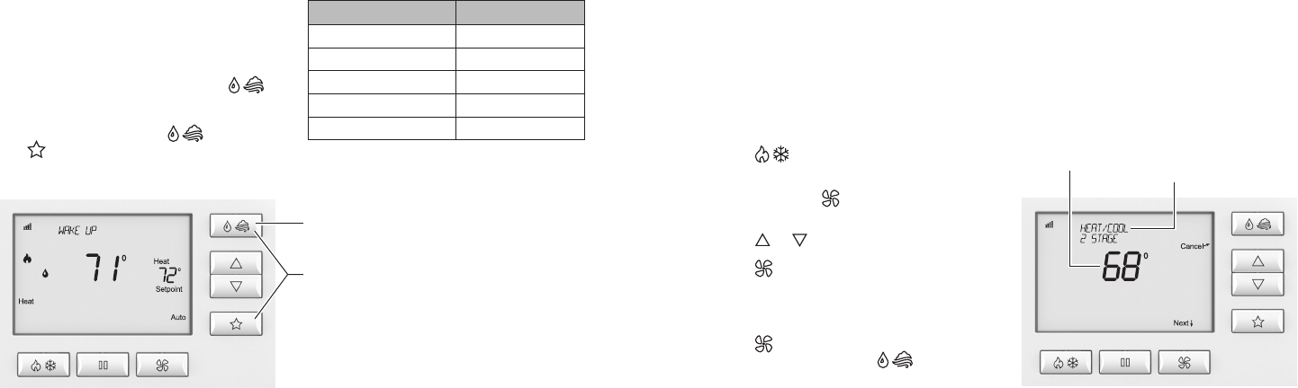
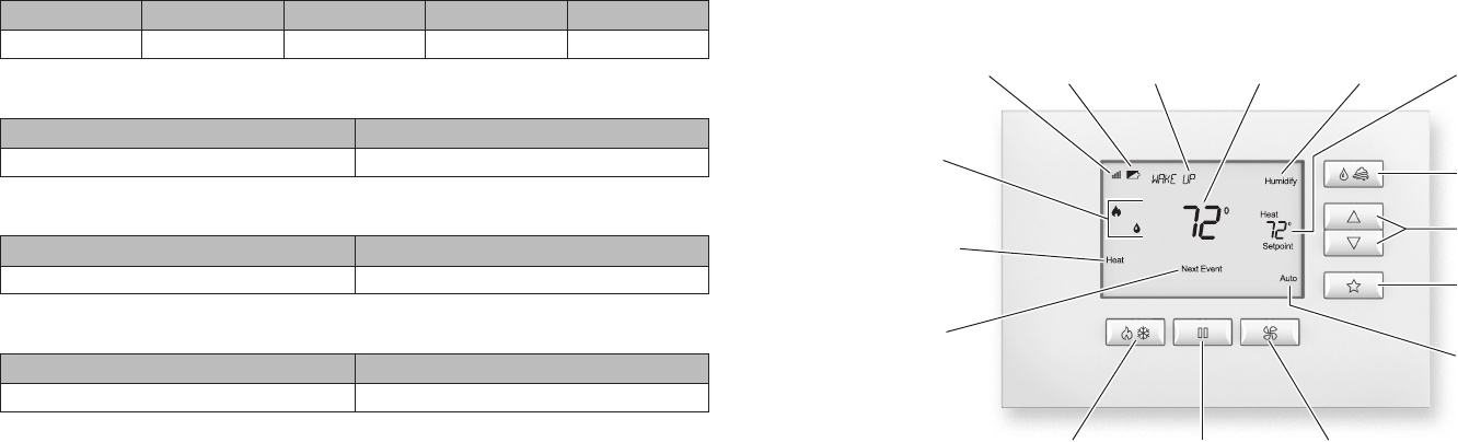
Quick reference to controls and display
Thermostat features
• Up to 4 stage heat and 2 stage cool operation.
• Indoor air quality control.
• Humidification (automatic or manual control).
• Dehumidification.
• Event-Based™ air cleaning.
• Ventilation with temperature and humidity limits.
• Temperature control.
• Message center provides feedback and instructions.
• Dual power option (24VAC or battery).
• Programmable fan control with fan circulation mode.
• Easy-to-use temperature control can override program
schedule at any time.
• Progressive recovery ensures proper temperature at the
start of a program event.
• Built-in compressor protection prevents damage to your
equipment.
• System test mode.
Control4 thermostat with humidity or ventilation control
User guide
Quick reference to controls and display
Home screen
Note: Backlight is activated with the first button press and automatically turns o.
Equipment status
System Mode setting
System Mode button Hold button Fan Mode button
Indoor Air Quality button
(optional)
Setpoint Adjust buttons
Temperature setting
Fan Mode setting
Presets button
Hold status
Radio signal
strength indicator
Low battery indicator Message center Indoor Air Quality settingCurrent indoor temperature
Supported model
C4-THERM-WH Thermostat—White
Important safety instructions
Warning! Install in accordance with all national and
local electrical codes.
Warning! This product is not intended for use with
line-voltage baseboard heaters.
Important: Improper use or installation can cause
loss/damage of property.
Important: Operate within the limits of this device as
specified in this Thermostat with Humidity or Ventilation
Control User Guide and Thermostat with Humidity or
Ventilation Control Safety and Installation Instructions.
Important: Using this product in a manner other than
outlined in this document voids your warranty. Further,
Control4 is not liable for any damage incurred with the
misuse of this product. See the warranty information
in the Thermostat with Humidity or Ventilation Control
User Guide or on the Control4 website at
www.control4.com/warranty.
2
Operation
Operation
Select system mode
(Em Heat/Heat/O/Cool/Auto)
Press button to select:
Em Heat: (only for heat pumps with auxiliary heat) Thermostat
controls auxiliary heat. Heat pump will not operate in Em Heat
mode.
Heat: Thermostat controls only the heating system.
O: Heating and cooling systems are o.
Cool: Thermostat controls only the cooling system.
Auto: (if enabled in installer setup) Thermostat automatically
selects heating or cooling depending on the indoor temperature.
The current system mode selection will flash. After 7 seconds
without any button presses, the selected system mode will be
accepted by the thermostat.
Change temperature set point
Press or buttons to adjust the current set point.
Select fan setting (On/Auto/Circ)
When the fan mode is changed during a program event it
remains in that mode until the next event starts. The fan must
be programmed to FAN ON in the schedule to run continuously
through all events.
Press button to select:
On: Fan runs continuously. Use this mode for maximum air
circulation/filtering.
Auto: Fan runs only when the heating or cooling system is on.
Circ: Same as Auto, but ensures the fan is on for at least 30
minutes per hour. Use this mode for a balance of energy savings
and air circulation/cleaning.
The current fan selection will flash. After 7 seconds without any
button presses, the selected fan mode will be accepted by the
thermostat.
Maintenance reminders
Maintenance reminders are set up by the installer to indicate
when the equipment is due for service. If a maintenance reminder
is displayed, call your HVAC dealer for service. They can be
cleared by setting the system mode to o and then holding the
button continuously for 5 seconds. Press and select Yes
to Service Reminders and then press button (Next). Press
and buttons to select Yes for each reminder you would like
to reset. Press button (Next) to go to the next reminder or
button (Back) to go to a previous reminder. Press button
(Done) to reset the selected service reminders.
Screen lockout
Certain features of the thermostat can be locked so that changes
at the thermostat are not allowed. This feature can be overridden
by pressing and holding button for 5 seconds.
3
Indoor Air Quality functions
Power and battery replacement
This thermostat can be AC powered, battery powered, or both
(to provide backup power for communication with the Control4
system). The thermostat uses four alkaline AA batteries.
The thermostat has a memory backup that saves the thermostat
settings in case of a power interruption. The system settings will
be retained, but the clock resets after both battery and AC power
are removed. Clock synchronization comes from the connection
to the Control4 system. To access the batteries for replacement,
remove the bezel as shown.
Automatic or manual mode is configured by the installer. To
determine which mode the thermostat is set to, see the diagrams
on pages 3 and 4.
In automatic mode you will receive the optimum amount of
humidity so that your home and its furnishings are protected
from the damaging eects of excess condensation or low
humidity during heating season. The thermostat automatically
adjusts your home’s relative humidity based on the outdoor
temperature.
The humidity setting needs to be set initially to meet your
home’s conditions. Follow these steps when adjusting your
thermostat.
1 Adjust the humidity setting to “3” which is within normal
range. During the next 24-48 hours it may be necessary to
adjust the setting for more or less humidity, depending on
your personal comfort and home’s requirements.
2 During the coldest portion of the first heating season, minor
adjustments may be necessary. This is dependent upon your
home’s construction.
The relative humidity in your home will now be accurately
controlled to meet your needs and should not need further
adjustment during future heating seasons.
Humidifier Control screen for humidification in automatic mode
Humidifier control
If humidification is installed it can be controlled in two modes,
automatic or manual.
Press button to select Humidify and enter the Humidifier
Control screen.
Indoor Air Quality functions
Event-Based™ air cleaning
If installed, air cleaning can be controlled through the Control4
system. Air cleaning will activate the fan for the purpose of air
cleaning and can operate in five dierent modes as defined on
this page.
O: The air cleaner will not call the fan for the purpose of air
cleaning.
Note: If air cleaning is installed, air cleaning will still
occur during normal fan operation during heating,
cooling or other indoor air quality events.
Constant Clean: This option will provide the maximum amount of
air cleaning available. The air cleaner will be active for 24 hours a
day, seven days a week.
Automatic: The air cleaner will run a minimum of 30 minutes
every hour. The air cleaner will monitor the amount of time your
heating and cooling system runs; if 30 minutes is not reached
the air cleaner will automatically turn on. This will maximize the
amount of air cleaning while minimizing energy consumption.
Event Clean (3 hour cycle): When selected, the air cleaner
will run for 3 hours continuously and then return to the most
recent mode of O, Automatic, or Constant Clean. This option
only cleans the air when needed; an example would be after
vacuuming.
Allergies (24 hour cycle): When seasonal allergies spike and
outside air quality is at its worst, choose this option. Your air
cleaner will run continuously for 24 hours, then return to the most
recent mode of O, Automatic, or Constant Clean.
Note: The thermostat will manage fan and air cleaning
selections when the selections overlap.
Humidification
setpoint
Humidifier
adjustment
Automatic mode:
indication of
humidification
setpoint level
Done button
(exit Humidifier
Control)
4
Indoor Air Quality functions
Humidification
setpoint
Dehumidification
setpoint
Humidifier
adjustment
Dehumidifier
adjustment
Done button
(exit Humidifier
Control)
Done button
(exit Dehumidifier
Control)
In manual mode it is important to anticipate a drop in outdoor
temperature and reduce the setting accordingly to avoid
excessive condensation. Use the following table to determine the
proper relative humidity setting.
Outdoor temperature/indoor relative humidity
Outside temperature Recommended relative humidity
+50°F 50%
+40°F 45%
+30°F 40%
+20°F 35%
+10°F 30%
0°F 25%
-10°F 20%
-20°F 15%
Humidifier Control screen for humidification in manual mode
Dehumidifier control
If dehumidification is installed the thermostat can be configured,
through the installer set-up, to control dehumidification with
either a whole home dehumidifier or with the air conditioner
(cooling unit).
Press button to select Dehumidify and enter the
Dehumidifier Control screen.
Manual mode:
screen cycles
recommended
humidification
setpoints for
various outdoor
temperatures
The thermostat will allow you to set the desired humidity (%
relative humidity) level in your home and can be used to turn the
dehumidification On or O.
Use the dehumidification adjustment to set the dehumidification
setpoint to 60% when first installed. Allow dehumidification to
run until the initial setpoint is reached, before deciding if you
want to change the humidity setting.
Raise the setting if you prefer the air to be less dry; this will
reduce the amount of time that dehumidification runs.
Lower the setting if you prefer the air to be more dry; this will
increase the amount of time that dehumidification runs.
Your comfort is the best measure of how to adjust your setting.
When first installed, your dehumidifier has to remove all the
moisture that is initially in your home. The home acts like a
sponge so the moisture in the materials of your home is at the
same level as the air. After drying the air, the materials of the
home will release the moisture back into the air until they are
again at the same level. As a result, it is not uncommon for
dehumidification to operate for an extended period of time when
it is first installed.
Energy Saving Tip #1:
Adjust the setting to be as high as is comfortable to reduce
dehumidification run time – if it feels clammy or smells damp or
moldy lower the setting. To save energy, turn the dehumidifier
control OFF when you open your windows just as you would with
air conditioning.
Energy Saving Tip #2:
If vacating your home for an extended period in the summer, set
the relative humidity at 60% and set the cooling setpoint as high
as you are comfortable setting it to in cooling mode. Consult with
appropriate professionals regarding the highest temperature that
is safe for your pets or possessions. This will keep the humidity
at a controlled level to help prevent mold while minimizing the
amount of the cooling energy used.
Dehumidifier Control screen with only dehumidification installed
If dehumidification is done with the air conditioner, the
thermostat will cool up to 3°F beyond the cooling setpoint for
dehumidification. Note overcooling may not be sucient to meet
the dehumidification setpoint.
5
Program schedule and holds
Program schedule and holds
Understanding program schedules
Setting the schedule for the thermostat is done at the Control4
system.
Progressive recovery
The Progressive Recovery feature allows the thermostat to
activate the heating and cooling equipment prior to a scheduled
event in order to reach the desired temperature at the start of
that scheduled event.
Example: If the Next Event time is 6 a.m., and the temperature is
70°, the heat will come on before 6 a.m., so the temperature is
70° by 6 a.m.
Program schedule holds
Press button to initiate a Next Event, 2 Hour or Permanent
hold. All options will be displayed and the current hold selection
will flash.
After 7 seconds without any button presses the selected hold
will be accepted by the thermostat. After the option of 2 Hour
if button is pressed again, no hold options will be displayed.
This indicates no hold option is to be selected and can be used to
cancel any active holds. Pressing button again will display all
hold options with Next Event selected.
While in Next Event, 2 Hour, or Permanent hold, the temperature
setting and fan mode can be adjusted and will stay at that setting
until the hold ends or is cancelled.
Next Event hold will override the temperature setting and fan
mode for the current schedule event and will remain active until
the next schedule event occurs.
2 Hour hold will override the temperature setting and fan mode
for the schedule events and will remain active for two hours from
the time the hold is initiated.
Permanent hold will override the temperature settings for all
events.
O: Ventilation will not run.
Automatic: Ventilation will cycle based on the parameters set by
the installer to meet your home’s ventilation requirements.
3 Hour Event: Ventilation will be constantly energized for 3
hours and then the fresh air mode will return to O or Automatic
depending on which was mode was most recently active. This
option is used when fresh air is needed. An example would be
after cooking.
24 Hour Event: Ventilation will be constantly energized for 24
hours and then the fresh air mode will return to O or Automatic
depending on which was mode was most recently active. This
option is used when a large amount of fresh air is desired. An
example would be a day with desirable outdoor conditions.
Fresh Air screen
Fresh Air
If ventilation is installed, Fresh Air can operate in four dierent
modes as defined on this page.
Press button to select Fresh Air and enter the Fresh Air
screen.
Fresh Air mode
adjustment
Done button
(save mode and
exit Fresh Air)
Fresh Air mode
selection
6
Program schedule and holds
Next Event hold
Press or buttons to immediately adjust the temperature
when the schedule is running. This will hold the temperature
setting until the next scheduled event.
A Next Event hold can also be initiated by pressing button and
selecting Next Event.
Timed hold
Timed hold can be set at the Control4 System.

™
™
control4.com | 888.400.4070 90-1883 3.14

Thermostat with Humidity or
Ventilation Control
Safety and Installation Instructions

iiiii
Disclaimer
Control4® makes no representations or warranties with respect to any Control4 hardware, software, or
the contents or use of this publication, and specifically disclaims any express or implied warranties of
merchantability or fitness for any particular purpose. Control4 reserves the right to make changes to any
and all parts of Control4 hardware, software, and this publication at any time, without any obligation to
notify any person or entity of such changes.
Trademarks
©2014 Control4. All rights reserved. All rights reserved. Control4, the Control4 logo, the Control4 iQ logo
and the Control4 certified logo are registered trademarks or trademarks of Control4 Corporation in the
United States and/or other countries. All other names and brands may be claimed as the property of their
respective owners. Pricing and specifications are subject to change without notice.
Warranty
Control4 Corporation
11734 S. Election Road, Suite 200
Salt Lake City, UT 84020 USA
http://www.control4.com
Thermostat with Humidity or Ventilation Control Safety and Installation Instructions
Part Number: B2206227 Rev B, 2/15/2014
Model Number: C4-THERM-WH
For complete warranty information, including details on consumer legal rights as well as warranty
exclusions, visit www.control4.com/warranty, or refer to the Thermostat with Humidity or Ventilation
Control User Guide on the Control4 website, Resources > Documentation page at
http://www.control4.com/residential/products/resources/.
Contents
Supported model ..........................................................1
Important safety instructions ...............................................1
General description ....................................................... 2
Box contents .............................................................3
Supported systems .......................................................3
Installation ...............................................................4
Installation location recommendations ....................................4
If replacing an existing thermostat ........................................ 5
Thermostat mounting ...................................................6
Wiring terminal ......................................................... 7
Outdoor temperature sensor (included) ...................................9
Remote temperature sensor (optional) ....................................11
Wiring diagrams ........................................................13
Conventional heat/cool single transformer ...........................13
Conventional heat/cool two transformers ............................13
Heat pump single transformer ......................................14
Heat pump two transformers .......................................14
Indoor Air Quality equipment—dehumidifier. . . . . . . . . . . . . . . . . . . . . . . . . .15
Indoor Air Quality equipment—humidifier ............................15
Indoor Air Quality equipment—ventilation ............................16
Power and battery replacement ..........................................17

iv 1
Setup and testing ........................................................18
Equipment Type selection switch .........................................18
Installer Setup menu .....................................................19
Change system settings .................................................20
HVAC Installer system settings table ...................................21-25
Indoor Air Quality system settings tables .................................26
Air cleaning sytem settings table ...................................26
Humidifier system settings table ................................27-28
Dehumidifier system settings table .................................29
Ventilation system settings table ................................30-32
Climate map for ASHRAE Fresh Air Setup ................................33
Managing the ZigBee® network connection ...............................34
System Test menu ......................................................35
System Test tables ..................................................38-42
Quick reference to controls and display ....................................43
Troubleshooting .........................................................44
Error codes .............................................................47
Thermostat features .....................................................48
Specifications ...........................................................49
Supported model
Supported model
C4-THERM-WH Thermostat—White
Important safety instructions
Warning! Install in accordance with all national and local electrical codes.
Warning! This product is not intended for use with line-voltage
baseboard heaters.
Important: Improper use or installation can cause loss/damage of
property.
Important: Operate within the limits of this device as specified in this
Thermostat with Humidity or Ventilation Control Safety and Installation
Instructions and Thermostat with Humidity or Ventilation Control User
Guide.
Important: Using this product in a manner other than outlined in this
document voids your warranty. Further, Control4 is not liable for any
damage incurred with the misuse of this product. See the warranty
information in the Thermostat with Humidity or Ventilation Control User
Guide or on the Control4 website at
www.control4.com/warranty.
2 3
General description
General description
This Control4® Thermostat enables intelligent HVAC and Indoor Air Quality
control as part of a Control4 automated system. This thermostat uses the ZigBee®
(802.15.4) wireless networking standard to communicate with the Control4 system.
The Control4 Thermostat features a backlit LCD that displays the temperature,
HVAC status, Indoor Air Quality control status, fan status, hold status, and HVAC
operating mode. The home screen allows temperature setpoint adjustments,
HVAC mode change, various hold options, fan control, and access to the Indoor
Air Quality control screens. The Indoor Air Quality control screens can be used to
control ventilation, humidification, or dehumidification. The thermostat can operate
as a stand-alone control if it loses communication with the Control4 system.
Box contents
• Thermostat
• Wired outdoor temperature sensor
• 4 AA batteries
• 2 screws
• 2 wall anchors
• Warranty card
• Control4 Thermostat with
Humidity or Ventilation Control
Safety and Installation Instructions
(this document)
Supported systems
• One or two stage conventional
heat/cool system
• One or two stage heat pump with
up to two stages of auxiliary or
emergency heat
• Optional heat only or cool only
operation
• Configurable for electric or fossil
fuel heating
• Millivolt heat
• Hydronic heat
Box contents
4 5
Installation
Installation
Installation location recommendations
Thermostat should be mounted:
• On an interior wall, in a frequently occupied space.
• Approximately 5' (about 1.5 meters) above the floor.
• At least 18" (about 0.5 meter) from an outside wall.
• Thermostat can be mounted to a vertical, single gang, electrical junction box.
Do not mount thermostat:
• Behind doors, in corners, or other dead air spaces.
• In direct sunlight, near lighting fixtures, or other appliances that give o heat.
• On an outside or unconditioned area wall.
• In the flow of a supply register, in stairwells, or near outside doors.
• On a wall with concealed pipes or ductwork.
If replacing an existing thermostat
• If your existing thermostat is configured using system settings, record the
existing system settings so they can be referenced when setting the HVAC
Installer system settings for this thermostat. For detailed instructions on how
to access and read the system settings for your existing thermostat, refer to
the installation instructions for that thermostat.
• Turn o power to the thermostat.
• Remove the thermostat from the wall, but do not disconnect the wires yet.
• Check the number of wires attached to the existing thermostat. Wrap the bare
ends of any unused wires in electrical tape to prevent them from shorting to
other wires.
• If the existing thermostat has a letter identifying each wire, use a piece of tape
to label each wire with the corresponding letter. The labels can be used to
later identify the wires for your new thermostat.
• Disconnect the wires from the existing thermostat, taking care that none of
the wires fall back into the wall.
6 7
Installation
Thermostat mounting
1 Remove the rear mounting plate
from the thermostat.
2 Pull wires through the opening
on the back of the thermostat.
3 Position and level the mounting
plate of the thermostat on
the wall, and mark the hole
locations with a pencil.
4 Drill 1/4" (6.35 mm) holes and
insert the supplied anchors
(drywall only).
5 Place the mounting plate over
the anchors, then insert and
tighten the screws.
6 Seal the wire entry holes
to prevent drafts aecting
temperature readings.
Wiring terminal
Wire specifications:
18-24 gauge thermostat wire
Installation notes:
• Ensure that power at the
HVAC equipment is o.
• Loosen screw terminals,
insert stripped wire, and
re-tighten.
• Push the excess wire back
into the opening and
plug the wall opening to
prevent drafts.
Y2I1 W2
S2S1 T1 T2 I2
G
YO/B W
RC RL
C
G
YO/B W
RC RL
C
Y2I1 W2
S2S1 T1 T2 I2
8 9
Installation
I1 & I2—Indoor Air Quality control output
C—Common (optional when powered by batteries)
O/B—Reversing valve
Y—First-stage cooling / compressor
Y2—Second-stage cooling / compressor
G—Fan
RC—24VAC supply cooling1
R—24VAC supply heating1
W2—Second-stage heat / auxiliary
W—First-stage heat / auxiliary
L—System fault indicator (optional) (heat pump only)
S1 & S2—Outdoor temperature sensor (included)
T1 & T2—Remote temperature sensor (optional)
1 Jumper between RC & R is used in single-transformer systems (see wiring diagrams).
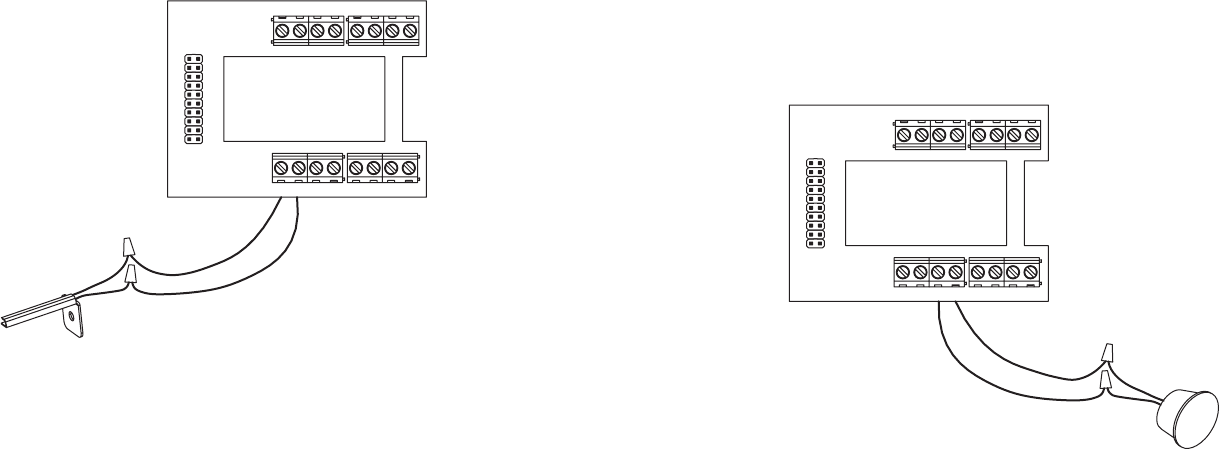
Outdoor temperature sensor (included)
Outdoor temperature can be measured by attaching the included sensor to the
S1 and S2 terminals. The outdoor sensor must be enabled in the thermostat’s
Installer Setup menu.
Heat pump models can use the outdoor temperature to eectively utilize the
heat pump:
• When the outdoor temperature is less than the Low Balance Point, the heat
pump is locked out and only auxiliary heating is used.
• When the outdoor temperature is higher than the High Balance Point, the
auxiliary heating is locked out and only the heat pump is used to provide
heating.
Indoor Air Quality functions can use the outdoor temperature sensor to:
• Control humidification setpoint based on outdoor temperature to prevent
condensation.
• Lock out humidification for temperatures over 60°F (15.6°C) or below -30°F
(-34.4°C).
• Lock out ventilation based on high and/or low outdoor temperatures.
10 11
Installation
Y2I1 W2
S2S1 T1 T2 I2
G
YO/B W
RC RL
C
G
Y
O/B
W
RC
RL
C
Y2I1 W2
S2S1 T1 T2 I2
The outdoor temperature sensor should
be mounted:
• On the side of the building out of direct
sunlight (north side recommended).
• Above snow line.
• At least 3' (about 1 meter) away from
exhaust vents and condensing lines.
• Using less than 300' (about 100 meters)
of wire.
• Do not route wires parallel to
120VAC lines.
A remote temperature sensor can be used if the thermostat is going to be
mounted in a concealed location. Additionally, Control4 programming can
be utilized to switch between the on-board temperature sensor and the
remote temperature sensor, allowing the temperature reading to come from
dierent areas based on time of day or daily activity. A AC-FMTS1-W flush
mount or AC-DOTS1-W
surface mount remote
temperature sensor
can be attached to the
T1 and T2 terminals
and mounted in a
recommended area.
The remote sensor
must be enabled in the
thermostat’s Installer
Setup menu. When
the remote sensor is
selected as the primary
sensor (System Setting
14 [Primary Sensor]), it
overrides the internal
sensor.
Y2I1 W2
S2S1 T1 T2 I2
G
YO/B W
RC RL
C
G
YO/B W
RC RL
C
Y2I1 W2
S2S1 T1 T2 I2
Remote temperature sensor (optional)
12 13
Installation
The remote temperature sensor should be mounted:
• On an interior wall, in a frequently occupied space.
• About 5' (1.5 meters) above the floor.
• At least 18" (about 0.5 meter) from an outside wall.
• Using less than 300' (about 100 meters) of wire.
Do not mount the remote sensor:
• Behind doors, in corners, or other dead air spaces.
• In direct sunlight, near lighting fixtures, or near other appliances that give o heat.
• On an outside or unconditioned area wall.
• In the flow of a supply register, in stairwells, or near outside doors.
• On a wall with concealed pipes or ductwork.
• Parallel to 120VAC lines.
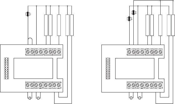
Conventional heat/cool wiring diagrams
Single transformer (use jumper wire) Two transformers (remove jumper wire)
Y2I1 W2
S2S1 T1 T2 I2
G
YO/B W
RC RL
C
G
YO/B W
RC RL
C
Y2I1 W2
S2S1 T1 T2 I2
JUMPER
OUTDOOR TEMP
SENSOR
(OPTIONAL)
REMO
TE TEMP
SENSOR
(OPTIONAL)
TRANSFORMER
1st HEATING
FAN
2nd COOLING
1st COOLING
2nd HEATING
Y2I1 W2
S2S1 T1 T2 I2
G
YO/B W
RC RL
C
G
YO/B W
RC RL
C
Y2I1 W2
S2S1 T1 T2 I2
OUTDOOR TEMP
SENSOR
(OPTIONAL)
REMO
TE TEMP
SENSOR
(OPTIONAL)
TRANSFORMERS
1st HEATING
FAN
2nd COOLING
1st COOLING
2nd HEATING
14 15
Installation
Heat pump wiring diagrams
Single transformer (use jumper wire) Two transformers (remove jumper wire)
Y2I1 W2
S2S1 T1 T2 I2
G
YO/B W
RC RL
C
G
YO/B W
RC RL
C
Y2I1 W2
S2S1 T1 T2 I2
JUMPER
OUTDOOR TEMP
SENSOR
(OPTIONAL)
REMO
TE TEMP
SENSOR
(OPTIONAL)
TRANSFORMER
1st AUX HEATING
FAN
2nd COMPRESSOR
1st COMPRESSOR
2nd AUX HEATING
FAULT DETECT
REVERSING VALVE
Y2I1 W2
S2S1 T1 T2 I2
G
YO/B W
RC RL
C
G
YO/B W
RC RL
C
Y2I1 W2
S2S1 T1 T2 I2
OUTDOOR TEMP
SENSOR
(OPTIONAL)
REMO
TE TEMP
SENSOR
(OPTIONAL)
TRANSFORMERS
FAULT DETECT
1st AUX HEATING
FAN
2nd COMPRESSOR
1st COMPRESSOR
2nd AUX HEATING
REVERSING VALVE
Indoor Air Quality equipment wiring diagrams
Dehumidifier wiring Humidifier wiring
Y2I1 W2
S2S1 T1 T2 I2
G
YO/B W
RC RL
C
G
YO/B W
RC RL
C
Y2I1 W2
S2S1 T1 T2 I2
DEHUMIDIFIER
Y2I1 W2
S2S1 T1 T2 I2
G
YO/B W
RC RL
C
G
YO/B W
RC RL
C
Y2I1 W2
S2S1 T1 T2 I2
HUMIDIFIER
EVAPORA
TIVE
HUMIDIFIER
Not
e:
Tr
ansformer is
not used for
steam humidifiers.
Note: The I1/I2 output is a dry contact closure. The humidifier wiring diagram assumes the control is
powering a solenoid valve. The dehumidifier wiring diagram is for a normally open dry contact input.
See the individual humidifier or dehumidifier installation instructions for product-specific wiring details.
Note: The O/B terminal must be configured for O or B operation by setting system setting 01
(Reversing Valve) to O—On in Cooling or B—On in Heating.
16 17
Installation
Indoor Air Quality equipment wiring diagrams
Ventilation wiring
Note: The I1/I2 output is a dry contact closure. The ventilation diagram assumes the control is for a
normally closed damper. See the individual ventilation installation instructions for product-specific
wiring details.
Y2I1 W2
S2S1 T1 T2 I2
G
YO/B W
RC RL
C
G
YO/B W
RC RL
C
Y2I1 W2
S2S1 T1 T2 I2
DA
MPER
NORMALLY CLOSED
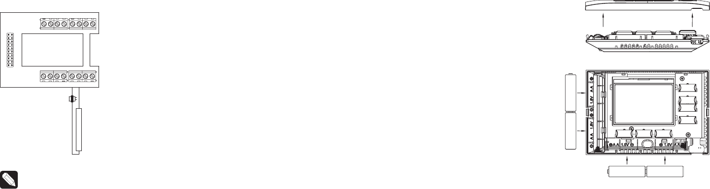
Power and battery replacement
This thermostat can be AC powered,
battery powered, or both (to provide
backup power for communication with
the Control4 system). The thermostat
uses four alkaline AA batteries. Batteries
are optional but recommended if your
thermostat was wired to run on AC power
when installed. If the thermostat will be
AC powered, the thermostat should be
powered from 24VAC before installing
batteries to confirm AC power is present.
For heat pump systems, the C terminal
must be connected to the common of the
24VAC transformer for the system fault
indicator to operate.
The thermostat has a memory backup that
saves the thermostat settings in case of
a power interruption. The system settings
will be retained, but the clock resets after
both battery and AC power are removed.
Clock synchronization comes from the
connection to the Control4 system. To
access the batteries for replacement,
remove the bezel as shown.
18 19
Setup and testing
Setup and testing
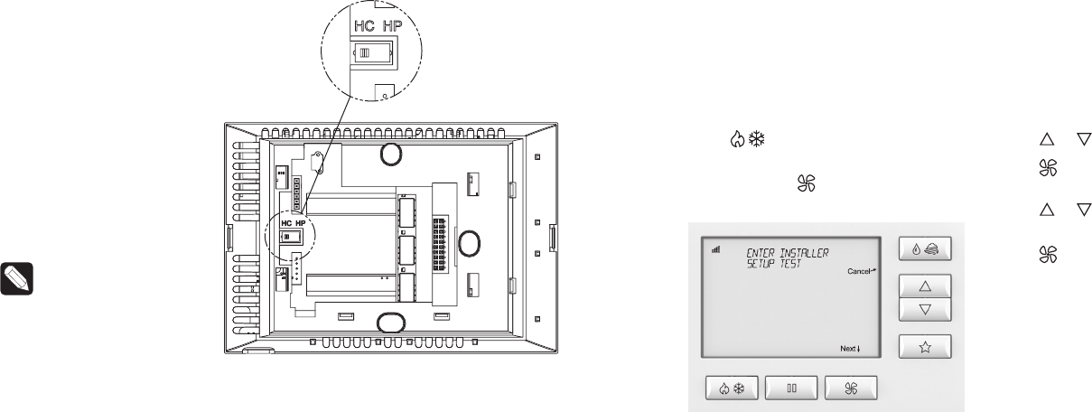
Equipment Type
selection switch
This thermostat has the
option of being used in heat
pump or heat/cool systems.
Use the Equipment Type
selection switch on the back
of the thermostat housing to
select this option. This setting
is displayed in the thermostat’s
Installer System Settings menu
under Equipment Type.
Note: The thermostat
reboots within 10
seconds after the
switch position is
changed.
Installer Setup menu
To enter the Installer Setup menu and select equipment to set up:
In the Installer Setup menu, you can select HVAC or Indoor Air Quality Setup.
If Indoor Air Quality Setup is selected, you can then set up Air Cleaning,
Humidification, Dehumidification, or Ventilation.
Press button to set system to
OFF.
Press and hold button to enter
Installer Mode.
Press or buttons to select SETUP.
Press button (Next) to enter
Installer Setup.
Press or buttons to change the
menu selections.
Press button (Next) to accept the
menu selection.
Note:
Select HC (Heat Cool)
or HP (Heat Pump).
20 21
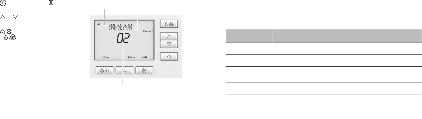
Setup and testing
Change system settings
Press button (Next) or button
(Back) to page through settings.
Press or buttons to adjust the
setting.
Press button (Done) to save and
exit, or button (Cancel) to exit
without saving.
The thermostat will discard changes
and exit if nothing is pressed within
60 seconds.
To reset the system settings to
default, set system setting number 31
(Restore Defaults) to Yes.
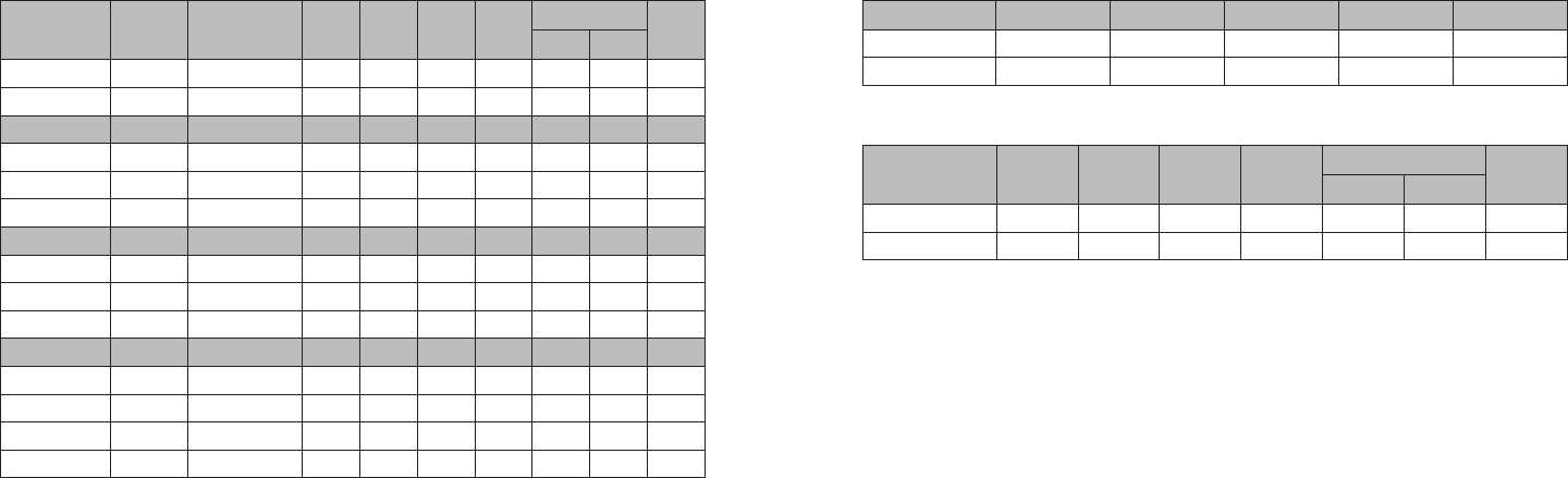
HVAC Installer system settings table
The following table contains the system settings and their details. Default
settings are shown in bold. Some settings are only available based upon the
value of other settings.
HVAC Installer system settings table
System setting Description
Factory default setting
(bold) and setting range
00. Equipment Type Equipment type set by Equipment Type
selection switch.
Heat/Cool
Heat Pump
01. Reversing Value Selects O or B operation for the O/B output. O—On in Cooling
B—On in Heating
02. Control Setup Used to lock out heating or cooling outputs
(only available when Equipment Type is
Heat/Cool).
Heat and Cool
Heat Only
Cool Only
03. Number of Stages Number of equipment stages. One
Two
04. Aux Heat Stages Number of auxiliary heat equipment stages. One
Two
05. Temperature Scale Sets the thermostat for Fahrenheit or Celsius
operation.
Fahrenheit
Celsius
Setting
number
Setting
description
Setting
option

22 23
Setup and testing
HVAC Installer system settings table
System setting Description
Factory default setting
(bold) and setting range
06. Heat/Cool:
Fan Control in
Heating
Heat Pump:
Auxiliary
Equipment Type
Heat/Cool: Determines if the thermostat or
equipment controls the fan in heating.
Heat Pump: Auxiliary equipment type.
Gas/Oil Heat
(Equipment Controls Fan)
Electric Heat
(Thermostat Controls Fan)
07. Extended Fan—
Heat
Extends the fan run time after a heat call ends. Disable
Enable (90 second extension)
08. Extended Fan—
Cool
Extends the fan run time after a cool call ends. Disable
Enable (90 second extension)
09. Internal
Temperature
Sensor Oset
Field adjustment of internal temperature
sensor.
0° (no oset applied)
-4°F to +4°F (-2°C to +2°C)
10. Internal RH Sensor
Oset
Field adjustment of internal humidity sensor. 0% (no oset applied)
-5% to +5%
11. Auto Changeover Enables or disables the option of setting
the system mode to Auto. When the system
mode is set to Auto, the thermostat can
automatically switch between heating and
cooling to maintain a room temperature that is
between the heat and cool setpoints.
Disable
Enable
12. Deadband Auto season changeover deadband. 3°F or 1.5°C
2°F to +9°F (1°C to 4.5°C)
HVAC Installer system settings table
System setting Description
Factory default setting
(bold) and setting range
13. Remote Sensor Selects if the wired remote sensor is installed. No
Yes
14. Primary Sensor Selects the primary sensor to be used for
temperature control.
Built In
Remote
15. Secondary Sensor Selects the sensor to be used for control if
the primary sensor fails. Remote will only be
presented as an option if Remote Sensor is
set to Yes.
None
Remote
Built In
16. Outdoor Sensor Selects if an outdoor sensor is installed or if
the thermostat receives an outdoor sensor
value from the Control4 system.
Not Installed
Wired
Control4 Value
17. Compressor Min O
Time
Minimum o time for compressor protection. 5 minutes
1 to 5 minutes
18. Heating Min O
Time
Minimum o time for heating. 2 minutes
1 to 5 minutes
19. Equipment Min On
Time
Minimum on time for heating or cooling. 2 minutes
1 to 5 minutes
20. Auto Changeover
Time
Minimum time between heating and cooling
calls.
4 minutes
1 to 5 minutes

24 25
Setup and testing
HVAC Installer system settings table
System setting Description
Factory default setting
(bold) and setting range
21. First Stage
Dierential
Temperature dierence from the setpoint
required to turn on the first stage of heating
or cooling.
1°F or 0.5°C
1°F to +9°F (0.5°C to 4.5°C)
22. Second Stage
Dierential
Temperature dierence required to stage from
the first stage of heating or cooling to the
second.
1°F or 0.5°C
1°F to +9°F (0.5°C to 4.5°C)
23. Third Stage
Dierential
Temperature dierence required to stage from
the second stage of heating to the third.
1°F or 0.5°C
1°F to +9°F (0.5°C to 4.5°C)
24. Fourth Stage
Dierential
Temperature dierence required to stage from
the third stage of heating to the fourth.
1°F or 0.5°C
1°F to +9°F (0.5°C to 4.5°C)
25. Stage Rate Accumulation of equipment run time used for
determining equipment staging.
O = Ignores accumulated runtime in staging
decision.
1 = More rapid staging of equipment (comfort).
5 = Slower staging of equipment (economy).
2
1 to 5 or O
26. Progressive
Recovery
Enables or disables progressive recovery.
If progressive recovery is enabled, the
equipment will turn on before the next
scheduled event so that the space reaches the
desired schedule temperature at the start of
the next event.
Disable
Enable
HVAC Installer system settings table
System setting Description
Factory default setting
(bold) and setting range
27. Low Balance Point Low balance point is the outdoor temperature
at which the compressor will be locked out
and only auxiliary heat will be used for heating.
This option is not displayed unless Outdoor
Sensor is set to Wired or Control4 Value and
Equipment Type is set to Heat Pump.
20°F or -6°C
10°F to 50°F (-12°C to 12°C)
28. High Balance Point High balance point is the outdoor temperature
at which the auxiliary heat will be locked out
and only the compressor will be used for
heating. This option is not displayed unless
Outdoor Sensor is set to Wired or Control4
Value and Equipment Type is set to Heat
Pump.
65°F or 18°C
40°F to 85°F (3°C to 30°C)
29. Reset Service
Reminders
Clears the Change Air Filter, HVAC Service,
and Dehumidifier Service reminders if they are
active and resets the corresponding service
timer. Clears the Change Water Panel reminder
if it is active. If the reminder is set to 300 hours
or 600 hours, the service timer is reset.
No
Yes
30. HVAC Service
Reminder
Elapsed time to display the HVAC Service
Reminder message.
O
1 to 12 months or O to
disable.
31. Restore Defaults Resets all thermostat settings back to factory
default.
No
Yes
26 27
Setup and testing
Indoor Air Quality system settings tables
The following tables contain the Indoor Air Quality system settings and their
details. Default settings are shown in bold. Some settings are only present
dependent upon the value of other settings.
The use of the included outdoor temperature sensor (recommended) enables
additional Indoor Air Quality functionality. If the outdoor temperature sensor
was not enabled in the HVAC system settings, HVAC system setting 16 (Outdoor
Sensor) will be presented before entering the Indoor Air Quality system settings.
Refer to the User Guide for further information about thermostat features.
Air cleaning system settings table
System setting Description
Factory default setting
(bold) and setting range
Air Cleaner Installed Selects if an air cleaner is installed. (If set to
No, no other air cleaning settings are available.)
No
Yes
Change Air Filter
Reminder
Elapsed time to display the “Change Air Filter”
message.
O
1 to 12 months or “O” to disable
Humidifier system settings table
Note: A humidifier can be installed only if ventilation is not installed and Dehumidifier Control is not set to
Whole Home.
System setting Description
Factory default setting
(bold) and setting range
Humidifier Installed Selects if a humidifier is installed. (If set to No,
no other humidifier settings are available.)
No
Yes
Humidifier Mode Selects Auto or Manual mode. Auto mode
controls humidity based on the humidity setting
and outdoor temperature. Manual mode controls
humidity based on the %RH setpoint. (Auto
mode is available only if Outdoor Sensor is set
to Ye s .)
Auto
Manual
Humidity Setpoint
Deadband
Selects the minimum dierence between the
humidifier and dehumidifier setpoints. (Only
available if Humidifier Installed is set to Yes, and
Dehumidifier Control is set to Air Conditioner.
Available in both setups.)
10 Percent RH
10 to 20 Percent RH
Humidifier Operation Selects when humidification is allowed to occur
relative to heating and fan operation.
Heat Only
Heat or Fan
Forces Fan
Change Water Panel
Reminder
Selects when the “Change Water Panel” message
is displayed.
O
1 Per Season
2 Per Season
300 Hours
600 Hours

28 29
Setup and testing
Humidifier system settings table
Note: A humidifier can be installed only if ventilation is not installed and Dehumidifier Control is not set to
Whole Home.
System setting Description
Factory default setting
(bold) and setting range
Reminder Month
(Change Water Panel
Reminder set to 1 Per
Season)
First Reminder Month
(Change Water Panel
Reminder set to 2 Per
Season)
If Change Water Panel Reminder is set to 1 Per
Season: Determines the month the “Change
Water Panel” message is displayed.
If Change Water Panel Reminder is set to 2 Per
Season: Determines the first month the “Change
Water Panel” message is displayed.
October
November
December
January
February
March
April
May
June
July
August
September
Second Reminder
Start Month
Determines the second month the “Change
Water Panel” message is displayed. (Only
available when Change Water Panel Reminder
set to 2 Per Season.)
October
November
December
January
February
March
April
May
June
July
August
September
Dehumidifier system settings table
Note: Dehumidifier Control can only be set to Whole Home if ventilation and humidification are not installed.
System setting Description
Factory default setting
(bold) and setting range
Dehumidifier Control Selects method of dehumidification. (If set
to None, no other dehumidifier settings are
available.)
None (no dehumidification
installed)
Whole Home
Air Conditioner
Humidity Setpoint
Deadband
Select the minimum dierence between the
humidifier and dehumidifier setpoints. (Only
available if Humidifier Mode is set to Manual and
Dehumidifier Control is set to Air Conditioner.
Available in both setups.)
10 Percent RH
10 to 20 Percent RH
Lockout Dehumidifier
During Cooling
Selects if dehumidification is disabled during
a cooling call. (Only available if Dehumidifier
Control is set to Whole Home.)
No
Yes
Dehumidifier Forces
Fan
Selects if dehumidification can turn on the fan.
(Only available if Dehumidifier Control is set to
Whole Home.)
No
Yes
Dehumidifier Service
Reminder
The period for displaying the “Dehum Service
Reminder” message. (Only available if
Dehumidifier Control is set to Whole Home.)
O
1 to 12 months or “O” to
disable
Dehumidifier
Overcooling Limit
Selects the amount of overcooling that can
occur for dehumidification. (Only available if
Dehumidifier Control is set to Air Conditioner.)
3°F (1.5°C)
1°F to 3°F (0.5°C to 1.5°C)

30 31
Setup and testing
Ventilation system settings table
Note: Ventilation can be installed only if humidification is not installed and Dehumidifier Control is not set
to Whole Home.
System setting Description
Factory default setting
(bold) and setting range
Fresh Air Vent
Installed
Selects if ventilation is installed. (If set to No, no
other ventilation settings are available.)
No
Yes
Fresh Air Forces
Fan
Selects if ventilation forces the fan on. No
Yes
Fresh Air Setup Selects if ventilation is configured through the
ASHRAE setup or Timed. If ASHRAE setup is
selected, the hourly ventilation time is calculated
using the ASHRAE recommendations. If Timed
setup is selected, the hourly ventilation time is
determined based on the Fresh Air Time value.
Timed
ASHRAE
Fresh Air Time Selects the number of minutes per hour that
ventilation will be active. (Only available if Fresh
Air Setup is set to Timed.)
30 MIN/HR
0 to 60 MIN/HR
High Limit Outdoor
Temp
Selects if ventilation is disabled when the outdoor
temperature exceeds the outdoor high limit. (Only
available if Fresh Air Setup is set to Timed and an
outdoor temperature sensor is installed.)
No
Yes
Outdoor High Limit Sets the high temperature limit for ventilation.
(Only available if High Limit Outdoor Temp is set
to Ye s .)
100°F (38°C)
90°F to 100°F (32°C to 38°C)
Ventilation system settings table
Note: Ventilation can be installed only if humidification is not installed and Dehumidifier Control is not set
to Whole Home.
System setting Description
Factory default setting
(bold) and setting range
Low Limit Outdoor
Temp
Selects if ventilation is disabled when the outdoor
temperature exceeds the outdoor low limit. (Only
available if Fresh Air Setup is set to Timed and an
outdoor temperature sensor is installed.)
No
Yes
Outdoor Low Limit Sets the low temperature limit for ventilation.
(Only available if Low Limit Outdoor Temp is set
to Ye s .)
10°F (-11°C)
-10°F to 30°F (-23°C to -1°C)
High Limit Indoor
RH
Selects if ventilation is disabled when the indoor
RH exceeds the indoor RH limit. (Only available if
Fresh Air Setup is set to Timed.)
No
Yes
Indoor RH Limit Sets the high indoor RH limit for ventilation. (Only
available if High Limit Indoor RH is set to Yes.)
60%
50% to 70%
Number of
Bedrooms
Selects the number of bedrooms to be used for
the ASHRAE calculation. (Only available if Fresh
Air Setup is set to ASHRAE.)
3 Bedrooms
1 to 6 Bedrooms
Number of
Occupants
Selects the number of occupants to be used for
the ASHRAE calculation. (Only available if Fresh
Air Setup is set to ASHRAE.)
4 Occupants
1 to 10 Occupants
32 33
Setup and testing
Ventilation system settings table
Note: Ventilation can be installed only if humidification is not installed and Dehumidifier Control is not set
to Whole Home.
System setting Description
Factory default setting
(bold) and setting range
Home Size Selects the home size to be used for the ASHRAE
calculation. If multiple ventilation systems are
used, this should be set to the size of the zone
that this thermostat is controlling. (Only available
if Fresh Air Setup is set to ASHRAE.)
2500 SQ FT
1000 to 5000 SQ FT
Fresh Air CFM Selects the ventilation CFM to be used for the
ASHRAE calculation. (Only available if Fresh Air
Setup is set to ASHRAE.)
60 CFM
30 to 200 CFM
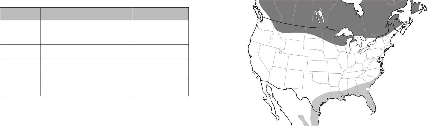
Select Climate Selects the climate to be used for the ASHRAE
calculation. (Only available if Fresh Air Setup is
set to ASHRAE.) To determine what region you
are in, refer to the map on the following page.
Normal
Very Hot/Humid
Very Cold
ASHRAE Cycle Time Displays the Fresh Air Time calculated by the
ASHRAE standard. (Only displayed if Fresh Air
Setup is set to ASHRAE.)
Minutes/Hour
Note: In ASHRAE setup, temperature and humidity limits are disabled.
Note: Refer to manuals for humidifier, dehumidifier, air cleaner, and ventilation products for recommended
installation and operation.
Climate map for ASHRAE Fresh Air Setup
Very hot/humid
Very cold
34 35
Setup and testing
Function Button Sequence
Identify 4
ZigBee Channel 7
Reboot 15
Factory Reset* 9-4-9
Leave Mesh and Reset* 13-4-13
* The thermostat’s HVAC and Indoor Air Quality
system settings will not be reset.
Managing the ZigBee network connection
The thermostat utilizes special button
tap sequences for managing the ZigBee
network connection. The button tap
sequences are defined in the table.
Button tap sequences that require a
single (1) button should use the
button on the top right of the thermostat.
Button tap sequences requiring two (2)
buttons should use the button and
the button on the bottom right
of the thermostat.
System Test menu
The System Test menu is used to
test a system after installation. The
outputs of the thermostat can be
manually activated to test their
function. The instructions below show
how to enter the test mode and turn
outputs on and o.
To use the System Test menu:
Press button to set the system
to o.
Press and hold button to enter
Installer Mode.
Press or buttons to select TEST.
Press button (Next) to enter
Installer Test. The first screen of the
installer test displays the equipment
configuration.
Press button (Next) to enter the
first installation test or button
(Cancel) to exit.
System Test steps:
Heating equipment test
Cooling equipment test
Fan equipment test
Humidification equipment test
Dehumidification equipment test
Ventilation equipment test
Temperature
Single-button tap
sequences
Two-button tap
sequences
Equipment
configuration
36 37
Setup and testing
Each equipment test begins with the option of turning on the output or stage as
shown below.
Press or button to change the selection.
Press button (Next) to accept the selection and proceed to the next step.
If YES is selected, the thermostat tests the corresponding output. If NO is
selected, the thermostat proceeds to the next step.
Temperature
Equipment Test
selection
Test to be run
While the equipment test is active, the corresponding test information is shown.
Press button (Next) to accept the selection and proceed to the next test selection.
Output status
Equipment Test
selection
Temperature
Active test
38 39
Setup and testing
System Test tables
Heat/cool heating equipment test
Heat type W W2 Y Y2 G
Gas 1st Stage Test ON
Gas 2nd Stage Test ON ON
Electric 1st Stage Test ON ON
Electric 2nd Stage Test ON ON ON
Heat pump heating equipment test (electric heat)
Compressor
stages
Aux
stages W W2 Y Y2
O/B set to
GO B
1 1 1st Stage Test ON ON ON
1 1 2nd Stage Test ON ON ON ON
2 1 1st Stage Test ON ON ON
2 1 2nd Stage Test ON ON ON ON
2 1 3rd Stage Test ON ON ON ON ON
1 2 1st Stage Test ON ON ON
1 2 2nd Stage Test ON ON ON ON
1 2 3rd Stage Test ON ON ON ON ON
2 2 1st Stage Test ON ON ON
2 2 2nd Stage Test ON ON ON ON
2 2 3rd Stage Test ON ON ON ON ON
2 2 4th Stage Test ON ON ON ON ON ON
Note: System variable 01, O/B operation selects O or B.
40 41
Setup and testing
Heat pump heating equipment test (gas heat)
Compressor
stages
Aux
stages W W2 Y Y2
O/B set to
GO B
1 1 1st Stage Test ON ON ON
1 1 2nd Stage Test ON ON
2 1 1st Stage Test ON ON ON
2 1 2nd Stage Test ON ON ON ON
2 1 3rd Stage Test ON ON
1 2 1st Stage Test ON ON ON
1 2 2nd Stage Test ON ON
1 2 3rd Stage Test ON ON ON
2 2 1st Stage Test ON ON ON
2 2 2nd Stage Test ON ON ON ON
2 2 3rd Stage Test ON ON
2 2 4th Stage Test ON ON ON
Note: System variable 01, O/B operation selects O or B.
Heat/cool cooling equipment test
W W2 Y Y2 G
1st Stage Test ON ON
2nd Stage Test ON ON ON
Heat pump cooling equipment test
W W2 Y Y2
O/B set to
GO B
1st Stage Test ON ON ON
2nd Stage Test ON ON ON ON
Note: System variable 01, O/B operation selects O or B.
42 43
Setup and testing
Fan equipment test
W W2 Y Y2 G
ON
Humidification equipment test
I1/ I2 G
ON ON
Dehumidification equipment test
I1/ I2 G
ON ON
Ventilation equipment test
I1/ I2 G
ON ON
Quick reference to controls and display
Home screen
Note: Backlight is activated with the first button press and automatically turns o.
Equipment
status
System Mode
setting
System Mode button Hold button Fan Mode button
Indoor Air Quality
button (optional)
Setpoint Adjust
buttons
Temperature
setting
Fan Mode setting
Presets button
Hold status
Radio signal
strength indicator
Low battery
indicator
Message
center
Indoor Air
Quality setting
Current indoor
temperature
Quick reference to controls and display

44 45
Troubleshooting
Troubleshooting
Display is blank
• Check the circuit breaker and reset it if necessary.
• Make sure the heating and cooling system’s power switch is on.
• Make sure the furnace door is closed securely.
• If the thermostat is battery powered, make sure that fresh AA alkaline
batteries are correctly installed.
Temperature settings do not change
Make sure heating and cooling temperatures are set to acceptable ranges:
• Heat: 40° to 90°F (4° to 32°C).
• Cool: 50° to 99°F (10° to 37°C).
Heating system does not respond ( appears on screen)
• Check for 24VAC at the equipment on the secondary side of the transformer
between power and common. If voltage is not present, check the heating
equipment to find the cause of the problem.
• Check for 24VAC between the heat terminal (W) and the transformer
common. If 24VAC is present, the thermostat is functional. Check the heating
equipment to find the cause of the problem.
• Check for loose or broken wires between the thermostat and the heating
equipment.
Cooling system does not respond ( appears on screen)
• Check for 24VAC at the equipment on the secondary side of the transformer
between power and common. If voltage is not present, check the cooling
equipment to find the cause of the problem.
• Check for 24VAC between the cooling terminal (Y) and the transformer
common. If 24VAC is present, the thermostat is functional. Check the cooling
system to find the cause of the problem.
• Check for loose or broken wires between the thermostat and the cooling
equipment.
Fan does not turn on in a call for heat
• Check System Setting 06 (Fan Control) to make sure the fan control is
properly set to match the type of system (see page 22).
Heat pump issues cool air in heat mode or warm air in cool mode
• Check System Setting 01 (O/B Operation) to make sure the reversing valve
operation matches the heat pump.
Heat/Cool both on at the same time
• Check the Equipment Type selection switch to make sure it is set to match the
installed heating/cooling equipment (see page 21).
• Make sure the heating and cooling wires are not shorted together.

46 47
Troubleshooting
Heating equipment is running in cool mode
• Check the Equipment Type selection switch to make sure it is set to match
the installed heating/cooling equipment (see page 21).
is not displayed
• Make sure that Installer System Setting number 02 (Control Setup) is set
correctly.
• Change the System Mode to Heat, and set the temperature level above the
current room temperature.
is not displayed
• Make sure that Installer System Setting number 02 (Control Setup) is set
correctly.
• Change the System Mode to Cool, and set the temperature level below the
current room temperature.
Humidifier does not operate in Auto Mode
• Make sure that Installer System Setting number 16 (Outdoor Sensor) is set
to Ye s.
• Verify that the outdoor sensor is functioning correctly. If the sensor failed,
you will see a “CHECK OUTDOOR SENSOR” message displayed in the
message center.
Error codes
Error codes
If the thermostat enters an error mode, all outputs are turned o. The thermostat
attempts to recover every 10 minutes.
Error code Message Error Description
01
“SENSOR ERROR”
Primary sensor failure with no secondary sensor assigned.
02 Primary and secondary sensor failure.
03 “EEPROM ERROR” Error in permanent memory.
48 49
Thermostat features
Thermostat features
• Up to 4 stage heat and 2 stage cool operation.
• Indoor air quality control.
• Humidification (automatic or manual control).
• Dehumidification.
• Event-Based™ air cleaning.
• Ventilation with temperature and humidity limits.
• Temperature control.
• Message center provides feedback and instructions.
• Dual power option (24VAC or battery).
• Air filter, humidifier, dehumidifier, and HVAC service reminders.
• Programmable fan control with fan circulation mode.
• Easy-to-use temperature control can override program schedule at any time.
• Progressive recovery ensures proper temperature at the start of a program event.
• Built-in compressor protection prevents damage to your equipment.
• System test mode.
Specifications
Specifications
Environment
Temperature Operating: 32° to 120°F (0° to 48.9°C)
Shipping: -30° to 150°F (-34.4° to 65.5°C)
Relative humidity Operating: 5% to 90% R.H. (non-condensing)
Electrical
Operating voltage 24VAC (19.2–28.8VAC)
Current Maximum: 2.5A (total), 1.0A (single output)
Maximum surge current: 5A
Power supply Dual power. Can be battery or 24VAC powered.
When both sources are available, the battery is used as backup power.
Battery power Battery power: AA size alkaline battery x 4
Battery life: Approximately 12 months
50 51
Specifications
Thermal
Outdoor and Remote temperature sensor Maximum distance: 300 feet (about 100 meters)
Room temperature measurement Display range: 32° to 99°F (0° to 40°C)
Outdoor temperature measurement Display range: -40° to 130°F (-40° to 55°C)
Setpoint temperature range Heat: 40° to 90°F (4° to 32°C)
Cool: 50° to 99°F (10° to 37°C)
Setpoint humidity range Humidification: 10% to 50% R.H.
Dehumidification: 40% to 90% R.H.
U.S. Patent Number 8,146,376 (and other patents pending).

control4.com | 888.400.4070 61001048 B2206227B 2.14

Regulatory Compliance & Safety Information for Contol4 Model C4-THERM-XX.
USA & Canada Compliance
FCC Part 15, Subpart B Unintentional Emissions Interference Statement
This equipment has been tested and found to comply with the limits for a Class B digital device,
pursuant to Part 15 of the FCC rules. These limits are designed to provide reasonable protection
against harmful interference when the equipment is operated in a residential installation. This
equipment generates uses and can radiate radio frequency energy and, if not installed and used
in accordance with the instructions, may cause harmful interference to radio communications.
However, there is no guarantee that interference will not occur in a particular installation. If this
equipment does cause harmful interference to radio or television reception, which can be
determined by turning the equipment off and on, the user is encouraged to try to correct the
interference by one or more of the following measures:
• Reorient or relocate the receiving antenna.
• Increase the separation between the equipment and receiver.
• Connect the equipment into an outlet on a circuit different from that to which the receiver
is connected.
• Consult the dealer or an experienced radio/TV technician for help.
FCC Partie 15, sous-section B Unintentional Déclaration sur les interférences des
émissions
Cet équipement a été testé et jugé conforme aux limites établies pour un dispositif numérique de
classe B, conformément à la Partie 15 des règlements de la FCC. Ces limites sont conçues pour
fournir une protection raisonnable contre les interférences nuisibles lorsque l'équipement est
utilisé dans une installation résidentielle. Cet équipement génère, utilise et peut émettre de
l'énergie rayonnent fréquence et, s'il n'est pas installé et utilisé conformément aux instructions, il
peut causer des interférences nuisibles aux communications radio. Cependant, il n'existe aucune
garantie que des interférences ne se produiront pas dans une installation particulière. Si cet
équipement provoque des interférences nuisibles à la réception radio ou télévision, ce qui peut
être déterminé en mettant l'équipement hors et sous tension, l'utilisateur est encouragé à essayer
de corriger l'interférence par une ou plusieurs des mesures suivantes:
• Réorienter ou déplacer l'antenne de réception.
• Augmenter la distance entre l'équipement et le récepteur.
• Connecter l'équipement à une prise sur un circuit différent de celui sur lequel le récepteur
est branché.
• Consulter le revendeur ou un technicien radio / télévision qualifié pour obtenir de l'aide.
This device complies with part 15 of the FCC rules and Industry Canada’s licence-exempt RSS-
GEN. Operation is subject to the following two conditions: (1) This device may not cause harmful
interference, and (2) this device must accept any interference received, including interference that
may cause undesired operation.
Le présent appareil est conforme partie 15 des règles de la FCC et aux RSS-GEN d'Industrie
Canada applicables aux appareils radio exempts de licence. L'exploitation est autorisée aux deux

conditions suivantes : (1) l'appareil ne doit pas produire de brouillage, et (2) l'utilisateur de
l'appareil doit accepter tout brouillage radioélectrique subi, même si le brouillage est susceptible
d'en compromettre le fonctionnement.
IMPORTANT! Any changes or modifications not expressly approved by the party responsible for
compliance could void the user’s authority to operate this equipment.
IMPORTANT! Tous les changements ou modifications pas expressément approuvés par la partie
responsable de la conformité ont pu vider l’autorité de l’utilisateur pour actionner cet équipement.
FCC Part 15, Subpart C / RSS-210 Intentional Emissions Interference Statement
Compliance of this equipment is confirmed by the following certification numbers that are placed
on the equipment:
Notice: The term “FCC ID:” and “IC” before the certification number signifies that FCC and
Industry Canada technical specifications were met.
FCC ID: R33C4THERM
IC: 7848A-C4THERM
This equipment must be installed by qualified professionals or contractors in accordance with
FCC Part 15.203 & IC RSS-210, Antenna Requirements. Do not use any antenna other than the
one provided with the unit.
FCC Partie 15, sous-partie C / RSS-210 Déclaration volontaire des émissions interférences
Conformité de cet appareil est confirmé par les chiffres de certification suivants qui sont placés
sur l'équipement:
Avis: Le terme “FCC ID:” and “IC” avant le numéro de certification signifie que la FCC et Industrie
Canada ont été respectées.
FCC ID: R33C4THERM
IC: 7848A-C4THERM
Cet équipement doit être installé par des professionnels qualifiés ou entrepreneurs conformément
aux normes FCC partie 15.203 & IC RSS-210, Exigences d'antenne. Ne pas utiliser une antenne
autre que celui fourni avec l'appareil.
RF Radiation Exposure Statement
This equipment complies with the FCC/IC radiation exposure limits set fourth for portable
transmitting devices operation in an uncontrolled environment. End users must follow the specific
operating instructions to satisfy RF exposure compliance.
• The equipment should only be used or installed at locations where there is normally at
least a 20cm separation between the antenna and all persons.
• This transmitter must not be co-located or operation in conjunction with any other
antenna or transmitter.
• Any changes or modifications not expressly approved by the party responsible for
compliance could void the user’s authority to operate this equipment.
Déclaration d'exposition aux radiations RF
Cet équipement est conforme aux limites FCC / IC d'exposition aux rayonnements définies
quatrième opération appareils portables transmettre dans un environnement non contrôlé. Les

utilisateurs finaux doivent suivre les instructions de fonctionnement spécifiques pour satisfaire la
conformité aux expositions RF.
• L'appareil ne doit être utilisé ou installé à des endroits où il ya normalement au moins
une séparation de 20 cm entre l'antenne et toute personne.
• Cet émetteur ne doit pas être co-localisés ou fonctionnement en conjonction avec une
autre antenne ou un autre émetteur.
• Tout changement ou modification non expressément approuvé par la partie responsable
de la conformité pourraient annuler l'autorité de l'utilisateur à utiliser cet équipement.

European Compliance
Conformity of the equipment with the guidelines below is attested by the application of the CE
mark.
CE Declaration of Conformity
Manufacturer’s Name: CONTROL4 CORPORATION
Manufacturer’s Address: 11734 S. ELECTION ROAD SUITE 200
SALT LAKE CITY
UT 84020 USA
EU Representative Name: CONTROL4 EMEA LIMITED
EU Representative Address: UNIT3, GREEN PARK BUSINESS CENTRE
SULTON-ON-THE FOREST
YORK YO61 IET, UNITED KINGDOM
Product Name(s): Wireless Thermostat
Brand: Contol4
Model(s): C4-THERM-XX
Product Standard(s) to which Conformity of the Council Directive(s) is declared:
EMC - 2004/108/EC “Electromagnetic Compatibility (EMC) Directive”:
(Emissions) EN 55022:2010, (Immunity) EN 55024:2010, EN 301 489-1:2008, EN 301 489-
17:2009, EN 61000-3-2:2006 + A1:2009 + A2:2009 & EN 61000-3-3:2008
Telecom & Radio - 1999/5/EC Radio equipment and Telecommunications Terminal
Equipment (R&TTE) Directive:
EN 300 328 V1.7.1 (2006-10)
RoHS - 2011/65/EU Restriction of the Use of certain Hazardous Substances in Electrical
and Electronic Equipment (EEE) & WEEE - 2002/96/EC Waste of Electrical and Electronic
Equipment (EEE).
We, the undersigned, hereby declare that the equipment specified above conforms to the above
directives and standards. Date of Issue: January 9, 2015
Legal Representative
Signature
Roger Midgley
Sr. Regulatory Compliance Engineer
Recycling
Control4 understands that a commitment to the environment is essential for a health life and
sustainable growth for future generations. We are committed to supporting the environmental
standards, laws, and directives that have been put in place by various communities and countries
that deal with concerns for the environment. This commitment is represented by combining
technological innovation with sound environmental business decisions.
WEEE Compliance
Control4 is committed to meeting all requirements of the Waste Electrical and Electronic
Equipment (WEEE) directive (2002/96/EC). The WEEE directive requires the manufacturers of
electrical and electronic equipment who sell in EU countries: (1) label their equipment to notify
customers that it needs to be recycled, and (2) provide a way for their products to be
appropriately disposed of or recycled at the end of their product lifespan. For collection or
recycling of Control4 products, please contact your local Control4 representative or dealer.
About this Document
Copyright © 2015 Control4 Corporation. All rights reserved. Control4 and the Control4 logo are
registered trademarks or trademarks of Control4 Corporation in the United States and/or other countries.
Part Number 200-40003 Rev B, 1/9/2015