Snap One C4TW7C0 TOUCH SCREEN INTERFACE DEVICE User Manual
Control4 TOUCH SCREEN INTERFACE DEVICE Users Manual
Snap One >
Users Manual
™NOTE: Video Intercom using 802.11b is not
recommended or supported for Video
Intercom. Control4 recommends Wireless-N
for Video Intercom. See “Wireless Network
Limitations” and “Power and Network
Installation Options.”
• Option1:EthernetwithPoE. The Ethernet
network connection is provided through the PoE
Injector. No additional wiring is needed.
• Option2:EthernetwithAC. Connect the Touch
Screen to one of the RJ-45 LAN ports on the
gateway/router using the RJ-45 Ethernet cable.
• Option3:WiFiwithAC. The internal WiFi will
communicate with the LAN’s WAP. If the LAN has
a WAP set up, no additional wiring is needed.
Supported Models
• C4-TW7C0-BL - 7 Inch Wall Mount Capacitive
Touch Screen with Camera, Ethernet/WiFi, PoE/
Universal Voltage, Black
• C4-TW7C0-WH - 7 Inch Wall Mount Capacitive
Touch Screen with Camera, Ethernet/WiFi, PoE/
Universal Voltage, White
Associated SKUs:
• C4-TSWMC5-EG-WH – 5” In-Wall Touch Screen,
White (no camera)
• C4-TSWMC7-EG-WH – 7” In-Wall Touch Screen,
White (no camera)
• C4-TSWMC5-EG-BL – 5” In-Wall Touch Screen,
Black (no camera)
• C4-TSWMC7-EG-BL – 7” In-Wall Touch Screen,
Black (no camera)
Box Contents
Carefully unpack the contents of the box, and make
sure the following items are included. If any item is
missing or damaged, please contact your Control4
Reseller.
• 7” In-Wall Touch Screen with Camera
• Power box (used to power the Touch Screen)
• Two (2) screws to attach the power box
• Warranty card
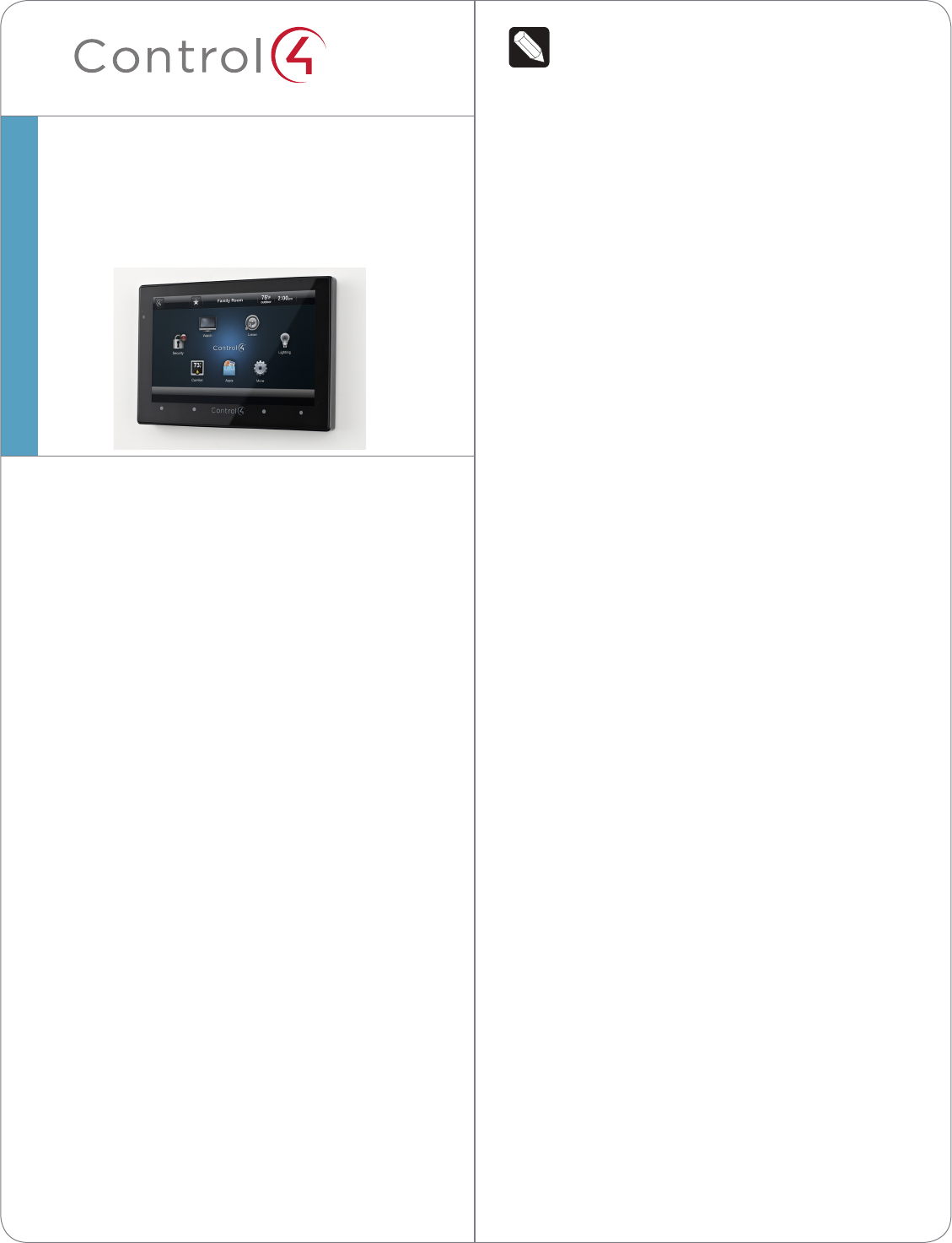
Introduction
The Control4® 7” In-Wall Touch Screen with Camera
oers complete system control in an elegant and
compact design. This Touch Screen is equipped
with a capacitive Touch Screen and four (4)
programmable shortcut buttons plus Audio and
Video Intercom (with a built-in camera) using SIP.
The available power options are AC power or Power-
over-Ethernet (PoE); the network options are WiFi
or Ethernet connections. This Touch Screen supports
new construction or retrofit installations.
• AC. AC power is used to power the Touch
Screen when using an Ethernet or WiFi network
connection.
• PoE. PoE is used to power the Touch Screen
when using an Ethernet or WiFi network
connection.
The following table shows the available network
options with power.
• Ethernet with PoE
• Ethernet with AC
• WiFi with AC
7” In-Wall Touch Screen
with Camera
Installation Guide
1
™
Accessories
• PoE. Control4 Power over Ethernet Injector, sold
separately (AC-POE1-B).
• Back Box Options. There are four (4) back
box options available for this Touch Screen’s
installation. Metal and plastic back boxes
are available for new construction or retrofit
installations.
5”and7”In-WallTouchScreenBackBoxKits-
NewConstruction
- 5” and 7” In-Wall Touch Screens Wall Box,
New Construction, Plastic (C4-NWB57C-P)
- 5” and 7” In-Wall Touch Screens Wall Box,
New Construction, Metal (C4-NWB57C-M)
5”and7”In-WallTouchScreenBackBoxKit-
Retrot
- 5” and 7” In-Wall Touch Screens Wall Box,
Retrofit, Plastic (C4-RWB57C-P)
- 5” and 7” In-Wall Touch Screens Wall Box,
Retrofit, Metal (C4-RWB57C-M)
See the Control4 5” or 7” In-Wall Touch Screen
Wall Box Installation Guide - New Construction or
5” or 7” In-Wall Touch Screen Wall Box Installation
Guide - Retrofit for back box installation details.
Specifications
Screen 7” 16:9 wide VGA Color LCD Module
Resolution: 800 x 480
Camera: 640 x 480 VGA
Brightness: 350 nits
Wireless Built In IEEE802.11 b/g/n Wireless LAN
Integral Antenna (b/g/n supported)
Authentication: WEP, WPA, WPA2
7” In-Wall Touch Screen
with Camera
Installation Guide
Dimensions
(H x W x D)
4.88” x 7.2” x .60” (124 mm x 183 mm x
15.24 mm)
Weight 1.15 lbs. (.52 kg)
Shipping Weight 1.8 lbs. (.81 kg)
Network WiFi (802.11 b/g/n) wireless access
point (WAP) already configured
to communicate with a Control4
Controller (e.g., HC-800). Wireless-N is
recommended for Video Intercom.
Notes: (1) Intercom usage. 802.11b is not
recommended or supported for Video
Intercom. (2) Wireless-N is recommended
for Video Intercom. Even with Wireless-N,
broadcasting to several devices will
degrade Video Intercom response time and
images. Broadcasting to additional devices
will further degrade performance. See
“Wireless Network Limitations.”
Requirements
To install the 7” In-Wall Touch Screen with Camera,
Control4 requires the following:
• A Home Controller fully installed and configured
with a Control4® system.
• Control4 7” Touch Screen custom back box
installed (OS 2.2.1 or later). See “Accessories.”
• IfusingEthernetwithPoEpower:
- Ethernet network installed and available that
includes a gateway/router/switch
- Control4 PoE Injector (model #AC-POE1-B)
or another third-party PoE Injector or switch
(certified to UL/ANSI standards).
- Two (2) Ethernet CAT5 cables: (1) one that
runs from the Ethernet gateway/router/switch
to the PoE Injector/switch and (2) one that runs
from the PoE Injector/switch to the Ethernet
connection in the Touch Screen’s back box.
• IfusingEthernetwithACpower:
- Ethernet network installed and available that
includes a gateway/router/switch
- Access to in-wall AC power (a neutral
connection is required)
- One (1) Ethernet CAT5 cable that runs from
the Ethernet gateway/router/switch to the Touch
Screen
- A 14-gauge electrical wire long enough to pull
between the Touch Screen and the power source
• IfusingwirelesswithACpower:
- Wireless network (WiFi 802.11 b/g/n) installed
and available with a wireless access point (WAP)
- Access to in-wall AC power (a neutral
2
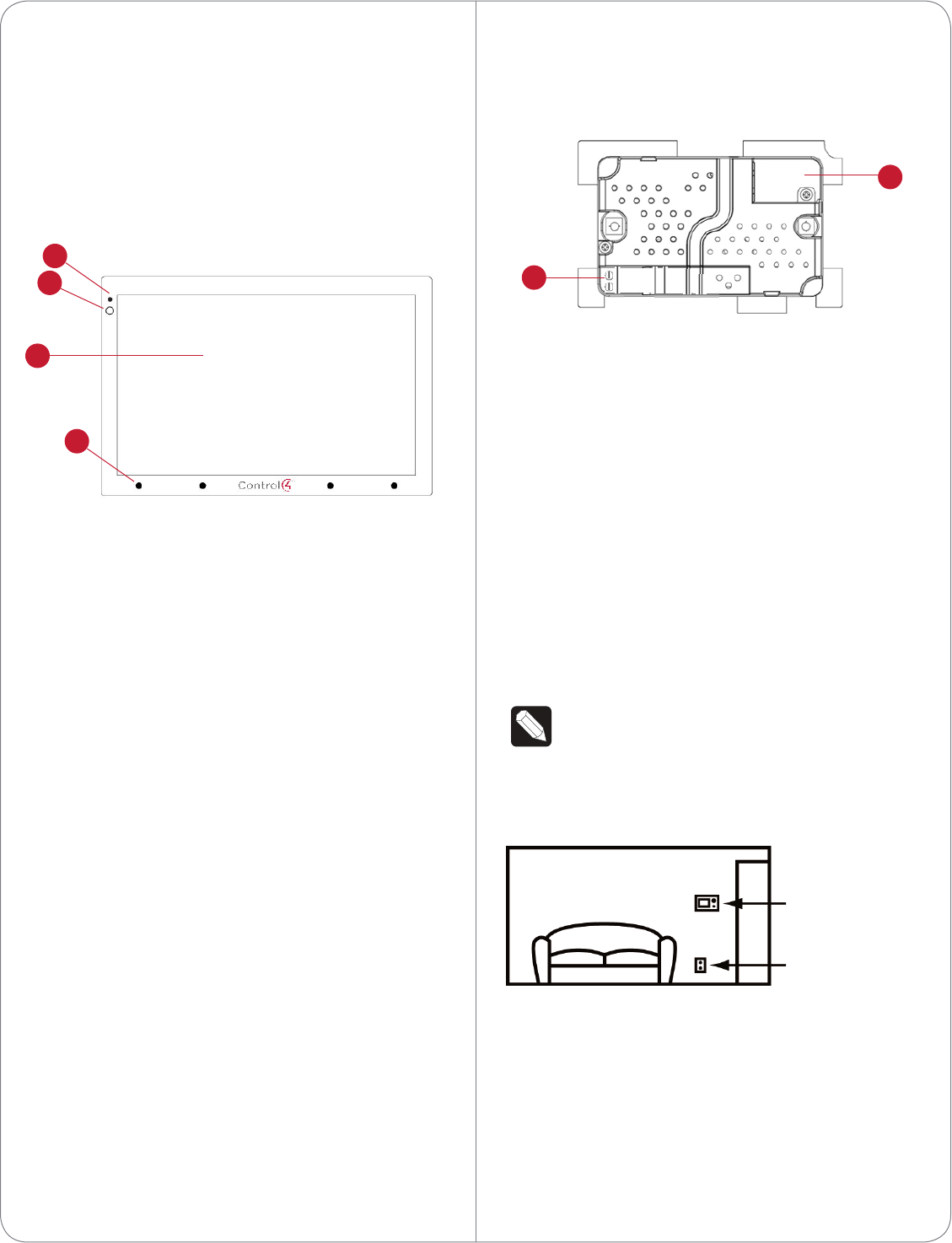
BackView
Figure 2. Back View - 7” In-Wall Touch Screen with
Camera and Power Box
1 Wire Connection. Hot (H) uses Black wire; Return
(R) uses White wire.
2 RJ-45 port for Ethernet Connection. Ethernet
port available for either a standard Ethernet
source that provides network communication
only OR a PoE source that provides power to the
device and network communication.
Touch Screen Placement
Place the Touch Screen in a convenient location at
eye level, typically near the entrance of the room,
approximately 57 to 61 inches (145 cm to 155 cm)
from the floor (see Figure 3).
NOTE: Consider the camera on the panel and
the height of the people in the home who will
use the camera for Video Intercom.
Figure 3. Touch Screen Placement
LED Indicator
The LED on the Touch Screen indicates the camera
status of the camera and booting information as
described in the next table.
connection is required)
- A 14-gauge electrical wire long enough to pull
between the Touch Screen and the power source
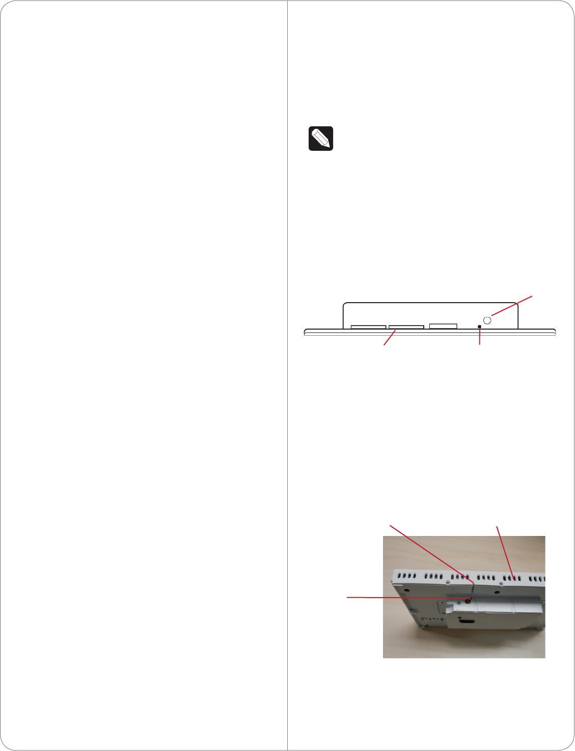
Front and Rear Panel Descriptions
FrontView
Figure 1. Front View - 7” In-Wall Touch Screen
1 Display. 7” viewing area, Touch Screen with 800 x
480 resolution.
2 Shortcut buttons (4). For custom programming;
to initiate an action or sequence of actions. Use
Composer Pro or Composer HE to configure
these buttons.
3 Green LED. Lets you know the camera is on.
4 Camera. For Video Intercom calls.
Dimensions
- Front dimensions. 7” Touch Screen (H x W x D):
4.88” x 7.2” x .60” (124 mm x 183 mm x
15.24 mm)
- Back box dimensions. 7” Touch Screen
(H x W x D): 2.7” x 4.1” x 2.4” (68 mm x 104 mm
x 61 mm)
- Power box dimensions. 7” Touch Screen (H x W
x D): 2.8” x 4.5” x 1.8” (71 mm x 114 mm x 46 mm)
Touch Screen Removal
Use the small hole located under the Touch Screen to
remove the Touch Screen from the wall (for details,
see Figure 10 in “Troubleshooting”).
3
New Device
AC Power
(unless using PoE)
2
3
4
1
1
2
CAUTION! Do not attempt to use PoE and
AC power at the same time. Choose only one
power option.
ATTENTION! Ne pas tenter d’utiliser PoE et
AC en même temps. Choisir une seule option
d’alimentation.
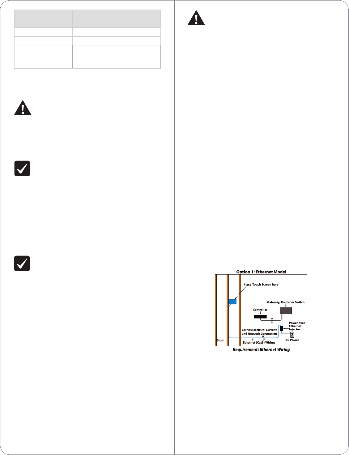
Option1:EthernetConnectionwithaPoEInjectoror
aThird-PartyInjectororSwitch
PoE supplies DC power on the Ethernet cable using
a PoE Injector (model #AC-POE1-B) or a third-party
PoE solution to provide the Touch Screen with power
and a network connection. The Touch Screen works
with the Control4 PoE Injector or a third-party PoE
Injector.
To set up your PoE and Ethernet connection with a
PoE Injector, see Figure 4.
1 Attach the PoE Injector according to the
instructions in your PoE’s installation guide if
provided. Control4 PoE Injector instructions are
provided later in this document.
2 Pull the Ethernet cable from that location to
where you want to install the Touch Screen.
Figure 4. Ethernet with PoE - Requires Ethernet
Connection to PoE Injector
Option2:EthernetConnectionwithAC
The Ethernet is connected directly to the switch
(see Figure 5). This power connection requires both
neutral and hot connections.
CameraLEDColor/
State
TouchScreenStatus
O - Camera is o
Green - Camera is on
Green (blinks slowly) - Booting up
Green (blinks
rapidly)
- Restoring (during a factory
restore)
Installation
WARNING! Before installing the Touch Screen,
switch o the circuit breaker or remove the
fuse from the fuse box.
AVERTISSEMENT! Pour l’endroit où vous
installez l’écran tactile, coupez le disjoncteur
ou enlevez le fusible de la boîte de fusible.
IMPORTANT! Before you can complete the
instructions below, you must have a 7” Touch
Screen back box installed according to the
documentation provided in the back box kit.
See “Accessories” for details.
IMPORTANT! En coupant l’ouverture pour la
boîte de mur, ne coupez pas l’ouverture trop
grande. Soyez conservateur et agrandissez-
avec précaution la comme nécessaire. Voyez
que <<Accessories>>.
IMPORTANT! When cutting the opening for
the back box, DO NOT cut the opening too
large. Be conservative and cautiously enlarge it
as needed.
IMPORTANT! En coupant l’ouverture pour la
boîte de mur, ne coupez pas l’ouverture trop
grande. Soyez conservateur et agrandissez-
avec précaution la comme nécessaire.
Power and Network Installation Options
This device uses an Ethernet or WiFi network
connection, and can be powered using PoE or AC
power.
Choose one of the following options to install the
power and network communication.
4
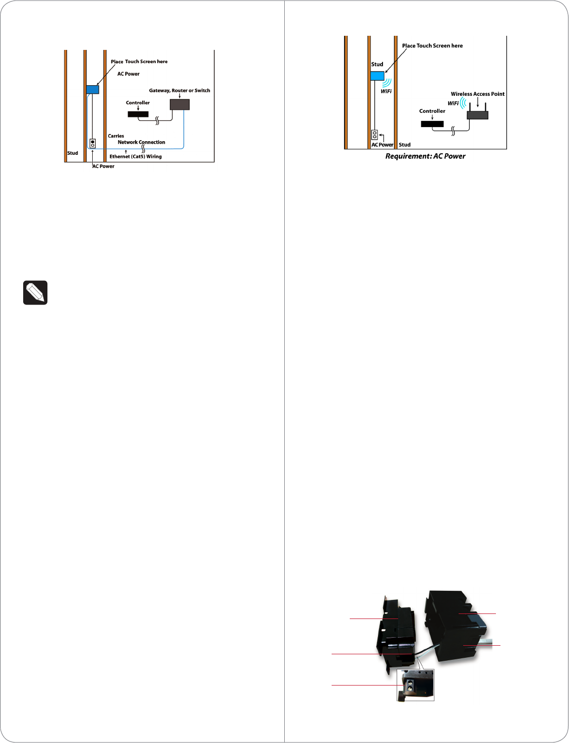
Figure 5. Ethernet - Requires a Connection to
Ethernet and AC Power
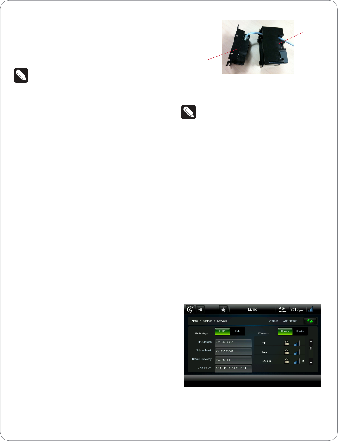
Option3:WiFiConnectionwithAC
Place the Touch Screen above a power source, for
example, an outlet. Ensure that you have WiFi in the
home (see Figure 6).
NOTES: (1) Video Intercom. Although this
device supports b/g/n, 802.11 b is not
supported for Video Intercom use. (2)
Wireless-N is recommended for Video
Intercom. See the Composer Pro User Guide
for details about the 7” In-Wall Touch Screen
with Camera properties.
WirelessNetworkLimitations
Many WiFi Access Points handle Multicasts
(WiFi simultaneously sent to multiple devices,
for example, when the 7” In-Wall Touch Screen
with Camera broadcasts video to all stations)
by slowing down transmission speed to the
1 Mb basic rate. This can cause overall WiFi
congestion in the WiFi network during the
broadcast. Video Intercom response times and
images may degrade at each device.
If a home requires a large number of WiFi
Video Intercom devices, ensure that you have
a robust WiFi network (possibly consisting of
multiple access points).
Figure 6. WiFi - Requires AC Power and WAP
Power Installation
Prepare the plastic power box for installation into the
back box by inserting either the Ethernet cable or the
AC power cable into the power box (see Figures 7
and 8), and then follow the instructions next.
ACPowerConnection
The steps below represent a typical U.S. installation.
1 Connect the wires to the AC power source for
the Touch Screen according to the national and
local electrical codes. Installation may require
alternative wires and the use of a terminal block.
2 Thread the power cable through the bottom back
hole of the back box to the terminal block (see
Figure 7).
3 Strip the black and white power wire ends to 1/4”
as necessary. Using a flathead screwdriver, loosen
the screws on the power box’s terminal block and
connect the power wires to each terminal (see
Figure 7).
4 Cap the ground wire from the wall if you are
using a plastic back box. Attach the ground wire
to the back box if using a metal back box.
Figure 7. AC Power Connection
5
Power Box Back Box
Power Cable
Terminal
Block
Connect
Wires
to Terminal
Block
5 Align and bend the wires carefully to fit them
inside the back box.
6 Align and carefully slide the power box into the
back box.
7 Secure the power box into the back box using
the screws provided.
NOTE: Overtightening the power box screws
could result in a poor connection between the
Touch Screen and the power box and could
also cause the Touch Screen to warp.
8 Align and slide the back of the Touch Screen into
the power box. The Touch Screen is magnetic
and should snap into place easily.
9 (Optional) To secure the Touch Screen inside the
power box, remove the tape covering the bottom
security pin (see Figure 10) before attaching the
Touch Screen to the power box.
PowerOverEthernet(PoE)Connection
Connect the PoE Injector to power and the network,
and then connect it to the power box.
The steps below describe how to install a Control4
PoE Injector.
1 Connect the Control4 PoE Injector to an AC
outlet using the power cord.
2 Connect one of the RJ-45 LAN ports on the
gateway/router/switch to the PoE Injector’s LAN
port using the RJ-45 Ethernet cable.
3 Connect the PoE Injector’s PWR LAN-OUT
port to the RJ-45 Ethernet cable that will be
connected to the Touch Screen.
4 Pull the Ethernet cable through the top back hole
of the back box to the Ethernet connector on the
top back of the power box, and then connect it
(see Figure 8).
5 Align and carefully slide the power box into the
back box until the Touch Screen is attached to
the power box.
Figure 8. Ethernet Connection
6 Secure the power box into the back box using
the screws provided.
NOTE: Overtightening the power box screws
could result in a poor connection between the
Touch Screen and the power box and could
also cause the Touch Screen to warp.
7 Align and slide the back of the Touch Screen into
the power box. The Touch Screen is magnetic
and should snap into place easily.
8 (Optional) To secure the Touch Screen inside the
power box, remove the tape covering the bottom
security pin (see Figure 10) before attaching the
Touch Screen to the power box.
Configuration
Configure for Wireless
(WiFi only) Connect to a WAP on the Touch Screen
(see Figure 9):
Figure 9. Wireless Configuration
1 After initialization, press and hold the large White
4in the center of the Touch Screen to enter the
configuration screen.
2 Press the Network button on the Touch Screen’s
6
Ethernet
Connection
Power Box
Back Box
configuration page. The network configuration
screen displays.
3 Under Wireless, select Enable. If you don’t see
the network you want, select Other.
4 At Network Name, select to add the SSID or
wireless network when the keyboard appears.
Select Done.
5 At Security, select None, WEP64, WEP128,
WPA, or WPA2.
6 At Password, type the password on the keyboard
that appears. Press Done.
7 Select Connect. Notice that the IP settings
change. The IP address is set to DHCP by default.
8 (Optional) If you need to set a static IP address
instead, complete the following steps:
a On the Network page, press Static.
b Select each box one at a time and type the
address: IP Address, Subnet Mask, Default
Gateway, Preferred DNS, and Alternate DNS.
c When the keyboard appears, type the
address, and then press Done.
9 Press OK to return to the Network page. You can
now connect to a Control4 Director running on a
Control4 device on the network.
10 Press OK.
Configure in Composer Pro
When the Touch Screen is physically installed and
appears on the home network, you can add and
configure it for the Control4 System using Composer
Pro. Choose theIn-Wall7”TouchScreenV2 driver in
Composer and add it to your project.
See the Composer Pro User Guide for information
about how to add and identify the Touch Screen to
the Control4 System.
Troubleshooting
Boot Up
When the device is booting up, it may take 30
seconds or longer before the Green LED turns on.
When it turns on, it blinks slowly for a time and then
turns o. After that, you will see an image on the
Touch Screen.
Restore to Factory Default
If the camera’s LED blinks on and o for more than
30 seconds, the device will need to be restored.
To access the Factory Restore switch, you’ll first need
to remove the Touch Screen.
NOTE: If there’s tape on the bottom of the
power box, simply lift the Touch Screen o
(see Steps 3 through 6). Remove the tape to
lock the Touch Screen in place. If there’s no
tape, the Touch Screen is locked into place. In
this case, follow the instructions below.
1 Locate the small hole underneath the Touch
Screen’s faceplate (see Figures 10 - 13).
Figure 10. Touch Screen Underside - Pin and Pinhole
2 Using a small unbent paper clip, insert the paper
clip straight up and into the small hole (about
1/4”) or as far as you can. There’s another small
hole inside the Touch Screen which the paper clip
needs to insert into also (see Figures 11 through
13). You may need to wiggle the paper clip a bit
to get it into the second small hole.
Figure 11. Locate Touch Screen Hole
7
Speaker Insert paper clip here to
remove Touch Screen
Security pin
Insert Paper Clip Here
Insert Paper Clip
Through this Hole
Too
Bottom of Touch Screen
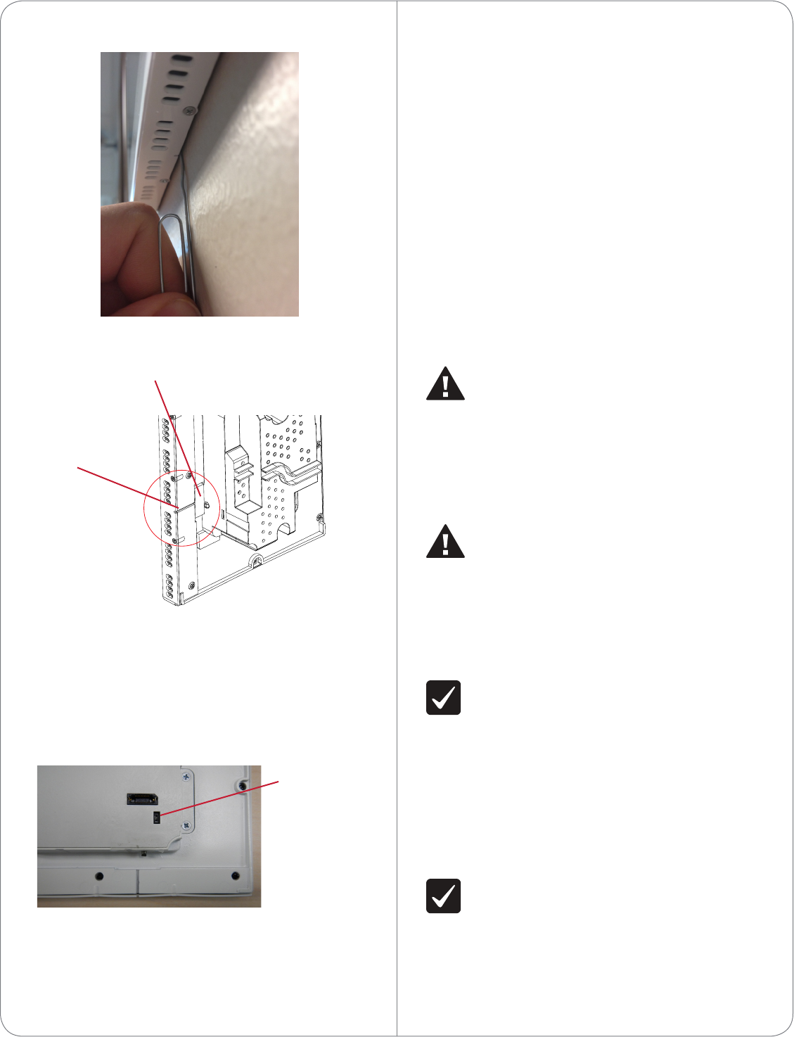
Figure 12. Insert Paper Clip Through Small Hole
Figure 13. Paper Clip Needs to Engage Release Plate
3 With both hands, tilt the bottom of the Touch
Screen out and gently remove the Touch Screen.
4 On the back of the Touch Screen locate the small
switch (see Figure 14).
Figure 14. Factory Restore Switch
5 Using the tip of a straight pin or paper clip,
change the position of the switch, for example, if
the switch is in the down position, push it to the
up position. The Touch Screen will then sense the
change on the next power up, and will initiate the
restore process.
6 When you are finished with the restore, reattach
the Touch Screen into the power box in the wall—
top first—and then snap the bottom of the Touch
Screen back into place.
7 The Touch Screen will reboot and the factory
default firmware image will be installed. All
settings will reset to the factory default settings.
See “LED Indicator” for information about how
the LED behaves during a factory restore.
8 After a restore, the Touch Screen will need to be
updated to the same image version of the project
(e.g., OS 2.2.2 or later).
Warnings/Considerations
WARNING! The Touch Screen must be
protected by an external circuit breaker or
a fuse rated at 6A maximum when used in
Europe.
AVERTISSEMENT! Pour réduire le risque du
feu ou de choc électrique, n’exposez pas cet
appareil à la pluie ou à l’humidité.
WARNING! Do not place the Touch Screen
near sources of heat or expose to direct
sunlight for an extended period of time.
AVERTISSEMENT! Ne placez pas l’unité
près des sources de chaleur ou exposition
pour diriger la lumière du soleil pendant une
période prolongée.
IMPORTANT! Do not use pens or sharp
objects to navigate or make selections on
the Touch Screen. To select an item or scroll
through a list, use your fingertip.
IMPORTANT! N’employez pas les stylos ou les
objets pointus pour diriger ou pour faire des
choix sur l’écran. Pour choisir un article ou un
rouleau par une liste, employez votre bout du
doigt.
IMPORTANT! Improper use or installation can
cause DAMAGE OF PROPERTY.
IMPORTANT! L’utilisation ou l’installation
inexacte peut causer DAMAGE DE
PROPRIÉTÉ.
8
Factory Restore
Switch
C4-7” TOUCH SCREEN IN WALL-V21:1 SCALE
Security plate
Pinhole
IMPORTANT! Using this product in a manner
other than outlined in this document voids
your warranty. Further, Control4 is NOT liable
for any damage incurred with the misuse of
this product. See “Warranty.”
IMPORTANT! Utilisant ce produit en quelque
sorte autre que décrit dans ce document vide
votre garantie. De plus, Control4 n’est pas
responsable d’aucun dommage encouru avec
l’abus de ce produit. Voyez que «Warranty.»
WARNING! Install in accordance with all
national, state, and local electrical
CODES.
AVERTISSEMENT! Installez selon tous les
national, état, et codes électriques locaux.
WARNING! This product generates heat. The
room must have adequate VENTILATION or
the ability to dissipate heat eectively.
AVERTISSEMENT! Ce produit produit de la
chaleur. La salle doit avoir à VENTILATION
proportionnée ou la capacité d’absorber la
chaleur ecacement.
WARNING! This product must be grounded in
accordance with the National Electrical Code
(NEC) requirements.
AVERTISSEMENT! Ce produit doit être fondu
selon les conditions électriques nationales de
code (NEC).
WARNING! Use this product only in dry
locations.
AVERTISSEMENT! Employez ce produit
seulement dans des endroits secs.
CAUTION! This product is for residential use
only.
ATTENTION! Ce produit est pour à l’usage
résidentiel ou commercial seulement.
MAGNET WARNING! Located within the
plastic enclosures of this product are strong
(rare earth) magnets that are used to
attach the face plate to the electrical box. If
someone handling or using the product has a
pacemaker, defibrillator, or similar electronic
device used for health purposes, avoid close
proximity (closer than 20 inches) to the
9
product until you consult your physician.
Magnetic fields can cause damage to
magnetic storage media (for example, credit
cards, video tapes, computer hard drives, etc).
Keep all magnets at least 20 inches away from
all types of magnetic media. Certain electronic
devices are sensitive to magnetic
FIELDS and may be damaged permanently or
temporarily disabled if exposed to a magnetic
field that is too strong. Consult the owner’s
manuals of your electronic devices for further
information. INGESTED magnets can cause
serious injuries and may result in death. If
magnets have been ingested (or you suspect
they might have been), seek competent
medical attention immediately.
AVERTISSEMENT! Aimants! Dans l’emballage
en plastique de ce produit sont inclus des
aimants très puissants utilisés pour attacher
les plaques de surface aux boites électriques.
Si quelqu’un, manipulant ou utilisant ce produit
est muni d’un pacemaker, défibrillateur ou
autre dispositif d’ordre médical, il doit éviter
de se trouver à proximité (moins de 20
pouces) de ce produit avant d’avoir consulté
son médecin. Les champs magnétiques des
aimants peuvent endommager le stockage
d’information d’ordre magnétique (ex :
cartes de crédit, bandes vidéo, disques durs
d’ordinateur, etc.) Gardez tous les aimants au
moins à 20 pouces de distance de tout type
de stockage d’information d’ordre magnétique.
Certains dispositifs électroniques sont
sensibles aux champs magnétiques et peuvent
être endommagés de façon permanente
ou être désactivés si ils sont exposés à un
champs magnétique trop puissant. Pour plus
d’information, consultez le manuel d’utilisateur
propre à votre pièce électronique.
SI avalés, les aimants peuvent causer des
blessures graves et aussi causer la mort. Si
des aimants ont été avalés (ou vous doutez
qu’ils ont pu l’être) obtenez les soins médicaux
de personnes compétentes immédiatement.

©2012 Control4. All rights reserved. Control4, the Control4 logo, the Control4 iQ logo and the Control4 certified logo are registered trademarks or trademarks of Control4 Corporation in
the United States and/or other countries. All other names and brands may be claimed as the property of their respective owners.
control4.com | ™
Third-PartyTrademarks
Libertas
Libertas Firmware copyright statement for Touch Screens 6/26/09
Copyright (c) 2006, One Laptop per Child and Marvell Corporation.
All rights reserved.
Redistribution. Redistribution and use in binary form, without modification, are
permitted provided that the following conditions are met:
* Redistributions must reproduce the above copyright notice and the following
disclaimer in the documentation and/or other materials provided with the
distribution.
* Neither the name of Marvell Corporation nor the names of its suppliers may
be used to endorse or promote products derived from this software without
specific prior written permission.
* No reverse engineering, decompilation, or disassembly of this software is
permitted.
* You may not use or attempt to use this software in conjunction with any
product that is oered by a third party as a replacement, substitute or
alternative to a Marvell Product where a Marvell Product is defined as a
proprietary wireless LAN embedded client solution of Marvell or a Marvell
Aliate.
DISCLAIMER. THIS SOFTWARE IS PROVIDED BY THE COPYRIGHT
HOLDERS AND CONTRIBUTORS “AS IS” AND ANY EXPRESS OR IMPLIED
WARRANTIES, INCLUDING, BUT NOT LIMITED TO, THE IMPLIED WARRANTIES
OF MERCHANTABILITY AND FITNESS FOR A PARTICULAR PURPOSE
ARE DISCLAIMED. IN NO EVENT SHALL THE COPYRIGHT OWNER OR
CONTRIBUTORS BE LIABLE FOR ANY DIRECT, INDIRECT, INCIDENTAL,
SPECIAL, EXEMPLARY, OR CONSEQUENTIAL DAMAGES (INCLUDING, BUT
NOT LIMITED TO, PROCUREMENT OF SUBSTITUTE GOODS OR SERVICES;
LOSS OF USE, DATA, OR PROFITS; OR BUSINESS INTERRUPTION) HOWEVER
CAUSED AND ON ANY THEORY OF LIABILITY, WHETHER IN CONTRACT,
STRICT LIABILITY, OR TORT (INCLUDING NEGLIGENCE OR OTHERWISE)
ARISING IN ANY WAY OUT OF THE USE OF THIS SOFTWARE, EVEN IF
ADVISED OF THE POSSIBILITY OF SUCH DAMAGE.
GNU
GNU GENERAL PUBLIC LICENSE TERMS AND CONDITIONS FOR COPYING,
DISTRIBUTION AND MODIFICATION (Section 3.b.)
You may copy and distribute the Program (or a work based on it, under Section
2) in object code or executable form under the terms of Sections 1 and 2 above
provided that you also do one of the following:
Accompany it with a written oer, valid for at least three years, to give any
third party, for a charge no more than your cost of physically performing
source distribution, a complete machine-readable copy of the corresponding
source code, to be distributed under the terms of Sections 1 and 2 on a medium
customarily used for software interchange.
The complete text for this license is available on the Control4 website at: http://
www.control4.com.
Regulatory/Safety/Other
Information
To review regulatory information for your particular Control4
products, see the information located on the Control4 website at:
http://www.control4.com/regulatory/.
Patent Information
Protected under U.S. Patents 7,335,845, 7,106,261 and licensed under
U.S. Patents 5,905,442 and 5,982,103
Warranty
Limited 2-year Warranty. Refer to http://www.control4.com/warranty.
10
About this Document
Part Number: 200-00288, Rev B, 6/11/2012

Regulatory Compliance & Safety Information for Contol4 Model C4-TW7C0-XX.
Electrical Safety Advisory
Important Safety Information
Read the safety instructions before using this product.
1. Read these instructions.
2. Keep these instructions.
3. Heed all warnings.
4. Follow all instructions.
5. Do not use this apparatus near water.
6. Clean only with dry cloth.
7. Do not block any ventilation openings. Install in accordance with the manufacturer’s
instructions.
8. Do not install near any heat sources such as radiators, heat registers, stoves, or other
apparatus (including amplifiers) that produce heat.
9. Do not defeat the safety purpose of the polarized or grounding-type plug. A polarized
plug has two blades with one wider than the other. A grounding type plug has two blades
and a third grounding prong. The wide blade or the third prong is provided for your safety.
If the provided plug does not fit into your outlet, consult an electrician for replacement of
the obsolete outlet.
10. Protect the power cord from being walked on or pinched particularly at plugs,
convenience receptacles, and the point where they exit from the apparatus.
11. Only use attachments/accessories specified by the manufacturer.
12. Use only with the cart, stand, tripod, bracket, or table specified by the manufacturer, or
sold with the apparatus. When a cart is used, use caution when moving the
cart/apparatus combination to avoid injury from tip-over.
13. Unplug this apparatus during lightning storms or when unused for long periods of time.
This equipment uses AC power which can be subjected to electrical surges, typically
lightning transients which are very destructive to customer terminal equipment connected
to AC power sources. The warranty for this equipment does not cover damage caused
by electrical surge or lightning transients. To reduce the risk of this equipment becoming
damaged it is suggested that the customer consider installing a surge arrestor.
14. Refer all servicing to qualified service personnel. Servicing is required when the
apparatus has been damaged in any way, such as power-supply cord or plug is
damaged, liquid has been spilled or objects have fallen into the apparatus, the apparatus
has been exposed to rain or moisture, does not operate normally, or has been dropped.
15. Use the mains plug to disconnect the apparatus from the AC mains. The mains plug shall
remain readily operable.
16. To completely disconnect unit power from the AC mains, disconnect the unit’s power cord
from the mains socket. To reconnect power, plug the unit’s power cord into the mains
socket following all safety instructions and guidelines.
17. CAUTION: As with all batteries, there is a risk of explosion or personal injury if the
battery is replaced by an incorrect type. Dispose of used battery according to the
instructions of the battery manufacturer and applicable environmental guidelines. Do not
open, puncture or incinerate the battery, or expose it to conducting materials, moisture,
liquid, fire or heat above 54° C or 130° F.
18. Never push objects of any kind into this product through cabinet slots as they may touch
dangerous voltage points or short out parts that could result in fire or electric shock.
19. This product can interfere with electrical equipment such as tape recorders, TV sets,
radios, computers and microwave ovens if placed in close proximity.
The lightning flash and arrow head within the triangle is a warning sign alerting
you of dangerous voltage inside the product
Caution: To reduce the risk of electric shock, do not remove cover (or back). No
user serviceable parts inside. Refer servicing to qualified service personnel.
The exclamation point within the triangle is a warning sign alerting you of
important instructions accompanying the product.
See marking on bottom / back of product
Warning!: To reduce the risk of electrical shock, do not expose this
apparatus to rain or moisture
AVERTISSEMENT! Pour réduire le risque de choc électrique,
n'exposez pas cet appareil à la pluie ou à l'humidité.
WARNUNG! Um das Risiko des elektrischen Schlages zu verringern,
setzen Sie diesen Apparat nicht Regen oder Feuchtigkeit aus.
Save these instructions
Compliance of this equipment is confirmed by the following label that is placed on the equipment:
USA & Canada Compliance
FCC Part 15, Subpart B / ICES-003Unintentional Emissions Interference Statement
This equipment has been tested and found to comply with the limits for a Class B digital device,
pursuant to Part 15 of the FCC rules and Industry Canada ICES-003. These limits are designed
to provide reasonable protection against harmful interference when the equipment is operated in
a residential installation. This equipment generates uses and can radiate radio frequency energy
and, if not installed and used in accordance with the instructions, may cause harmful interference
to radio communications. However, there is no guarantee that interference will not occur in a
particular installation. If this equipment does cause harmful interference to radio or television
reception, which can be determined by turning the equipment off and on, the user is encouraged
to try to correct the interference by one or more of the following measures:

Reorient or relocate the receiving antenna.
Increase the separation between the equipment and receiver.
Connect the equipment into an outlet on a circuit different from that to which the receiver
is connected.
Consult the dealer or an experienced radio/TV technician for help.
This device complies with part 15 of the FCC rules and Industry Canada ICES-003. Operation is
subject to the following two conditions: (1) This device may not cause harmful interference, and
(2) this device must accept any interference received, including interference that may cause
undesired operation.
Le présent appareil est conforme aux CNR d’Industrie Canada applicables aux appareils radio
exempts de licence. L’exploitation est autorisée aux deux conditions suivantes : (1) l’appareil ne
doit pas produire de brouillage, et (2) l’utilisateur de l’appareil doit accepter tout brouillage
radioélectrique subi, même si le brouillage est susceptible d’en compromettre le fonctionnement.
IMPORTANT! Any changes or modifications not expressly approved by the party responsible for
compliance could void the user’s authority to operate this equipment.
IMPORTANT! Tous les changements ou modifications pas expressément approuvés par la partie
responsable de la conformité ont pu vider l’autorité de l’utilisateur pour actionner cet équipement.
Ferrite clamp installation. When installing a Control4® 7” In-Wall Touch Screen, also install the
enclosed ferrite clamp as described in this document.
Ethernet cable. Install the ferrite clamp on the Ethernet cable no farther than 6 inches from the
Ethernet jack.
Compliance of this equipment is confirmed by the following label that is placed on the equipment:
FCC Part 15, Subpart C / RSS-210 Intentional Emissions Interference Statement
Compliance of this equipment is confirmed by the following certification numbers that are placed
on the equipment:
Notice: The term “FCC ID:” and “IC” before the certification number signifies that FCC and
Industry Canada technical specifications were met.
FCC ID: R33C4TW7C0
IC: 7848A-C4TW7C0
This equipment must be installed by qualified professionals or contractors in accordance with
FCC Part 15.203 & IC RSS-210, Antenna Requirements. Do not use any antenna other than the
one provided with the unit.

RF Radiation Exposure Statement
This equipment complies with the FCC/IC radiation exposure limits set fourth for portable
transmitting devices operation in an uncontrolled environment. End users must follow the specific
operating instructions to satisfy RF exposure compliance.
The equipment should only be used or installed at locations where there is normally at
least a 20cm separation between the antenna and all persons.
This transmitter must not be co-located or operation in conjunction with any other
antenna or transmitter.
Any changes or modifications not expressly approved by the party responsible for
compliance could void the user’s authority to operate this equipment.
European Compliance
Conformity of the equipment with the guidelines below is attested by the application of the CE
mark.
CE Declaration of Conformity
Manufacturer’s Name: CONTROL4 CORPORATION
Manufacturer’s Address: 11734 S. ELECTION ROAD SUITE 200
SALT LAKE CITY
UT 84020 USA
EU Representative Name: CONTROL4 EMEA LIMITED
EU Representative Address: UNIT3, GREEN PARK BUSINESS CENTRE
SULTON-ON-THE FOREST
YORK YO61 IET, UNITED KINGDOM
Product Name(s): Touch Screen
Brand: Contol4
Model(s): C4-TW7C0-XX
Product Standard(s) to which Conformity of the Council Directive(s) is declared:
EMC - 2004/108/EC “Electromagnetic Compatibility (EMC) Directive”:
(Emissions) EN 55022:2010, (Immunity) EN 55024:1998, EN 301 489-1:2008, EN 301 489-
17:2009, EN 61000-3-2:2004 & EN 61000-3-3:2002
Safety – 206/95/EC “Low Voltage Directive (LVD)”:
EN 60950-1:2006 (2nd Edition) .
Telecom & Radio - 1999/5/EC Radio equipment and Telecommunications Terminal
Equipment (R&TTE) Directive:
EN 300 328 V1.7.1 (2006-10)
RoHS - 2002/95/EC Restriction of the Use of certain Hazardous Substances in Electrical
and Electronic Equipment (EEE) & WEEE - 2002/96/EC Waste of Electrical and Electronic
Equipment (EEE).

We, the undersigned, hereby declare that the equipment specified above conforms to the above
directives and standards. Date of Issue: June 5, 2012
Legal Representative
Signature
Roger Midgley
Sr. Regulatory Compliance Engineer
National Restrictions
This product may be used in all EU countries (and other countries following the EU directive
1999/5/EC) without any limitation except for the countries mentioned below:
Ce produit peut être utilisé dans tous les pays de l'UE (et dans tous les pays ayant transposés la
directive 1999/5/CE) sans aucune limitation, excepté pour les pays mentionnés ci-dessous:
Questo prodotto è utilizzabile in tutte i paesi EU (ed in tutti gli altri paesi che seguono le direttive
EU 1999/5/EC) senza nessuna limitazione, eccetto per i paesii menzionati di seguito:
Das Produkt kann in allen EU Staaten ohne Einschränkungen eingesetzt werden (sowie in
anderen Staaten die der EU Direktive 1999/5/CE folgen) mit Außnahme der folgenden
aufgeführten Staaten:
France
In case the product is used outdoors, the output power is restricted in some parts of the band.
See Table 1 below or check http://www.arcep.fr/ for more details.
Dans la cas d'une utilisation en extérieur, la puissance de sortie est limitée pour certaines parties
de la bande. Voir la table ci-dessous ou visitez http://www.arcep.fr/ pour de plus amples details
Table 1 Applicable Power Levels in France
Location Frequency Range (MHz) Power (EIRP)
Indoor (No restrictions) 2400-2483.5 100 mW (20 dBm)
Outdoor 2400-2454
2454-2483.5 100 mW (20 dBm)
10 mW (10 dBm)
Recycling
Control4 understands that a commitment to the environment is essential for a health life and
sustainable growth for future generations. We are committed to supporting the environmental
standards, laws, and directives that have been put in place by various communities and countries
that deal with concerns for the environment. This commitment is represented by combining
technological innovation with sound environmental business decisions.
WEEE Compliance
Control4 is committed to meeting all requirements of the Waste Electrical and Electronic
Equipment (WEEE) directive (2002/96/EC). The WEEE directive requires the manufacturers of
electrical and electronic equipment who sell in EU countries: (1) label their equipment to notify
customers that it needs to be recycled, and (2) provide a way for their products to be
appropriately disposed of or recycled at the end of their product lifespan. For collection or
recycling of Control4 products, please contact your local Control4 representative or dealer.
Australia / New Zealand Compliance
Compliance of this equipment is confirmed by the following label that is placed on the equipment:
About this Document
Copyright © 2012 Control4 Corporation. All rights reserved. Control4 and the Control4 logo are
registered trademarks or trademarks of Control4 Corporation in the United States and/or other countries.
Part Number 200-00292 Rev A, 6/5/2012