Snap One KPZ10B11 Wireless LCD Keypad Model KPZ-10B1-(Color) User Manual LCDKeypad IG
Control4 Wireless LCD Keypad Model KPZ-10B1-(Color) LCDKeypad IG
Snap One >
Exhibit 8
Wireless
LCD Keypad
Installation
Guide
Supported Models
KPZ-10B1-W White LCD Keypad
KPZ-10B1-B Black LCD Keypad
KPZ-10B1-A Almond LCD Keypad
Graphical Symbols in this Guide
The following symbols and their descriptions draw your attention to safe
practices and additional information that can help you avoid injury, death, or
loss of material or time.
WARNING! This indicates a potentially hazardous situation that, if not avoided,
may result in death or serious injury. DO NOT IGNORE A WARNING!
CAUTION! This indicates a potentially hazardous situation that, if not avoided,
may result in minor or moderate injury. DO NOT IGNORE A CAUTION!
IMPORTANT! This indicates information that will help you avoid damage to
your equipment, loss of materials, or loss of time. PAY ATTENTION TO
THESE IMPORTANT STATEMENTS!
NOTE: This indicates a note on related information about the current topic.
TIP: This indicates a tip that might save you time or effort.
Important Safety Instructions
1. Read these instructions.
2. Keep these instructions.
3. Heed all warnings.
4. Follow all instructions.
5. Do not use this apparatus near water.
6. Clean only with dry cloth.
7. Install in accordance with the manufacturer’s instructions.
8. Do not install near any heat sources such as radiators, heat registers, stoves, or other
apparatus (including amplifiers) that produce heat.
9. Protect the power cords, if applicable, from being walked on or pinched particularly at
plugs, convenience receptacles, and the point where they exit from the apparatus.
10. Only use attachments/accessories specified by the manufacturer.
11. If applicable, unplug this apparatus during lightning storms or when unused for long
periods of time.
12. Refer all servicing to qualified service personnel. Servicing is required when the appa-
ratus has been damaged in any way, such as power-supply cord or plug is damaged,
liquid has been spilled or objects have fallen into the apparatus, the apparatus has
been exposed to rain or moisture, does not operate normally, or has been dropped.
WARNING! To reduce the risk of fire or electrical shock, do not expose this
apparatus to rain or moisture.
WARNING! To avoid bodily harm, always contact a Control4-authorized reseller
for assistance if any repair or adjustment is required.
WARNING! Improper use or installation can cause LOSS/DAMAGE OF
PROPERTY.
CAUTION! Do not place unit near sources of heat or expose to direct sunlight
on the screen. Store in a cool and dry place.
General Description
An essential component in every home control system is a navigation device
that allows users to communicate with the Control4 system. Along with the
Wireless LCD Keypad, Control4 offers a variety of navigation options for every
room, including the System Remote Control, the On-screen (television), the
Mini Touch Screen, and the 10.5” Wireless Touch Screen, etc.
NOTE: For a complete list of Control4 devices, see “Products” at http://
www.Control4.com
The LCD Keypad offers complete system control in an elegant, compact
design. It is equipped with a backlit, interactive LCD screen that provides status
information and feedback.
The LCD Keypad uses ZigBee IEEE 802.15.4 wireless technology for
communication to a Control4 Controller, such as the a Home Theater Controller
or a Media Controller.
It has eight navigation buttons, an intuitive Select Dial, and a unique
programmable shortcut button.
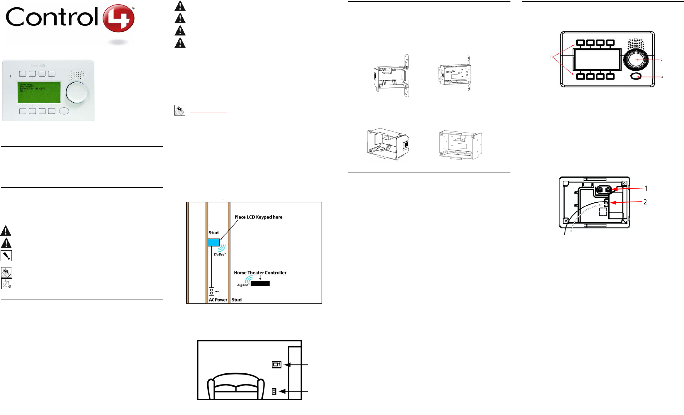
It gets its power from an AC power source close to the LCD Keypad installation
location. This power source requires both hot and neutral connections. See
Figure 1.
FIGURE 1. LCD Keypad - Requires AC power to LCD Keypad
Placement: Place at a convenient location comfortable for users to view
displays and choose menu options, typically at eye level , (approximately 57 to
61 inches from the floor) and near the entrance of a room.
Wall Box Kit Options
There are four wall-box options to install the LCD Keypad. Metal and plastic
wall boxes are available in new or retrofit versions. The following diagrams
show the available wall-mounting kits.
FIGURE 2. Mini Touch Screen/LCD Keypad Wall Box Kits - New Construction
FIGURE 3. Mini Touch Screen/LCD Keypad Wall Box Kit - Retrofit (includes
wall-box template)
What’s in the Box
Carefully unpack the contents from the box and make sure the following items
were included. If any item is missing or damaged, please contact your
Control4-authorized reseller immediately.
•Control4 LCD Keypad
•Two sheet-metal screws (1/2-inch) for attachment to a plastic wall box.
(Metal wall boxes require machine screws. These screws are included
with the Metal Wall Box Kit.)
•Three wire caps
•Warranty card
•LCD Keypad Installation Guide (this document)
•LCD Keypad User Guide
Requirements
•Home Theater Controller or Media Controller fully installed and config-
ured with a Control4 project.
•Control4 Mini Touch Screen/LCD Keypad custom wall-box kit. See
“Wall Box Kit Options.”
•Access to in-wall AC power source. (A neutral connection is required.)
•14 AWG electrical wire that is long enough to pull between LCD Key-
pad and power source.
Front and Rear Panel Descriptions
Front View
1. User Control Buttons (soft keys): For navigation and control of the
Control4 system.
2. Select Dial: For identifying the device during initial setup. Once setup is
complete, for scrolling through displays.
3. Shortcut Button: For custom programming to initiate an action or
sequence of actions.
4. Front Dimension: 6 1/2” (W) x 4 3/8” (H) x 1/5-2/5” (D)
5. Software: LCD Navigator (pre-installed)
6. Display: 3” viewing area FSTN LCD, 240x120 pixels, Grey on white with
white LED backlight
Back View
1. Power Supply: 100-240 VAC 60150 Hz (less than 6W)
2. AC Wires: For connecting the black (hot) and white (neutral) wires on the
back to the hot and neutral wires from the wall.
3. Power Consumption: 240x120
4. In-Wall Dimension: 5 7/8” (W) x 3 5/8” (H) x 1 1/2” (D)
5. Network Support: ZigBee IEEE 802.15.4
LCD Keypad
AC Outlet
Plastic model # AC-NWB3.8-G Metal model # AC-NWB3.8-M
Plastic model # AC-RWB3.8-G Metal model # AC-RWB3.8-M
Installation
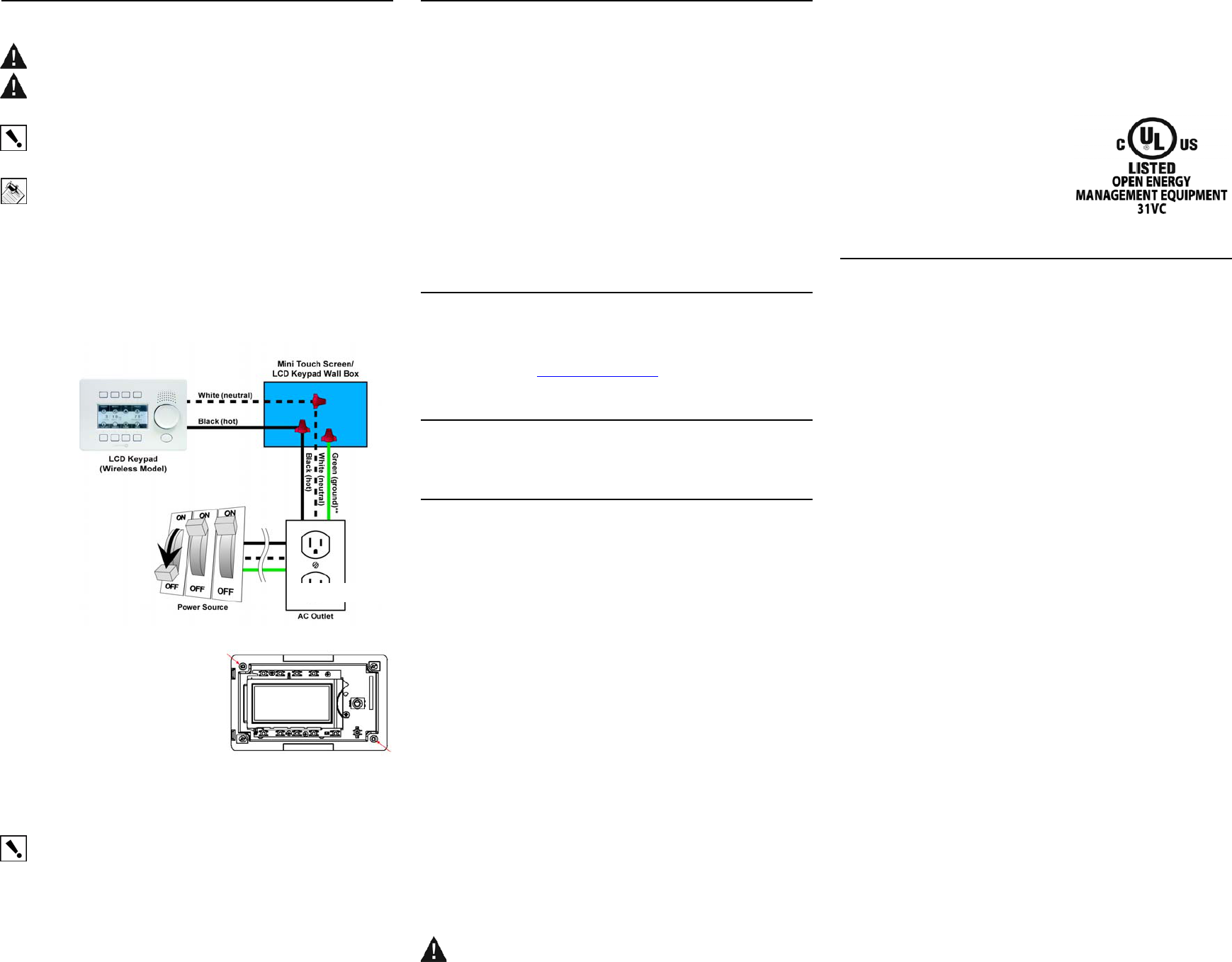
WARNING! For the circuit on which you will be working to install the LCD
Keypad, switch off the circuit breaker or remove the fuse.
WARNING! For new or retrofit, when cutting the opening for the wallbox, DO
NOT cut the opening too large. Be conservative and cautiously enlarge it as
needed because there is not as much overhang on the faceplate of the LCD
Keypad as you are accustomed to with standard switch and outlet plates.
IMPORTANT! Before you can complete the installation instructions for the LCD
Keypad, you must have a Control4 Mini Touch Screen\LCD Keypad Wallbox
installed according to the documentation provided in the wallbox kit. Ensure that a
14 AWG electrical wire is pulled between the power source and the wall box.
NOTE: The table top LCD Keypad models are sold assembled. These
installation instructions do not apply
1 Connect the AC wires from the back of the LCD Keypad to the wires from
the wall.
a. Connect the black (hot) and white (neutral) wires from the back of
the LCD Keypad to the hot and neutral wires from the wall.
b. Cap the ground wire from the wall if you are using a plastic wall box.
If you are using a metal wall box, attach the ground wire to the box at
the location designated by the ground symbol.
FIGURE 4. LCD Keypad Wiring for Plastic Wall Box.
2 With the screws provided, attach the
LCD Keypad base at the top-left and
bottom-right corners of the wall box
(as shown).
3 Hook the tabs on the left underside of
the faceplate onto the lip of the base
on the left-hand side. Then close the
faceplate over the top of the base
from left to right, feeding the Select
Dial post through the corresponding hole in the faceplate.
4 Install the washer and the nut to hold the faceplate in place.
IMPORTANT! Tighten the nut by hand. Do not overtighten. Excessive force will
permanently damage the rotary device and void the warranty.
5 Install the Select Dial on the post.
6 Now that your LCD Keypad is physically installed and appearing on the
home network, you can add it to the Control4 System using the Composer
software (available for your PC). See Composer online help for
information on how to add the LCD Keypad and other devices to the
Control4 System.
Troubleshooting
If you experience operational problems with the Control4 LCD Keypad, check
the following list for system troubleshooting. If problems persist, contact your
authorized Control4 dealer for technical support.
System Operation Problems Question and Answers
Question: What if there is a problem connecting?
Answer: Make sure that the LCD Keypad is added to your project and that the
device is identified.
Question: What if the LCD Keypad is damaged?
Answer: Contact your Control4-authorized reseller.
Question: What if there is something wrong with hardware or ZigBee
radio?
Answer: Contact your Control4-authorized reseller.
Additional Resources
The following resources are available to provide you with additional support:
•Your authorized Control4 reseller
•Control4 Web Site: http://www.control4.com
•Composer online help
Warranty
See LCD Keypad User Guide for warranty information.
Regulatory Compliance
This product complies with standards established by the following regulatory
bodies:
Federal Communications Commission (FCC)
Industry Canada
Underwriters Laboratories Inc. (UL)
FCC Interference Statement
This equipment has been tested and found to comply with the limits for a Class
B digital device, pursuant to Part 15 of the FCC Rules. These limits are
designed to provide reasonable protection against harmful interference in a
residential installation. This equipment generates, uses, and can radiate radio
frequency energy and, if not installed and used in accordance with the
instructions, may cause harmful interference to radio communications.
However, there is no guarantee that interference will not occur in a particular
installation. If this equipment does cause harmful interference to radio or
television reception, which can be determined by turning the equipment off and
on, the user is encouraged to try to correct the interference by one or more of
the following measures:
•Reorient or relocate the receiving antenna.
•Increase the separation between the equipment and receiver.
•Connect the equipment into an outlet on a circuit different from that to
which the receiver is connected.
•Consult the dealer or an experienced radio/TV technician for help.
FCC Caution
IMPORTANT! Any changes or modifications not expressly approved by the
party responsible for compliance could void the user's authority to operate the
equipment.
This device complies with Part 15 of the FCC Rules. Operation is subject to the
following two conditions: (1) This device may not cause harmful interference,
and (2) this device must accept any interference received, including
interference that may cause undesired operation.
Industry Canada Statement
This Class B digital apparatus complies with Canada ICES-003.
Cet appareil numérique de la classe B est conforme à la norme NMB-003 du
Canada.
Underwriters Laboratories Inc. (UL)
This product has been tested by UL and has
been found to be in compliance with:
UL 916:1998: Standard for Energy
Management Equipment
CAN/CSA-C22.2 No. 205-FM1983
About this Document
United States Patents Pending. Copyright © 2005 Control4 Corporation.
Control4 and the Control4 logo are registered trademarks of Control4
Corporation. All trademarks are properties of their respective owners.
Part Number: 21-0120 Rev A Draft 2