Snap One KPZ6B1 Wireless Keypad Model KPZ-6B1 User Manual Wireless6 ButtonKeypad
Control4 Wireless Keypad Model KPZ-6B1 Wireless6 ButtonKeypad
Snap One >
Exhibit 8
Control4 Wireless 6-Button Keypad Installation and User Guide 1
Wireless 6-Button
Keypad Installation
and User Guide
Supported Models, Features, and Fixtures
This installation guide covers these 6-button keypad models:
The Control4 Wireless 6-Button Keypad can be configured as a peer-
to-peer device or as part of the Control4 network. It can be
programmed to do any supported network event (such as controlling
a group of lights, a music zone, or a security system) or can simply be
used to replace 3 light switches. It installs in a standard wall box using
typical wiring standards and gets power from a nearby power outlet or
light switch. It communicates to the system using a wireless
connection and features a tri-color LED for system feedback. It
supports lighting fixtures with the following load requirements:
•120 Volt incandescent (all types)
•120 Volt halogen (all types)
•120 Volt magnetic low voltage
(all types with 70 percent or greater load factor)
•120 Volt electronic low voltage (dimmable only)
•120 Volt fluorescent light fixtures (dimmable only)
Installation Instructions
Ensure that the location and intended use meet the
following criteria:
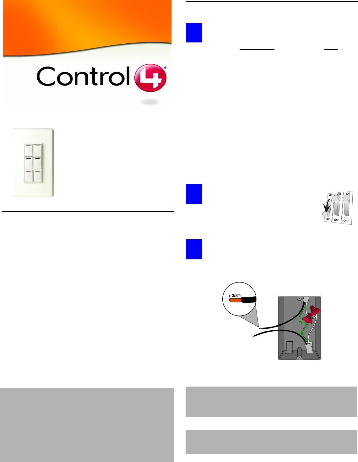
To avoid injury or death, turn OFF local
electrical power. To turn off the power,
either flip the circuit breaker or remove fuse
from fuse box. To ensure the wires do NOT
have power running to them, use an
inductive voltage detector.
Prepare and identify all wires. Identify the wires in your
wall box. Straighten the wire ends. With a wire cutter, cut off
the bare wire just below the plastic insulation on all wires.
Use a wire stripper to strip off about 3/8-inch of the
insulation.
LDZ-101-W Wireless 6-Button Keypad (802.15.4)
LDZ-101-B Wireless 6-Button Keypad (802.15.4)
LDZ-101-A Wireless 6-Button Keypad (802.15.4)
WARNING! To reduce the risk of serious injury or death, turn all
power OFF before installing this product. Using this
product in a manner other than outlined in this
document voids your warranty. Further, Control4 is
NOT liable for any damage incurred with the misuse of
this product. See “Limited 1 Year Warranty” on page 4.
This product generates heat. The room must have
adequate ventilation or heat dissipation ability. Do
NOT use this device to control a device with a non-
dimmable load. You should only use it with devices
that have dimmable feature support.
DO (OK, Normal) DON’T
•Install in accordance with all
national and local electrical
codes.
•Wall box size required depends
on your wiring. The 6-button key-
pad alone needs a depth of 2.5
inches. To calculate the total
depth required, add 2.5 inches to
the amount of space recom-
mended in the NCC Code for
your configuration.
•The range and performance of
the control system is highly
dependent on the following:
• Distance between devices
• Layout of the home
• Walls separating devices
• Electrical equipment
located near devices
•If installing a
multi-unit 6-but-
ton keypad, Do
NOT continue
until you have
read “Multi-Unit
Installations” on
page 2.
•Do NOT use
where total watt-
age is under 25
watts.
•Do NOT exceed
maximum load
rating of dimmer
(which is 1000W
for a single unit,
if both side tabs
are in tact).
IMPORTANT: The National Electric Code (NEC) requires 6 inches of
extended wire from the wall box. If your wiring does
not meet this requirement, you will not meet code. Do
NOT cut wire shorter than 6 inches.
IMPORTANT: When installing this product in a commercial
application or metal wall box, you might need to
ground it to the wall box.
1
2
3
Control4 Wireless 6-Button Keypad Installation and User Guide 2
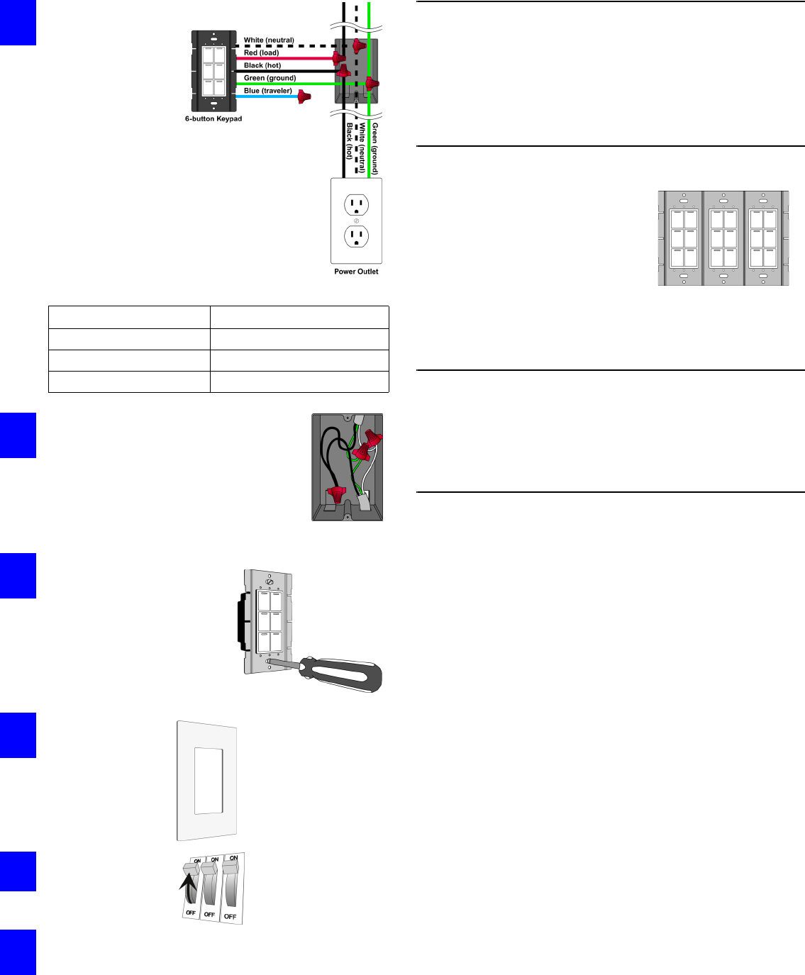
Connect the 6-
button keypad wires
to the wall box
wires using wire
nuts. The wall box
wires can differ
depending upon how
it was wired by your
electrician.
To wire the 6-button
keypad for a Control4
single-switch
environment with the
power coming from a
nearby power outlet
or light switch,
connect and cap with
a wire nut the wires
indicated in the table.
.
Fit wires back into the wall box. Bend the
wires in a zigzag pattern so that they easily
fold into the wall box. Push the 6-button
keypad into place. Adjust the 6-button
keypad so that it is perpendicular to the
floor. Tighten the two screws that hold it in
position in the wall box.
Align 6-button keypad to wall
box and fasten with screws,
unless you are using a Decora
screw-on-style wall plate. If
you are using a screw-on-style
wall plate, before fastening with
screws, you must first align the
wall plate with the 6-button
keypad and the wall box.
If you are using
the Control4
snap-on- style
wall plate, snap it
over the 6-button
keypad now.
Turn ON power at
circuit breaker or
replace fuse from
fuse box.
Test the see if it is working properly.
To operate and configure this 6-button keypad as a stand-
alone device, refer to the documentation that shipped with
your Control4 controller. Refer to information on configuring
or setting up lighting.
Troubleshooting
If light does not turn on:
•Ensure light bulb is not burned out.
•Ensure light bulb is screwed in tightly.
•Ensure circuit breaker is not turned OFF or tripped.
•Check for proper wiring.
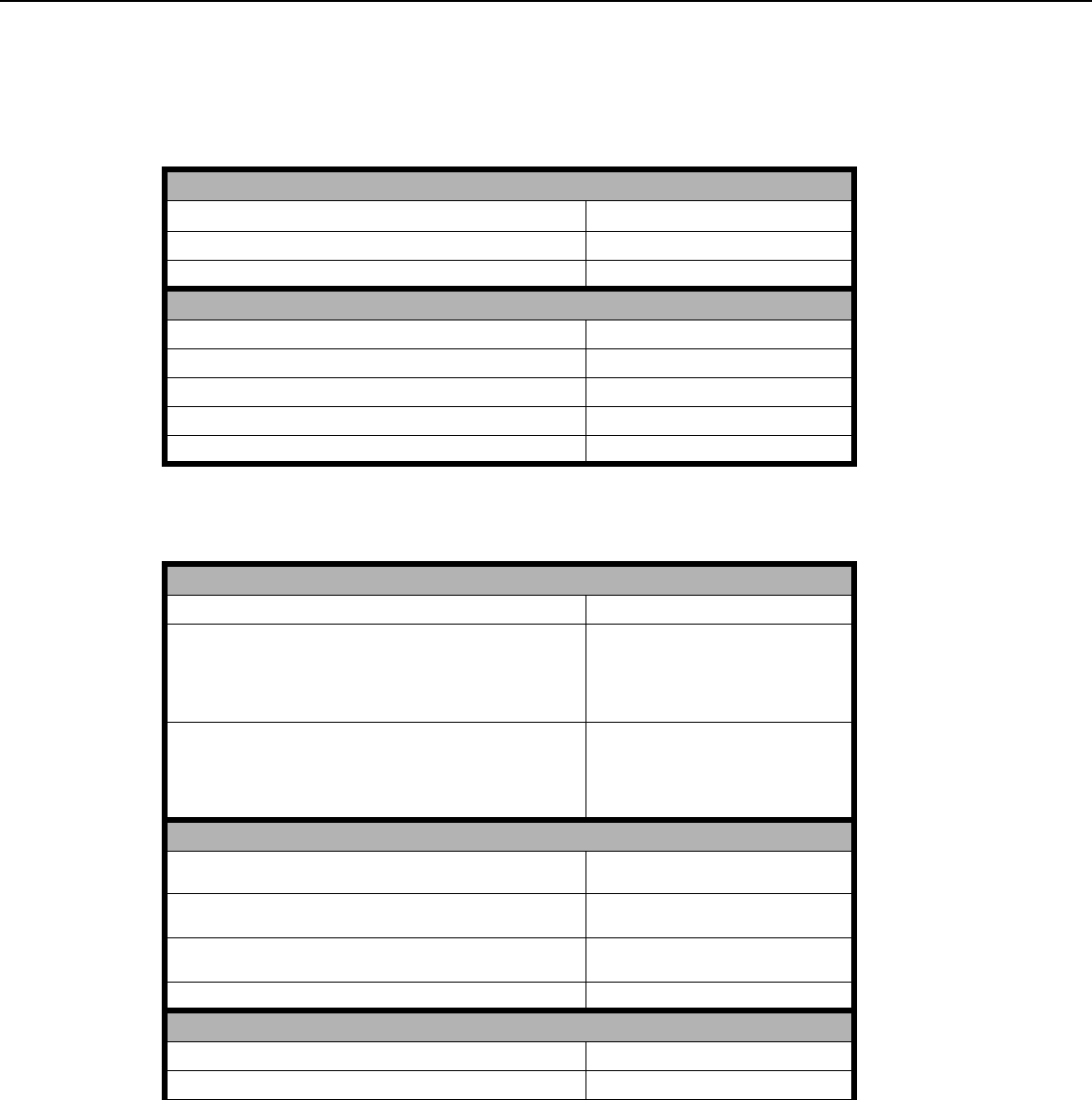
Multi-Unit Installations
Multi-unit installations allow you to install
one stand-alone 6-button keypad next to
another in the same wall box. Multi-unit
keypads ship pre-connected. DO NOT
remove side tabs from outer sides.They
help to regulate the capacity.
•With both sides intact (single unit), the capacity is 1000W maximum.
•If you remove one side, the capacity is reduced to 800W maximum.
•If you remove two sides, the capacity is reduced to 600W maximum.
Included Accessories
•Wall Plate
•J-Box Bolts
•Plate Bolts
•A/V/C Keycap Kit
Optional Accessories
•Audio Keycaps
•Video Keycaps
•System Keycaps
Wires from 6-Button Keypad Power Outlet or Light Switch
White (neutral) White (neutral)
Black (hot) Black (hot)
Green (ground) Green (ground)
4
5
6
7
8
9
Control4 Wireless 6-Button Keypad Installation and User Guide 3
Operation and Configuration
Peer to Peer Mode Instructions
The 6-Button Keypad ships in peer-to peer mode:
Configuration Mode Instructions
Operate 6-Button Keypad
To operate Button 1, 2, 3, 4, 5 or 6: Expected Behavior of RGB LEDs
Turn ON: Tap button once. Green = ON
Turn OFF: Tap button once. Red = OFF
Enter Configuration Mode
To enter configeration mode for Button 1, 2, 3, 4, 5 or 6: Expected Behavior of RGB LEDs
1. Press and hold the button for 30 seconds. Flash – Green = No Action
2. Tap button once. Solid – Green = No Action
3. Tap button once. Flash – Red = No Action
4. Tap button once. Solid - Red = Configuration Mode
View Network Status
To view the network status of Button 1, 2, 3, 4, 5 or 6: Expected Behavior of RGB LEDs
1. Tap button once. Fast Flashing Green = Strong Signal
Slow Flashing Green = Good Signal
Slow Flashing Red = Weak Signal
Solid Red = No Signal
2. To reset, press and hold for 15 seconds. Fast Flashing Green = Strong Signal
Slow Flashing Green = Good Signal
Slow Flashing Red = Weak Signal
Solid Red = No Signal
Toggle between Peer-to-Peer and Network Mode
To toggle Button 1, 2, 3, 4, 5 or 6 between Peer-to-Peer and
Network Mode:
Expected Behavior of RGB LEDs
1. To enter Peer-to-Peer Mode, tap button once. Flashing Green = Waiting for other device
to attached
2. If unattached, to attach, press and hold 15 seconds. Fast Flashing Green = Currently Attached
to a device
3. If attached, to unattach, press and hold 15 seconds. Fast Flashing Red = Unattached
Exit Configuration Mode
To exit Configuration mode for Button 1, 2, 3, 4, 5 or 6: Expected Behavior of RGB LEDs
Tap button once. Flash Green LED three times

Control4 Wireless 6-Button Keypad Installation and User Guide 4
FCC and UL Information
FCC ID: R33KPZ6B1
This device complies with Part 15 of the FCC Rules. Operation is subject to
the following two conditions: (1) this device may not cause harmful interfence,
and (2) this device must accept any interference received, including
interference that may cause undesired operation.
UL Control number: ???
Limited 1 Year Warranty
This device has a limited one (1) year warranty on parts from the date
of installation. Control4 will replace or repair any defective unit.
Return unit to the place of purchase for replacement. For any
damages incurred, the warranty will never exceed the purchase price
of the device. This warranty does not cover installation, removal, or
reinstallation cost. The warranty is not valid in cases where damage
incurred due to misuse, abuse, incorrect repair, or improper wiring or
installation. It does not cover incidental or consequential damage.
This warranty gives you specific legal rights, and you might also be
entitled to other rights that vary from state to state. Some states do
not allow limitations on how long an implied warranty lasts or the
exclusion or limitation of incidental or conseqential damages. In these
cases, the above mentioned limitations might not apply to you. To
automatically receive notification of upgrades, register your device by
returning the enclosed registration card or by going to the
MyControl4.com web site.
Control4 Technical Support
For help on the installation or
operation of this product, email
or call the Control4 Technical
Support Center. Please provide
your exact model number.
Contact support@control4.com
or see the web site
www.control4.com.United States
Patents Pending.© 2004 Control4 Technologies.
Made and printed in the United States.
Part Number: 21-0003-06 Rev A Draft 8
CAUTION! Changes or modifications not expressly approved by
Control4 could void the user’s authority to operate the
equipment.
CAUTION! To reduce the risk of overheating and possible damage to
other equipment, Do Not Install to control an Outlet
Receptacle, a Motor-Operated Appliance, a Fluorescent
Lighting Fixture, or a Transformer-Supplied Appliance.