Snap One LCAVMHTC101 System Controller (HTC) User Manual
Control4 System Controller (HTC)
Snap One >
Exhibit 8
System Controller LC-AVMHTC1-0 (HTC) Installation Guide 1
this information may chang
e
Applications or Application Requirements
The center of the Touch4 system is the System
Controller (HTC), which communicates with Johnson
Controls and third-party products to enable office
automation and interaction of individual devices.
The Touch4 system is made of a combination of
Johnson Controls or third-party devices that are
controllable using BACNET, TCP/IP, Infrared (IR), RS
232, contacts, relays, WiFi, ZigBee, etc.
The Touch system provides a customizable navigation
device user interface. It has the ability to easily tie all
the devices to the system to easily program
interactions between devices on the system.
On the Touch4 system, you set up the system using
Composer software that resides on the PC. The PC
communicates to the System Controller using a Local
Area Network (TCP/IP). You need to use the Composer
software to define locations, devices, and the
programming interaction between the controllable
system devices on the Touch4 system.
When you arrive on-site, you need to establish a
network connection using your normal method, such as
WiFi (wireless) or Ethernet (Category 5 cable).
You need to place the System Controller at a location
where there is an Ethernet port available to the Local
Area Network, such as a direct connection to the
router, switch, or Ethernet port on the wall.
Software and hardware requirements for setting up a
Touch4 system include:
• System Controller hardware (included)
• PC Software and Hardware
• Composer Professional Software (sold
separately)
• Microsoft .NET 1.1 and Support Pack 1
(Installation automatically launched from
Composer Install either from CD or web.)
• Microsoft Windows XP and Service Pack 2
(Home or Professional)
• 500 Mhz processor or higher
•256 MB RAM
• 80 MB Hard Disk space
• Video card and monitor supporting resolution
of 1024x768 or higher
• Keyboard
•Mouse
• 1-2 Ethernet (Category 5) cables
• TCP/IP-based network (DSL/Cable Modem,
secure gateway, router, or switch)
• Internet Connection (broadband required)
• Wireless Access Point supporting 802.11 b or g
(optional - recommended)
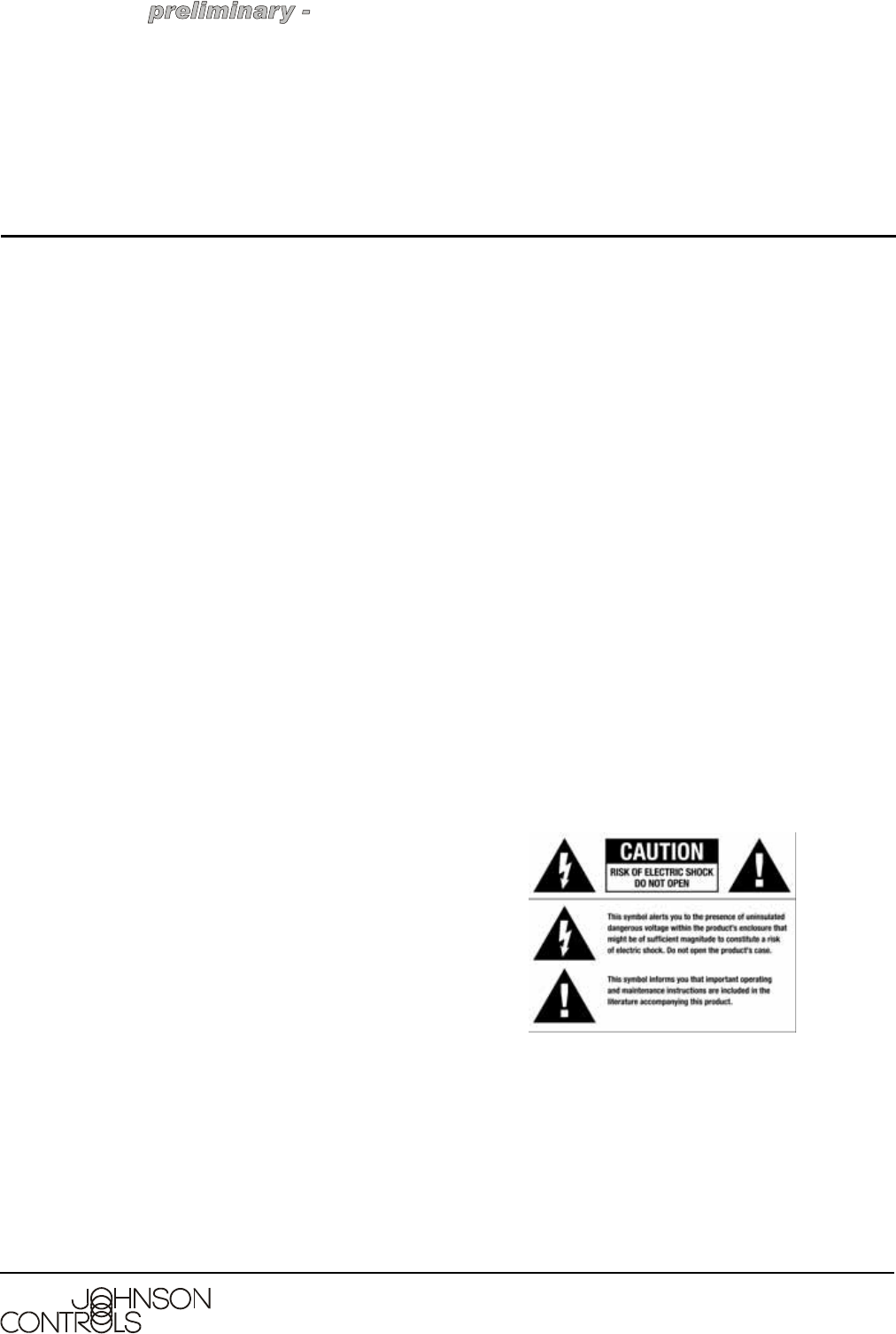
Graphical Symbols on the Device
The following information has been placed on the
device:
System Controller LC-AVMHTC1-0 (HTC)
Installation Guide
LC-AVMHTC1-0 Part No. 21-0250-JC, Rev. A
Release Draft 1
Issued November 13, 2006
Supersedes NA

System Controller LC-AVMHTC1-0 (HTC) Installation Guide2
this information may chang
e
Graphical Symbols in this Guide
The following symbols and their descriptions
draw your attention to important safe practices
and additional information that can help you
avoid injury, death, or loss of material or time.
Emissions Compliance
This product complies with standards established by
the following regulatory bodies:
• Federal Communications Commission (FCC)
• Industry Canada
• Underwriters Laboratories Inc. (UL)
• CE Declaration of Conformity
• Environmental Protection Agency or Other
Designated Local Recycling Agencies
Federal Communications Commission (FCC)
FCC ID: R33AVMHTC11
This device complies with Part 15 of the FCC Rules.
Operation is subject to the following two conditions: (1)
This device may not cause harmful interference, and
(2) this device must accept any interference received,
including interference that may cause undesired
operation.
This equipment has been tested and found to comply
with the limits for a Class B digital device, pursuant to
Part 15 of the FCC Rules. These limits are designed to
provide reasonable protection against harmful
interference in a residential installation. This equipment
generates, uses, and can radiate radio frequency
energy and, if not installed and used in accordance
with the instructions, may cause harmful interference to
radio communications.
However, there is no guarantee that interference will
not occur in a particular installation. If this equipment
does cause harmful interference to radio or television
reception, which can be determined by turning the
equipment off and on, the user is encouraged to try to
correct the interference by one of the following
measures:
• Reorient or relocate the receiving antenna.
• Increase the separation between the equipment
and receiver.
• Connect the equipment into an outlet on a circuit
different from that to which the receiver is
connected.
• Consult the dealer or an experienced radio/TV
technician for help.
Industry Canada
This Class B digital apparatus complies with Canada
ICES-003.
Cet appareil numérique de la classe B est conforme à
la norme NMB-003 du Canada.
Underwriters Laboratories Inc. (UL)
This product has been
tested by UL and has
been found to be in
compliance with:
UL 60065:2003: Standard
for Audio, Video and
Similar Electronic Apparatus — Safety Requirements
CAN/CSA-C22.2 No. 60065-03, First Edition
!
WARNING: Risk of a potentially hazardous
situation that, if not avoided, may result in
death or serious injury. DO NOT IGNORE A
WARNING!
!
CAUTION: Risk of a potentially hazardous
situation that, if not avoided, may result in
minor or moderate injury. DO NOT IGNORE
A CAUTION!
IMPORTANT: Any changes or modifications not
expressly approved by the party responsible for
compliance could void the user’s authority to
operate this equipment.
System Controller LC-AVMHTC1-0 (HTC) Installation Guide 3
this information may chang
e
Important Safety Instructions
1. Read these instructions.
2. Keep these instructions.
3. Heed all warnings.
4. Follow all instructions.
5. Do not use this apparatus near water.
6. Clean only with dry cloth.
7. Do not block any ventilation openings. Install in
accordance with the manufacturer’s instructions.
8. Do not install near any heat sources such as
radiators, heat registers, stoves, or other apparatus
(including amplifiers) that produce heat.
9. Do not defeat the safety purpose of the polarized
or grounding-type plug. A polarized plug has two
blades with one wider than the other. A grounding
type plug has two blades and a third grounding
prong. The wide blade or the third prong are
provided for your safety. If the provided plug does
not fit into your outlet, consult an electrician for
replacement of the obsolete outlet.
10. Protect the power cord from being walked on or
pinched particularly at plugs, convenience
receptacles, and the point where they exit from the
apparatus.
11. Only use attachments/accessories specified by the
manufacturer.
12. Refer all servicing to qualified service personnel.
Servicing is required when the apparatus has been
damaged in any way, such as power-supply cord or
plug is damaged, liquid has been spilled or objects
have fallen into the apparatus, the apparatus has
been exposed to rain or moisture, does not operate
normally, or has been dropped.
13. This apparatus has no AC mains power switch.
The appliance coupler is the AC mains disconnect
device. As such, the appliance coupler must
remain readily operable; that is, it must be readily
accessible, and operation of the disconnect device
must be free from obstruction.
This CLASS I apparatus must be connected to an AC mains
socket outlet that has a protective earthing connection (i.e.,
third-prong ground conductor). DO NOT DEFEAT THE
PROTECTIVE EARTHING CONNECTION!
CE Declaration of Conformity
Environmental Protection Agency or Other
Designated Local Recycling Agencies
For information on recycling, please go to
www.<website placeholder>.com/recycling
!
WARNING: Risk of fire or electrical shock,
do not expose this apparatus to rain or
moisture.
DeClaration OF CONFORMITY
Johnson Controls, Inc., 5757 N. Green Bay Avenue, P.O. Box 591,
Milwaukee, WI 53201, Tel (414) 524-1200
Product: System Controller (HTC), Model No: LC-AVMHTC1-0
The undersigned hereby declares, on behalf of Johnson Controls,
Inc., that the above-referenced product, to which this
declaration relates, is in conformity with the provisions of:
Council Directive 89/336/EEC (May 3, 1989) on Electromagnetic Compatibility
Council Directive 1999/5/EC (Mar 9, 1999) on Radio & Telecommunication
Terminal Equipment (R&TTE)
Council Directive 73/23/EEC (Feb. 19, 1973) on Low Voltage Equipment Safety
Council Directive 93/68/EEC (Jul. 22, 1993) Amending Directives 89/336/EEC and
73/23/EEC
and has been tested to the requirements of, and shown to be in
compliance with, the following requisite standards:
EMC
EN 301 489-1 V1.4.1 — Electromagnetic compatibility and Radio
spectrum Matters (ERM); ElectroMagnetic Compatibility (EMC)
standard for radio equipment and services–Part 1 Common technical
requirements.
EN 301 489-17 V1.2.1 — Electromagnetic compatibility and Radio
spectrum Matters (ERM); ElectroMagnetic Compatibility (EMC)
standard for radio equipment and services; Part 17: Specific
conditions for 2.4 GHz wideband transmission systems and 5 GHz
high performance RLAN equipment.
AS/NZS CISPR 22: 2002 — Information Technology Equipment –
Radio disturbance characteristics.
Radio
EN 300 328-2 V1.4.1 — Wide band transmission systems; data
transmission equipment operating in the 2.4GHz ISM band.
Harmonised EN covering essential requirements under Article 3(2)
of the R&TTE Directive.
AS/NZS 4771: 2000 — Spread Spectrum Equipment using 900MHz,
2.4GHz and 5.8GHz bands.
Safety
IEC 60950-1: 2001 (1st Edition) and/or EN 60950-1: 2001 —
Information Technology Equipment—Safety with national and group
differences in accordance with CB Bulletin No. 109A December 2005:
AS/NZS 60950-1: 2003.
The Technical Construction File required by these Directives is
maintained at the corporate headquarters of Johnson Controls,
Inc., Milwaukee, WI U.S.A.
Signed,
Paul E. Nagel—Vice President of Engineering, May 23, 2006
System Controller LC-AVMHTC1-0 (HTC) Installation Guide4
this information may chang
e
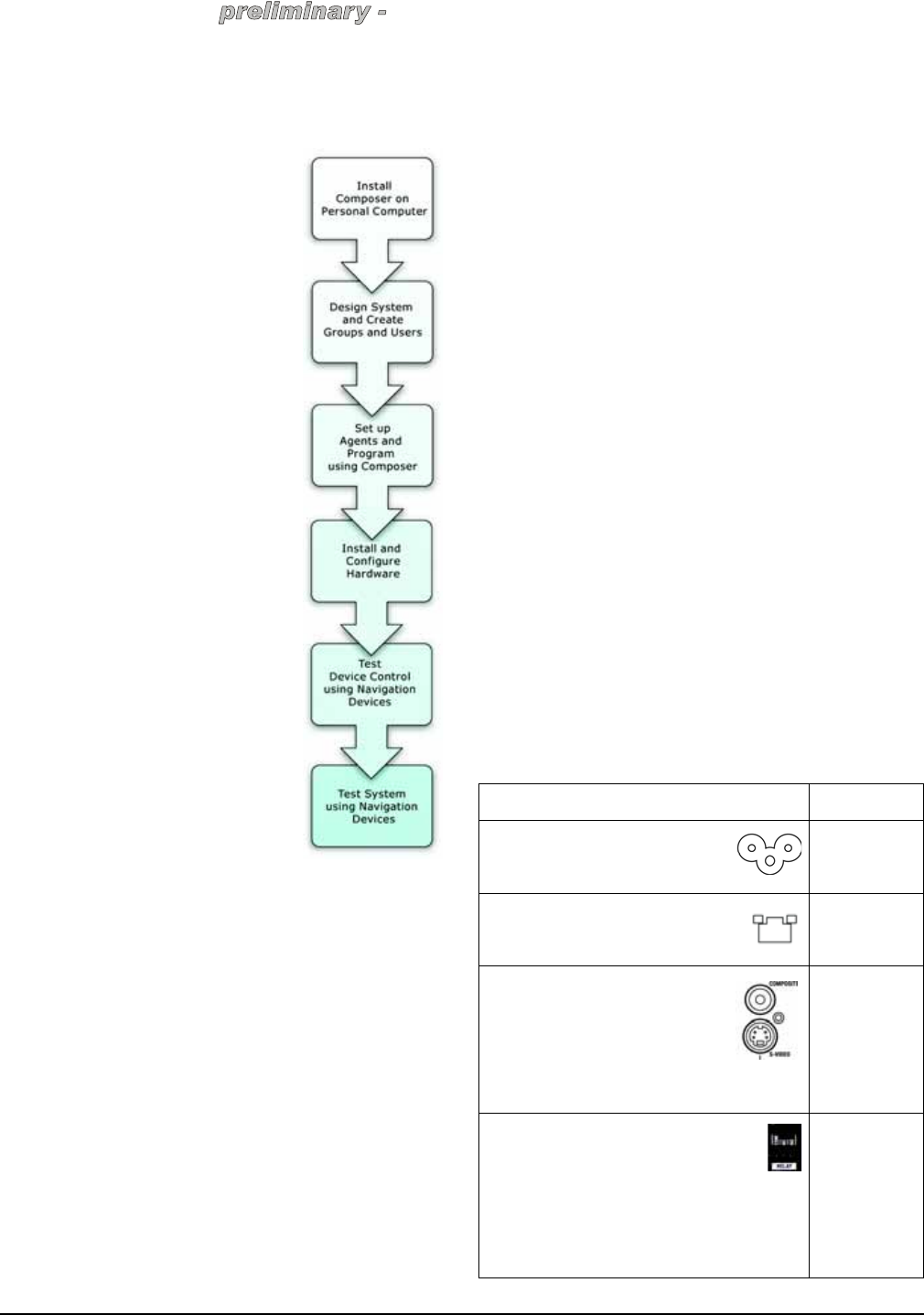
Installation
The installation of a fully functional Touch4 system
includes the following steps:
1. Install Composer software on
Personal Computer.
2. Design System and Create
Groups and Users.
3. Set up Agents and Program
using Composer.
4. Install and Configure Hardware.
5. Test Device Control using
Navigation Devices.
6. Test System using Navigation
Devices.
This document outlines how to install
hardware in this process. For more
information about how to do the other
stages, see the Composer online
help.
Parts Included
The following are included in your
product:
• System Controller (HTC) LC-
AVMHTC1-0
• Pluggable terminal block
connector (1)
• IEC power cord
Installing Composer Software
on Personal Computer
When setting up a Touch4 system,
you need to design your system using the Composer
software. The Composer software is installed on your
Personal Computer and communicates to the System
Controller via the TCP/IP-based network. The
Composer software communicates to the System
Controller using the network.
To install Composer software:
1. Ensure that the software and hardware
requirements are met. See “Applications or
Application Requirements” on page 1.
2. Ensure that your PC is connected to the Internet.
3. Launch the Composer installation and follow the
instructions on the Z10 Touch Screen.
4. Follow the instructions on the Z10 Touch Screen to
update to the latest version of Composer.
5. During the installation process, click the Continue
Anyway button for the installation to proceed.
Designing System and Creating Groups and
Users
Designing the system includes using the Composer
software to determine the make up of the Touch4
system. Within the Composer software, you define the
project tree to build the system design. It includes
defining the building, tenants, floors, and areas, and
the devices that you want to control on the system.
You also need to create groups and users at each area
location and define their respective rights to a given
area. Tenants are given the administration rights to
make changes in that domain as defined by building
administrators.
An important part of designing the system is backing up
the design in a project file that you can load later to the
System Controller. See Composer Online help for
information about how to design a Touch4 System.
Installing and Configuring Hardware
In order to use the Touch4™ system to control devices,
you must install the hardware and make physical
connections between devices, then mirror the physical
connections with logical connections in the software
project. Use Table 1, “Connection Worksheet for
System Controller” to plan and make physical
connections and then make the logical connections
within the Composer software.
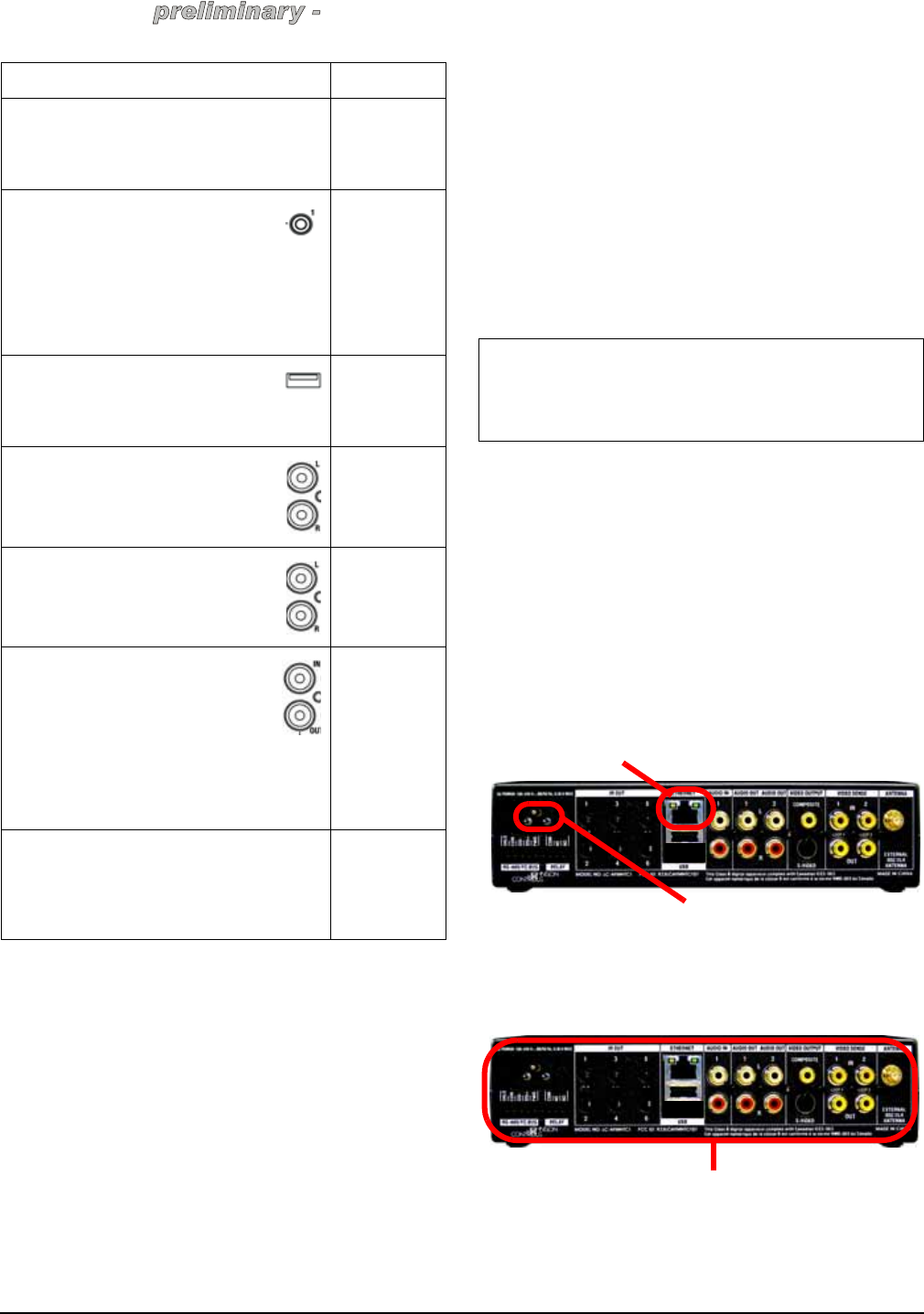
Table 1: Connection Worksheet for System
Controller
Connection Options and Typical Use Reserved for:
Power plug port—For C6 power
connector. See “Installing Hardware”
for more information.
1. For C6
power
connector.
Ethernet—RJ-45 for a 10/100 BaseT
Ethernet connection. See “Installing
Hardware” for more information.
1.
Video Out Options—Composite or
S-Video port for displaying
navigation menus on a monitor or
TV. When available, use S-Video
instead of Composite for a higher
quality display. See “Installing
Hardware” for more information.
1.
Relay (1 set)—Pluggable terminal block
connector for 1 normally closed or
normally opened switchable connection,
such as a blind, a fireplace, or a projector
screen. The set contains a connection for
Common (COM) and Normally Closed (NC) or
Normally Opened (NO). See “Connecting to the
Relay Port” for more information.
1.
System Controller LC-AVMHTC1-0 (HTC) Installation Guide 5
this information may chang
e
To install and configure hardware:
1. Install hardware and make physical connections.
2. Connect to a System Controller’s Director.
3. Load project.
4. Make and verify logical connections.
5. Configure devices.
6. Update devices (firmware - software that resides
on the devices).
7. Set up music and playlists.
Installing Hardware
This section includes setting up the System Controller
hardware and installing other devices on the control
system, such as dimmers, switches, navigation
devices, thermostats, etc. It also includes installing the
physical cables, such as Ethernet cables, contact,
relays, etc. It includes connecting the PC and the
System Controller using Ethernet cables to the local
area network as they communicate with each other
through the local area network. This documentation
assumes that the local area network that is either using
Ethernet or WiFi is already set up.
To install the System Controller and other System
Devices:
1. Connect PC to live TCP/IP Ethernet network (Local
Area Network or LAN). Use either a wireless
access point or Ethernet cable to connect the PC
to the office network.
2. Connect System Controller to Ethernet Local Area
Network (LAN) using the RJ-45 labeled Ethernet
on the back of the System Controller. If successful,
the amber LED turns on and the green LED blinks.
3. Power up System Controller using the power cord
provided.
4. Install all other system devices, hardware, cables,
and networks that you intend to control on the
Touch4 system as instructed in the accompanying
documentation.
BACnet/FLBus (1 set)—Pluggable terminal
block connector for 1 BACnet/FLBus, such as a
thermostat. See “Using BACnet/FLBus Port” for
more information.
1.
IR Out (6)—3.5 mm jacks for up to 6 IR
output transmitters. See “Setting Up IR
Emitters” for more information.
1.
2.
3.
4.
5.
6.
USB (1 port)—For external storage
device with USB support (such as FAT32
formatted devices). See “Set up External
Storage Device” for more information.
1.
Audio In (1 Left-Right pair)—RCA jacks
for stereo channel input (line level) for 1
stereo analog source.
1.
Audio Out (2 Left-Right pairs)—RCA
jacks for stereo channel line output (line
level) for amplifiers or audio switches.
2.
3.
Video Sense In-Out (2 pairs)—
Composite In-Out port pairs for
monitoring up to 2 video In sources,
such as DVD players or VCRs, that allow
the system to determine the On/Off
status of devices. Each Out port allows the signal
to loop through the System Controller and
continue to its intended video connection. See
“Using Video Sense Loops” for more information.
1.
2.
External 802.15.7 Antenna—Whip antenna for
providing external radio signal when the System
Controller is stored in a signal-inhibiting area
(such as a steel utility closet). See “Using
External 802.15.7 Antenna” for more information.
3.
4.
Connection Options and Typical Use Reserved for:
IMPORTANT: You must use the Local Area
Network for communication between the PC and the
System Controller. You cannot connect the PC and
System Controller directly using the Ethernet port.
Ethernet
Power
BACnet, IR Out, Audio IN, Audio Out, Video
Output, Video Sense Ports, and Antenna
System Controller LC-AVMHTC1-0 (HTC) Installation Guide6
this information may chang
e
Note: USB Port: To make music saved to a USB drive
available to the system, use the USB port on the back
of the System Controller. The USB port is only for
music storage use and USB updates. You cannot use
it to connect the PC directly to the System Controller.
Connections
Connect all applicable devices to the System Controller
using one of the available connection methods
including those described on Table 1, “Connection
Worksheet for System Controller”. Connect all
applicable devices to the System Controller. The
following sections provide guidelines on making the
various connections, including:
• Using Pluggable Terminal Block Connectors
• Using BACnet port
• Connecting to the Relay Port
• Setting Up IR Emitters
• Using USB Port to Set up External Storage Device
• Using Video Sense Loops
Using Pluggable Terminal Block Connectors
For the Contact, Relay, and BACNET ports, the System
Controller makes use of a pluggable terminal block
connector—a removable plastic part to lock in
individual wires. This connector is included.
To connect a device to the Pluggable Terminal Block:
1. Insert one of the wires required for your device into
the appropriate opening in the Pluggable Terminal
Block you reserved for that device (refer to Table 1
on page 4).
2. Lower the openings latch until it locks the wire in
place.
3. Repeat Steps 1-2 for all wires required for your
device.
Using BACnet/FLBus ports
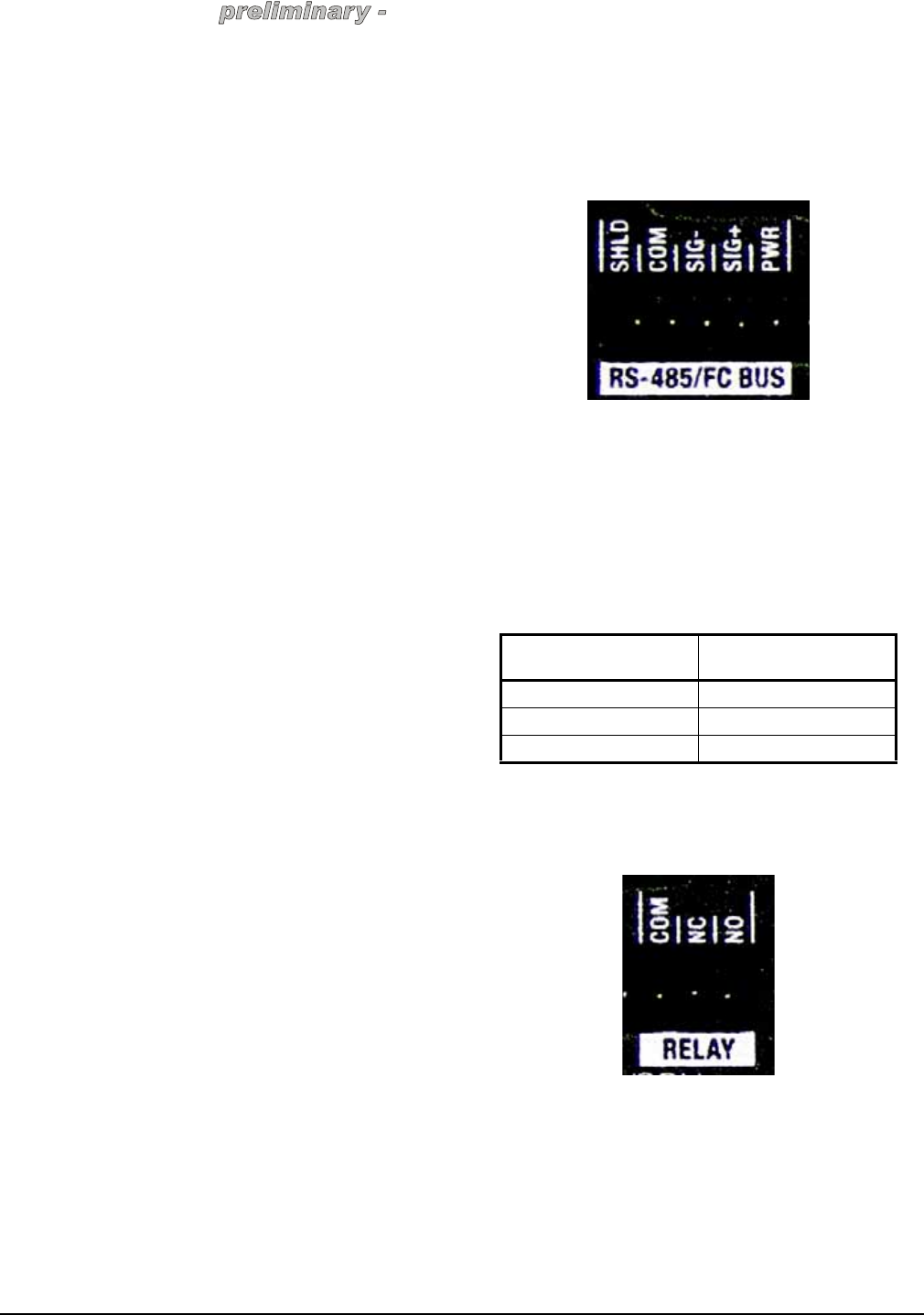
The System Controller provides one BACnet® Network
port (labeled RS-485/FC-Bus as a subset of the
pluggable terminal block provided). See the following
figure to determine how to connect to this port.
Figure 1: BACnet (RS-485/FC Bus) Port
For example, to install a BACnet Networked
Thermostat:
1. Install the BACnet® Networked Thermostat and
wire the thermostat’s MS/TP Communications Bus
according to documentation provided and the MS/
TP Communications Bus Technical Bulletin (LT-
12011034).
2. Connect the communication wires from the
thermostat to the System Controller as follows.
Connecting to the Relay Port
The System Controller provides one relay port as a
subset of the pluggable terminal block provided.
Figure 2: Relay Port
Attach one wire to the common terminal and the other
to either the normally open terminal or the normally
closed terminal.
The relay switch closes when the relay is activated.
The System Controller can support applications that
require either a normally closed contact or a normally
open contact.
Wires from Thermostat Terminal Block on
System Controller
COM COM
-SIG -
+SIG +
System Controller LC-AVMHTC1-0 (HTC) Installation Guide 7
this information may chang
e
Setting Up IR Emitters
Your system might contain products that are controlled
with IR commands (usually through remote controls).
Note: IR emitters sold separately in the “Media
Package.”
To provide a way for the System Controller to control a
device that only recognizes IR commands, complete
the following setup:
1. Plug the 3.5 mm connector end of one of the 6 IR
stick-on emitters into an IR Out port on the System
Controller.
2. Place the stick-on emitter end over the IR receiver
on the media player, TV, or other target device to
transmit IR signals from the System Controller to
the target.
Using USB Port to Set up External Storage
Device
When using the System Controller as the primary
System Controller in the office, from the USB port (on
the back), you can store and access media from an
external storage device, such as a network hard drive
or USB memory device.
3. For more information, see the Composer online help
topic: “Use External Storage Devices.”
Using Video Sense Loops
Video sensing can enhance the ability to sense the
power state of a device, such as whether the device is
“on” or “off.” If you need to add video signal sensing
capabilities for a video device (such as a TV, VCR,
DVD player, etc.), connect one of the device’s
composite Video Out ports to a System Controller
Video Sense In port. Then, use the companion Video
Sense Out port (where available) for the device’s video
out as needed.
For Video Sense only (no loop-through), connect a
device’s Composite Video Out port to one of the two
Video Sense In ports.
Using External 802.15.7 Antenna
Setup and Adjustments
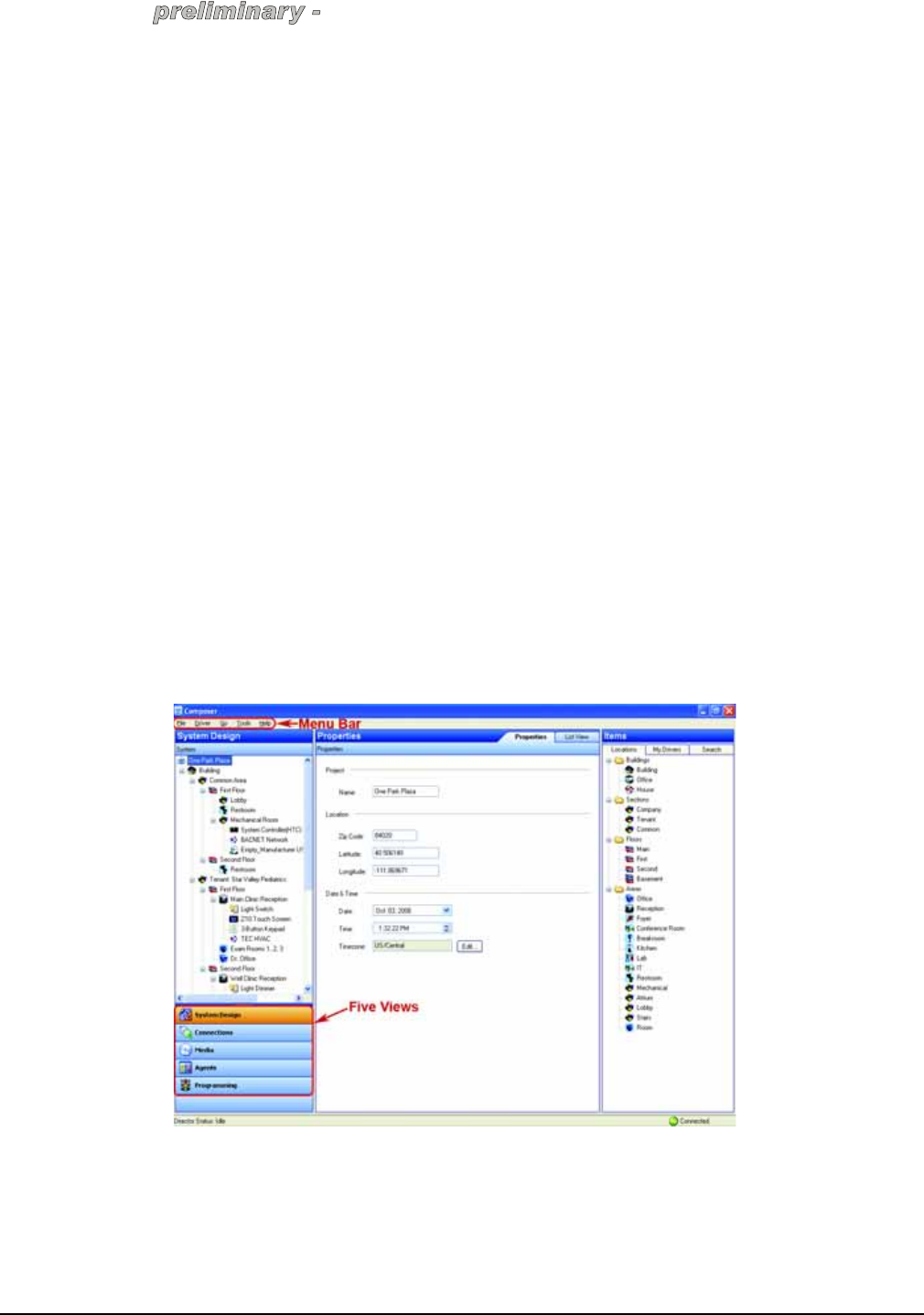
Figure 3: Windows XP-based Composer
Johnson Controls Composer is a Windows XP-based
PC program that has an intuitive drag-and-drop
interface. This interface enables you to fully design, set
up, and program the Touch4 system that automates
and schedules HVAC, lighting, security and other
devices found within a light commercial environment.
To take advantage of its features, Composer has five
main views:
•System Design — Allows you to build the Project
Tree and identify the devices on the system. See
Composer online help for more information.
System Controller LC-AVMHTC1-0 (HTC) Installation Guide8
this information may chang
e
•Connections — Allows you to identify all
connections (Room, Control, AV, Network). See
Composer online help for more information.
•Media — Allows you to add and scan stored or
broadcast media. See Composer online help for
more information.
•Agents — Allows you to set up agents for use on
the system and programming. Agents include:
lighting scenes, wake up, scheduler, variables, etc.
See Composer online help for more information.
•Programming — Allows you to program devices
and agents on the system. See Composer online
help for more information.
Note: Click and pull down the
dotted bar to make the navigation
views collapsible to give you more
room to view the Project Tree.
The Menu Bar provides the following menus:
•File menu — Use to perform typical file
management tasks, connect or disconnect to the
local director, update the Composer software and
exit Composer. See the Touch4 System User
Guide for more information.
•Media menu (appears when Media view is
selected) — Use to perform tasks regarding music
and media lists. See the Touch4 System User
Guide for more information.
•Go Menu — Use to access the various Composer
views, including System Design (Ctrl+1),
Connections (Ctrl+2), Media (Ctrl+3), Agents
(Ctrl+4), and Programming (Ctrl+5). Short cuts are
also available to this views as indicated. See the
Touch4 System User Guide for more information.
•Tools menu — Use to view network status and
logs. See the Touch4 System User Guide for more
information.
•Help menu — Use to view on-line help and version
information. See the Touch4 System User Guide
for more information.
Operation
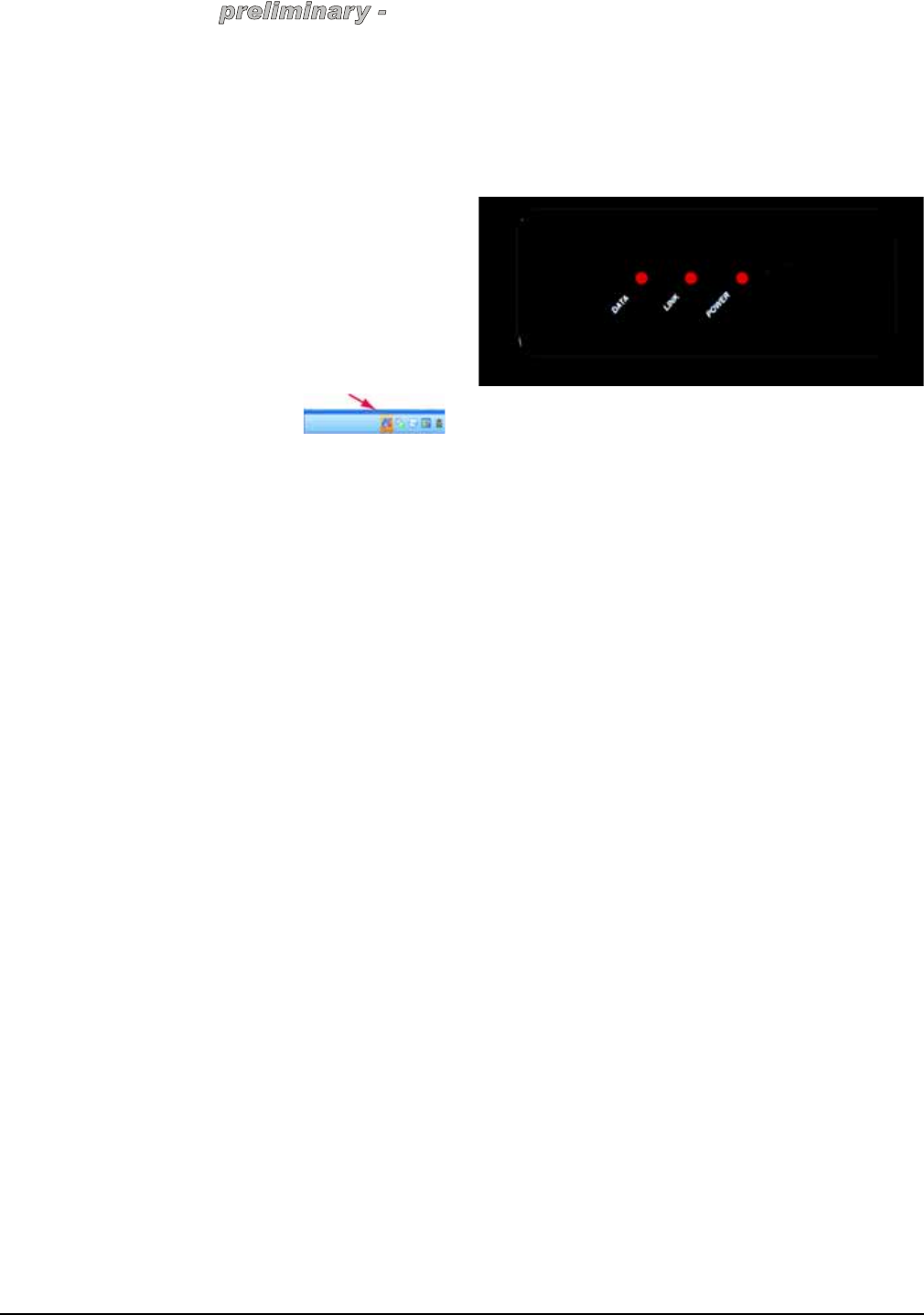
Using the Front Panel
The operation of the System Controller is mostly from
the Navigation devices on the Touch4 system.
1. IR window — For capturing third-party IR codes
from hand-held devices (such as remote controls).
2. Data LED — Red LED light indicates data is
received.
3. Link LED — Red LED light indicates System
Controller has been identified in a project
configuration.
4. Power LED — Red LED light indicates AC power
is present. This LED will turn on approximately 30
seconds after the power is applied to the device.
5. Identification/Reset Button — For identifying this
device to the system during initial setup. This
button also serves as the device reset button when
pressed for 10 seconds or more.
For systems operations, see the Touch4 System User
Guide.
Repairs and Replacement
For repairs or replacement, contact Technical Support.
About this Document
Control4 and the Control4 logo are registered
trademarks of Control4 Corporation. All Johnson
Controls, Inc. and third-party trademarks are properties
of their respective owners. Part Number: 21-0250-JC
Rev A

System Controller LC-AVMHTC1-0 (HTC) Installation Guide 9
this information may chang
e