Snap One LDZ1011 LDZ-101-X Controllable Dimmer User Manual WirelessDimmer
Control4 LDZ-101-X Controllable Dimmer WirelessDimmer
Snap One >
Exhibit 8
Control4 Wireless Dimmer Installation and User Guide 1
Wireless Dimmer
Installation and
User Guide
Supported Models and Fixtures
This installation and user guide covers these dimmer models:
This dimmer can operate independently or as a device you can
control with your Control4 system. The dimmer installs in a standard
wall box using typical wiring standards and it communicates to the
Control4 system using a wireless connection.
The dimmer supports:
•120 Volt incandescent (all types)
•120 Volt halogen (all types)
•120 Volt magnetic low voltage
(all types with 70 percent or greater load factor)
•120 Volt electronic low voltage (dimmable only)
•120 Volt fluorescent light fixtures (dimmable only)
Installation Instructions
Ensure that the location and intended use meet the
following criteria:
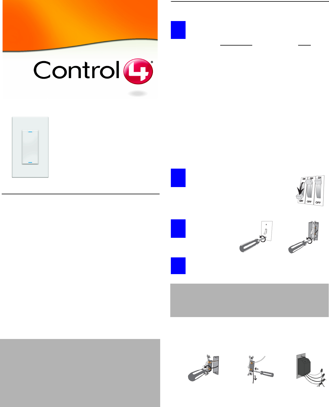
To avoid injury or death, turn OFF local
electrical power. To turn off the power,
either switch off the circuit breaker or
remove the fuse from fuse box. To ensure
the wires do NOT have power running to
them, use an inductive voltage detector.
Use screwdriver
to remove wall
plate and
existing switch
from wall.
Detach existing dimmer or switch.
The existing dimmer or switch is wired in one of three ways:
terminal screws, backwire, or wire nuts.
LDZ-101-W Wireless Dimmer (802.15.4)
LDZ-101-B Wireless Dimmer (802.15.4)
LDZ-101-A Wireless Dimmer (802.15.4)
WARNING! To reduce the risk of serious injury or death, turn all
power OFF before installing this product. Using this
product in a manner other than outlined in this
document voids your warranty. Further, Control4 is
NOT liable for any damage incurred with the misuse of
this product. See “Limited 1 Year Warranty” on page 6.
This product generates heat. The room must have
adequate ventilation or heat dissipation ability. Do
NOT use this device to control a device with a non-
dimmable load. You should only use it with devices
that have dimmable feature support.
DO (OK, Normal) DON’T
•Install in accordance with all
national and local electrical
codes.
•Wall box size required depends
on your wiring. The dimmer alone
needs a depth of 2.5 inches. To
calculate the total depth required,
add 2.5 inches to the amount of
space recommended in the NEC
(National Electric Code) for your
configuration.
•The range and performance of
the control system is highly
dependent on the following:
• Distance between devices
• Layout of the home
• Walls separating devices
• Electrical equipment
located near devices
•If installing a
multi-unit dim-
mer, Do NOT
continue until
you have read
“Multi-Unit
Installations” on
page 2.
•Do NOT use
where total watt-
age is under 25
watts.
•Do NOT exceed
maximum load
rating of dimmer
(which is 1000W
for a single unit,
if both side tabs
are in tact).
WARNING! As with any appliances, improper use or installation
can cause SERIOUS INJURY or DEATH. Do NOT
attempt the installation if you are NOT sure which
wires are the hot and load wires in the wall box.
Instead, have a trained electrician do the installation.
Terminal Screws:
Use a screwdriver to
unscrew the screws
to release the wire.
Backwire:
Insert screwdriver in
Wire Release slot and
pull out wire. If this does
not work, use a wire
cutter to cut the wire.
Wire Nuts:
Turn to remove
wire nuts from
existing wiring.
1
2
3
4
OR OR
Control4 Wireless Dimmer Installation and User Guide 2
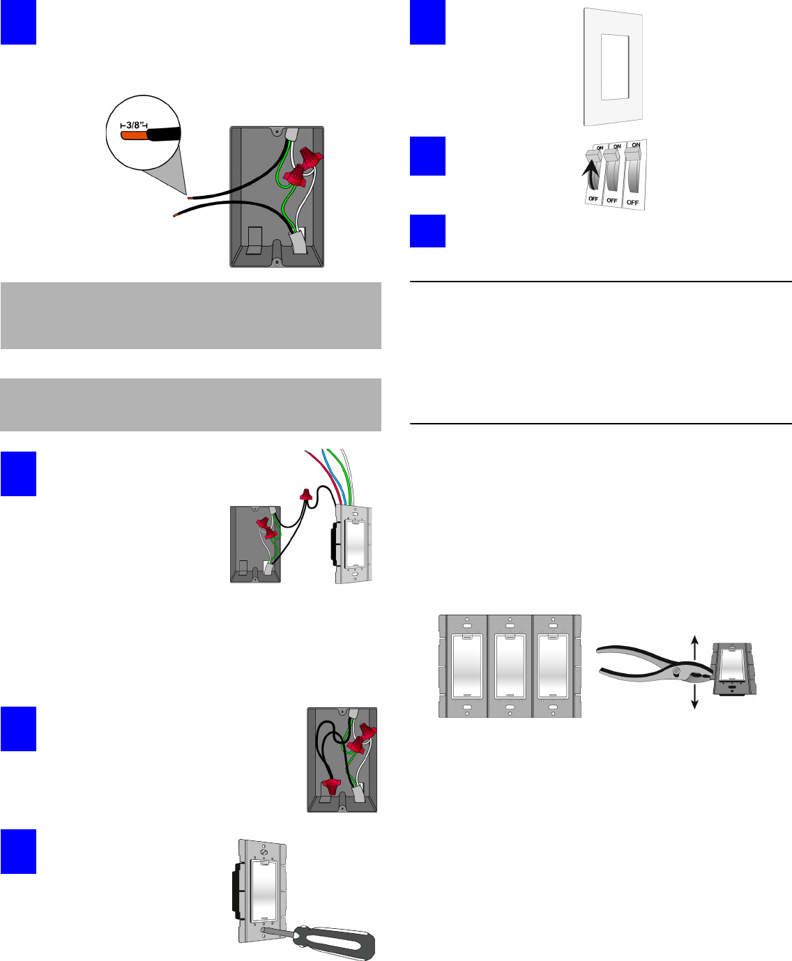
Prepare and identify all wires. Identify the wires in your
wall box. Straighten the wire ends. With a wire cutter, cut off
the bare wire just below the plastic insulation on all wires.
Use a wire stripper to strip off about 3/8-inch of the
insulation.
Connect the dimmer wires
to the wall box wires using
wire nuts. Wall box wires
can differ depending upon
how the box was wired by
your electrician and where
the power source comes
from—the light fixture or the
wall box. Refer to the
following four sections
(beginning on page 3):
• “Single-Switch Environment—Power Source at Wall Box”
• “Single-Switch Environment—Power Source at Light Fixture”
• “3-Way-Switch Environment—Power Source at Wall Box”
• “3-Way-Switch Environment—Power Source at Light Fixture”
Fit wires back into the wall box. Bend the
wires in a zigzag pattern so that they easily
fold into the wall box. Push the dimmer into
place. Adjust the dimmer so that it is
perpendicular to the floor. Tighten the two
screws that hold it in position in the wall box.
Align dimmer to wall box and
fasten with screws, unless
you are using a Decora screw-
on-style wall plate. If you are
using a screw-on-style wall
plate, before fastening with
screws, you must first align the
wall plate with the dimmer and
the wall box.
If you are using
the Control4
snap-on- style
wall plate, snap it
over the dimmer
now.
Turn ON power at
the circuit breaker
or replace fuse
from fuse box.
Test the dimmer to see if it is working properly. For
details, see “Operation and Configuration” on page 5.
Troubleshooting
If light does not turn on:
•Ensure light bulb is not burned out.
•Ensure light bulb is screwed in tightly.
•Ensure circuit breaker is not turned OFF or tripped.
•Check for proper wiring (see the subsections beginning on page 3).
Multi-Unit Installations
Multi-unit installations allow you to install one stand-alone dimmer
next to another in the same wall box.
Remove Inner Sides
When using multiple units in a wall box, you must remove the inner
sides, leaving the outer sides in place. Use pliers to bend a tab
back and forth until it comes off. Remove only the sides that will touch
another dimmer. Do not remove sides that will become outer sides.
Resulting Capacity
•With both sides intact (single unit), the capacity is 1000W maximum.
•If you remove one side, the capacity is reduced to 800W maximum.
•If you remove two sides, the capacity is reduced to 600W maximum.
IMPORTANT: The National Electric Code (NEC) requires 6 inches of
extended wire from the wall box. If your wiring does
not meet this requirement, you will not meet code. Do
NOT cut wire shorter than 6 inches.
IMPORTANT: When installing this product in a commercial
application or metal wall box, you might need to
ground it to the wall box.
5
6
7
8
9
10
11
Control4 Wireless Dimmer Installation and User Guide 3
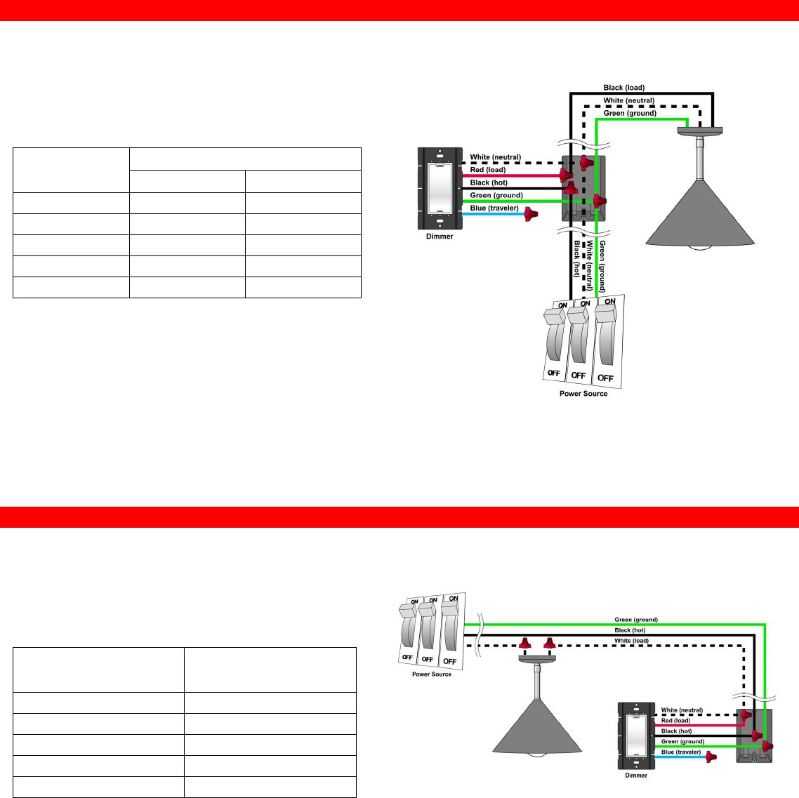
Single-Switch Environment—Power Source at Wall Box
To wire the dimmer for a Control4 single-switch environment when
the power is coming from the wallbox, connect together and cap
with a wire nut the wires indicated in the following table:
Single-Switch Environment—Power Source at Light Fixture
To wire the dimmer for a Control4 single-switch environment when
the power is coming from the light fixture (switched-leg mode),
connect together and cap with a wire nut the wires indicated in the
following table:
Wires from dimmer Wires from Wall Box
Light Fixture Power Source
White (neutral) White (neutral) White (neutral)
Red (load) black (load) None
Black (hot) None Black (hot)
Green (ground) Green (ground) Green (ground)
Blue (3-way traveller) None None
Wires from dimmer Wires from the Wall Box
(coming from the power
source at light)
White (neutral) White (load)
Red (load) White (load)
Black (hot) Black (hot)
Green (ground) Green (ground)
Blue (3-way traveller) None
Control4 Wireless Dimmer Installation and User Guide 4
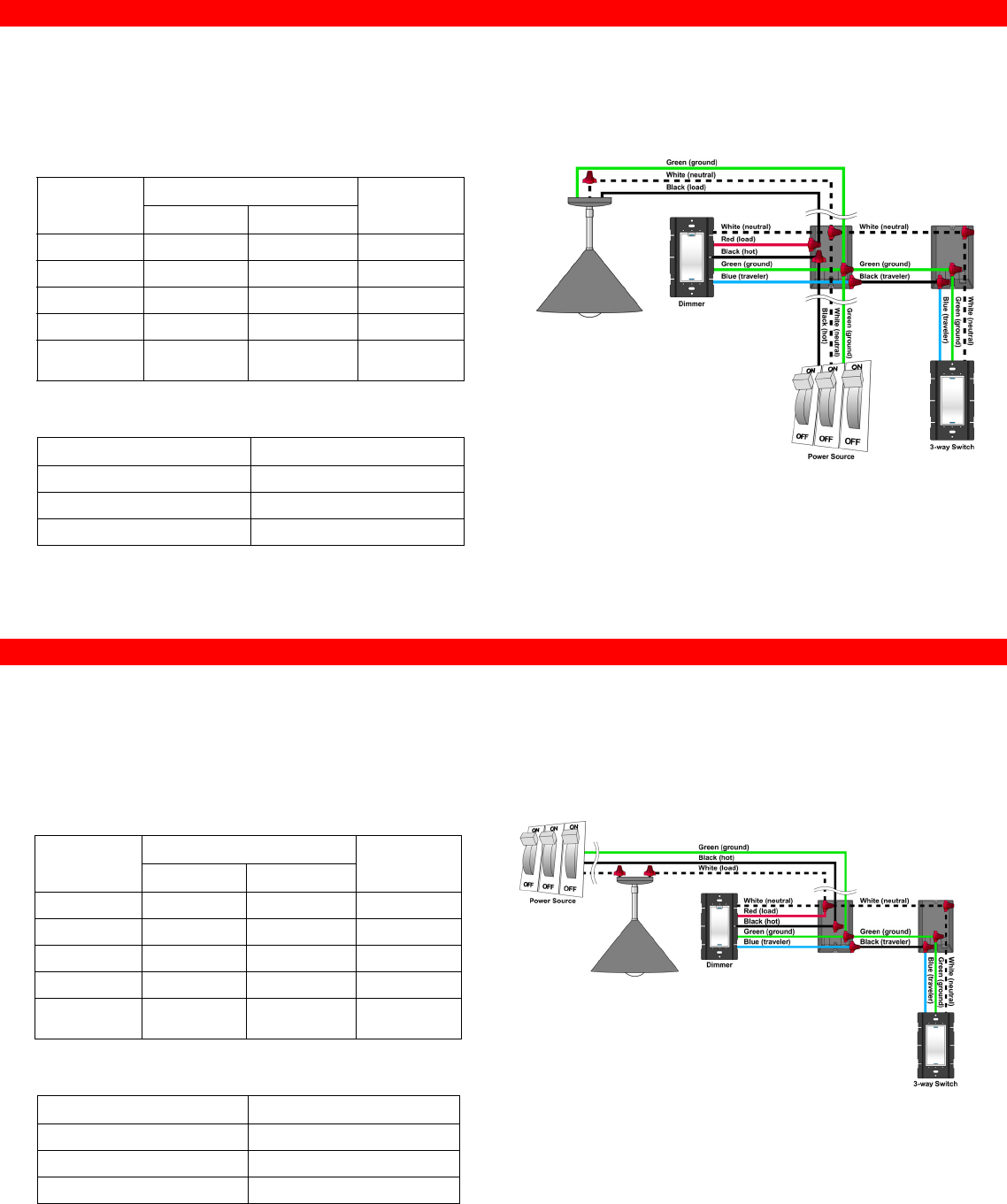
3-Way-Switch Environment—Power Source at Wall Box
To wire the dimmer for a Control4 3-way-switch environment when the
power is coming from the wall box, do the following:
1. Wire the dimmer to Wall Box 1 by connecting together and capping with a
wire nut the following wires:
2. Wire the 3-way keypad to Wall Box 2 by connecting together and capping
with a wire nut the following wires:
3-Way-Switch Environment—Power Source at Light Fixture
To wire the dimmer for a Control4 3-way-switch environment when the
power is coming from the light fixture (switched-leg mode), do the
following:
1. Wire the dimmer to Wall Box 1 by connecting together and capping with a
wire nut the following wires:
2. Wire the 3-way keypad to Wall Box 2 by connecting together and capping
with a wire nut the following wires:
Wires from
dimmer
Wires from Wall Box 1 Wires from
Wall Box 2
Light Fixture Power Source
White (neutral) White (neutral) White (neutral) White (neutral)
Red (load) black (load) None None
Black (hot) None Black (hot)
Green (ground) Green (ground) Green (ground) Green (ground)
Blue (3-way
traveller)
None None Black (3-way
traveller)
Wires from 3-way Keypad Wires from Wall Box 2
White (neutral) White (neutral)
Green (ground) Green (ground)
Blue (3-way traveller) Black (3-way traveller)
Wires from
dimmer
Wires from Wall Box 1 Wires from
Wall Box 2
Light Fixture Power Source
White (neutral) White (load) None White (neutral)
Red (load) White (load) None None
Black (hot) None Black (hot) None
Green (ground) None Green (ground) Green (ground)
Blue (3-way
traveller)
None None Black (3-way
traveller)
Wires from 3-way Keypad Wires from Wall Box 2
White (neutral) White (neutral)
Green (ground) Green (ground)
Blue (3-way traveller) Black (3-way traveller)
Control4 Wireless Dimmer Installation and User Guide 5
Operation and Configuration
To configure this dimmer for use with a Control4 system, refer to the
documentation that shipped with your controller.
To operate and configure this dimmer as a stand-alone device, refer to
the following tables.
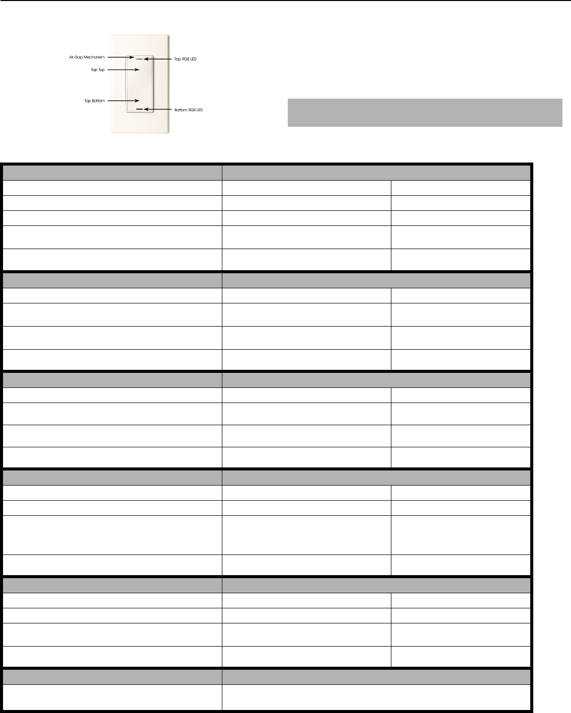
NOTE: RGB LEDs are small lights that can be programmed
with different colors to reflect different states.
Operate Dimmer Expected behavior of RGB LEDs:
To operate dimmer: Top Bottom
Turn ON: Tap top for ON. Lit, full brightness Not lit
Turn OFF: Tap bottom for OFF. Not lit Lit, full brightness
Set dimming level: Press and hold top for higher level or press and
hold bottom for lower level.
Lit, brightness indicates current level of dimming If lit, then a dimming level has been set and
brightness indicates level of dimming
Cut power to light fixture: Pull up on the air gap mechanism for
maintenance to the light bulb or light fixture.
Not lit Not lit
Toggle to Dimmer or Switch Mode Status indicated by RGB LEDs
To toggle between dimmer and switch: Top Bottom
1. Tap bottom 5 times to enter into Dimmer/Switch Mode Select. Green = Dimmer Purple = Dimmer/Switch Mode Select
mode
2. Tap top 1 time to toggle to Dimmer or Switch modes. Green = Dimmer
Blue = Switch
Purple = Dimmer/Switch Mode Select
mode
3. Tap bottom 1 time to save selected mode and exit Dimmer/
Switch Mode Select.
(Returns to default or previous value) (Returns to default or previous value)
Bind 3-Way Status indicated by RGB LEDs
To bind devices for a 3-Way dimmer: Top Bottom
1. Tap bottom 6 times on each device in the 3-Way group to enter
into 3-Way Binding mode.
Red = Ready to receive and build an address table Amber = 3-Way Binding mode
2. Tap top 1 time on each device in the 3-Way group to advertise
its address.
Green = Device address has been advertised Amber = 3-Way Binding mode
3. Tap bottom 1 time to save all advertised addresses and exit 3-
Way Binding mode.
(Returns to default or previous value) (Returns to default or previous value)
Select Channel Status indicated by RGB LEDs
To select a channel: Top Bottom
1. Tap bottom 7 times to enter into Channel Select mode. Red = Channel A Aqua = Channel Select mode
2. Tap top 1 time to toggle to next available channel. Red = Channel A
Blue = Channel B
Green = Channel C
(Other user defined color) = Custom Channel
Aqua = Channel Select mode
3. Tap bottom 1 time to save selected channel and exit Channel
Select mode.
(Returns to default or previous value) (Returns to default or previous value)
Restore Defaults Status indicated by RGB LEDs
To restore default settings: Top Bottom
1. Tap bottom 10 times to enter into Restore Default mode. Red = No action White = Restore Default mode
2. Tap top 1 time to toggle to No Action or Restore Default
modes.
Red = No action
Green = Restore Default
White = Restore Default mode
3. Tap bottom 1 time to execute the selected command and exit
Restore Default mode.
(Returns to default or previous value) (Returns to default or previous value)
Dimmer Surface DOs Dimmer Surface DON’Ts
Dimmer might feel warm to the touch under normal operation.
Clean surface with a soft damp cloth as needed.
Do NOT paint dimmer or wall plate. It is not recommended.
Do NOT use any chemical cleaners to clean the dimmer.

Control4 Wireless Dimmer Installation and User Guide 6
FCC and UL Information
FCC ID = R33LDZ1011
This device complies with Part 15 of the FCC Rules. Operation is
subject to the following two conditions: (1) this device may not cause
harmful interfence, and (2) this device must accept any interference
received, including interference that may cause undesired operation.
UL information: Control number 20MC
Limited 1 Year Warranty
This device has a limited one (1) year warranty on parts from the date
of installation. Control4 will replace or repair any defective unit.
Return unit to the place of purchase for replacement. For any
damages incurred, the warranty will never exceed the purchase price
of the device. This warranty does not cover installation, removal, or
reinstallation cost. The warranty is not valid in cases where damage
incurred due to misuse, abuse, incorrect repair, or improper wiring or
installation. It does not cover incidental or consequential damage.
This warranty gives you specific legal rights, and you might also be
entitled to other rights that vary from state to state. Some states do
not allow limitations on how long an implied warranty lasts or the
exclusion or limitation of incidental or conseqential damages. In these
cases, the above mentioned limitations might not apply to you. To
automatically receive notification of upgrades, register your device by
returning the enclosed registration card or by going to the
MyControl4.com web site.
Control4 Technical Support
For help on the installation or operation of this product, email or call
the Control4 Technical Support Center. Please provide your exact
model number. Contact support@control4.com or see the web site
www.control4.com.
United States Patents Pending.© 2004 Control4 Technologies.
Made and printed in the United States.
Part Number: 21-0000 Rev 1 Draft 12
CAUTION! Changes or modifications not expressly approved by
Control4 could void the user’s authority to operate
the equipment.
CAUTION! To Reduce the Risk of Overheating and Possible
Damage to Other Equipment, Do Not Install To
Control A Receptacle, A Motor-Operated Appliance, A
Flouorescent Lighting Fixture, or A Transformer-
Supplied Appliance.