Snap One LOZ5S11 Wireless Outlet Switch Model LOZ-5S1-X User Manual WirelessOutletSwitch IG
Control4 Wireless Outlet Switch Model LOZ-5S1-X WirelessOutletSwitch IG
Snap One >
Exhibit 8
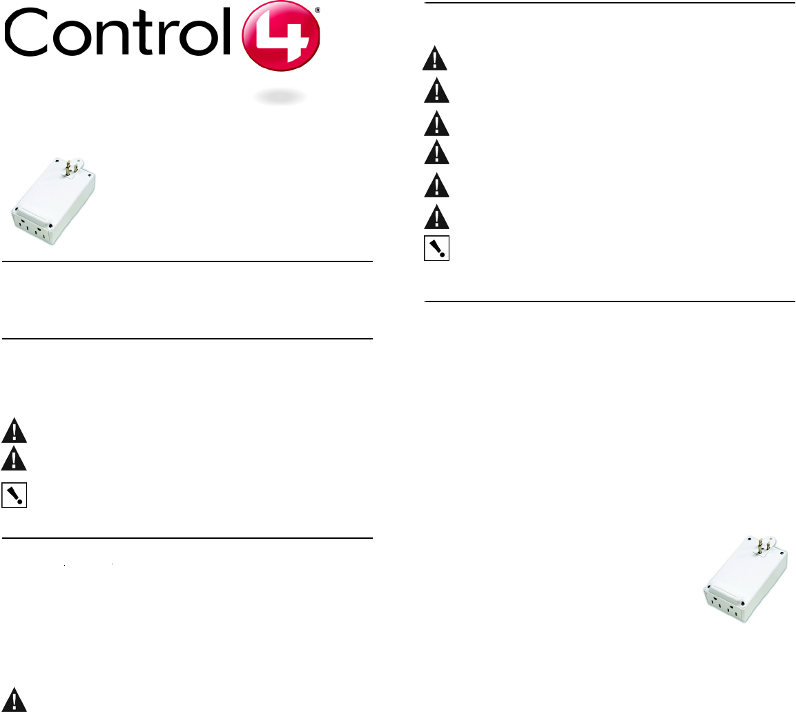
Wireless Outlet
Switch Installation
Guide
Supported Models and Requirements
LOZ-5S1-W Wireless Outlet Switch
Graphical Symbols in this Guide
The following symbols and their descriptions draw your attention to important safe
practices and additional information that can help you avoid injury, death, or loss of
material or time.
WARNING! This indicates a potentially hazardous situation that, if not
avoided, may result in death or serious injury. DO NOT IGNORE A WARNING!
CAUTION! This indicates a potentially hazardous situation that, if not avoided,
may result in minor or moderate injury. DO NOT IGNORE A CAUTION!
IMPORTANT! This indicates information that will help you avoid damage to
your equipment, loss of materials, or loss of time. PAY ATTENTION TO THESE
IMPORTANT STATEMENTS!
Specifications and Supported Fixtures
This Wireless Outlet Switch plugs into a standard, earth-grounded (3-prong)
electrical outlet and communicates with the Control4 system using a wireless
ZigBee connection through its built-in antenna.
Use the Wireless Outlet Switch to control electrical devices such as pumps,
Christmas lights, fans, and fluorescent lights, individually or within a lighting
scene. The Wireless Outlet Switch can sense the power state of the devices
attached to it (On, Off, or Stand-by).
WARNING! The Wireless Outlet Switch is rated for a combined load of 1150
Watts; do not plug in devices that require more than 1150 Watts, either alone or
in combination.
The Control4 Wireless Outlet Switch offers these features:
•Power sensors allow the Control4 system to detect the power state
of the devices you have plugged into each outlet.
•Two tri-color LEDs to indicate outlet activity and system feedback.
•A security screw tab that attaches to the outlet’s center screw.
•An external button for manual operation and to automatically identify
the device to the Control4 system.
Specifications
Important Warnings and Information
WARNING! Improper use or installation can cause SERIOUS
INJURY, DEATH, or LOSS/DAMAGE OF PROPERTY.
WARNING! Install in accordance with all national, state, and local
electrical codes.
WARNING! This product generates heat. The room must have
adequate ventilation or the ability to dissipate heat effectively.
WARNING! This product must be grounded in accordance with the
National Electrical Code (NEC) requirements.
WARNING! Use only in dry locations.
CAUTION! For residential use only.
IMPORTANT! Using this product in a manner other than outlined in this
document voids your warranty. Further, Control4 is not liable for any
damage incurred because of the misuse of this product. See “Limited
1 Year Warranty” on page 2.
Install and Configure a Wireless Outlet Switch
To enable full use of the Control4 system’s features, configure your Wireless
Outlet Switch to read the power state of the devices that you plug into it. For
example, if your switch can read the power state of the DVD player, your
DVD player can then participate in concert with the lights and the other
devices in your home theater in a lighting scene.
1 Choose a location where the ZigBee wireless communication will be
most efficient: (1) Place the Outlet Switch near enough to the next
ZigBee device to facilitate communication (2); Keep the Outlet Switch
from being continually too close to devices that can cause interference,
such as microwave ovens or cordless telephones with a 2.4 GHz
frequency.
2 Remove the screw that holds the faceplate onto
the AC outlet to which you will plug the Wireless
Outlet Switch.
3 Plug the Wireless Outlet Switch into the
receptacle of the outlet, keeping the faceplate
between the Wireless Outlet Switch and the
wall.
4 Through the Wireless Outlet Switch’s security screw tab, insert the
screw that you removed in Step 2 and then screw it back in place.
5 Within Composer software, add the outlet to the project and make
necessary connections. See “Configure an Outlet Switch or Dimmer” in
Composer online help.
To identify the Wireless Outlet Switch as part of the Composer software
configuration, press the button on the top panel of the Wireless Outlet
Switch.
6 Plug in the device you would like to control, such as a DVD player, into
one of the Wireless Outlet Switch’s receptacles (on the bottom panel).
7 Push and hold the button on the top panel of the Wireless Outlet Switch
until the two LED lights flash orange, On and Off, from one to the next.
8 When the LED lights up on the side that corresponds to the outlet in
which your device is plugged, release the button. For example, if the
device you have plugged in is on the right side of the Wireless Outlet
Switch, release the button when the LED lights on the right side.
The LED on that side of the switch alone flashes orange, indicating that
it is in the first phase of learning the state (Off) of the device. When it
has completed this learning phase, the LED then shines solid orange.
9 When the LED shines solid orange, turn On the device that you have
plugged into the Wireless Outlet Switch. The LED light again flashes
orange while the Wireless Outlet Switch completes the first phase of
Power Requirements: 120 VAC, 50/60 Hz, 1.7 W
Load Ratings:
(Total of Both Outlets)
120 VAC, 1150 VA, Inductive, Total
120 VAC, 1/3 HP (7.2 FLA), Total
120 VAC, 7.2 A, Ballast, Total
Operating
Temperature:
All load ratings are based on an ambient
temperature of 25 degrees Celsius.
learning the electrical currents associated with this state (On) of the
device.
When the Wireless Outlet Switch has competed the first phase of
learning the On state, it shines solid orange again.
10 When the LED shines solid orange again, turn the device Off. The
LED flashes orange until it completes the second phase of learning the
Off state.
When the Wireless Outlet Switch has completed this phase of learning,
the LED turns red, indicating that it has successfully learned the Off
state.
11 When the LED shines red, turn the device On once again. The LED
flashes orange.
When the Wireless Outlet Switch has completed this phase of learning,
it turns solid green, indicating that it has successfully learned the On
state.
Troubleshooting
If the wireless outlet switch does not power its attached device:
•Check that the device’s plugs are fully inserted into the Wireless
Outlet Switch and that the Outlet Switch’s plugs are fully inserted
into the wall outlet.
•Ensure the device you plugged into the Wireless Outlet Switch
works when plugged into a conventional AC outlet.
•Ensure the circuit breaker is not turned Off or tripped.
•Verify that the Wireless Outlet Switch is identified in Composer.
•Ensure at least one LED is lit. The outlet adapter has two LED’s that
are visible when the unit is plugged into a receptacle. If the LED’s
don’t light correctly, contact Control4 Technical Support. The default
(out of the box) color scheme is as follows:
Control4 Technical Support
For help on the installation or operation of this product, email or call the
Control4 Technical Support Center. Please provide your exact model
number. Contact support@control4.com or see the web site
www.control4.com.United States Patents Pending.© 2005-2006 Control4
Technologies.
Care and Cleaning:
WARNING! Unplug device before cleaning.
•Do NOT use any chemical cleaners to clean the switch.
•Clean surface with a soft damp cloth as needed.
Regulatory Compliance
This product complies with standards established by the following regulatory
and test bodies:
•Federal Communications Commission (FCC)
•Industry Canada
•Underwriters Laboratories Inc. (UL)
FCC
FCC ID: R33L0Z5S11
This device complies with Part 15 of the FCC Rules. Operation is subject to
the following two conditions: (1) this device may not cause harmful
interference, and (2) this device must accept any interference received,
including interference that may cause undesired operation.
This equipment has been tested and found to comply with the limits for a
Class B digital device, pursuant to Part 15 of the FCC Rules. These limits are
designed to provide reasonable protection against harmful interference in a
residential installation. This equipment generates, uses, and can radiate
radio frequency energy and, if not installed and used in accordance with the
instructions, may cause harmful interference to radio communications.
However, there is no guarantee that interference will not occur in a particular
installation. If this equipment does cause harmful interference to radio or
television reception, which can be determined by turning the equipment off
and on, the user is encouraged to try to correct the interference by one or
more of the following measures:
•Reorient or relocate the receiving antenna.
•Increase the separation between the equipment and receiver.
•Connect the equipment into an outlet on a circuit different from that
to which the receiver is connected.
•Consult the dealer or an experienced radio/TV technician for help.
IMPORTANT! Changes or modifications not expressly approved by
Control4 could void the user’s authority to operate the equipment.
Industry Canada
This Class B digital apparatus complies with Canada ICES-003.
Cet appareil numérique de la classe B est conforme à la norme NMB-003 du
Canada.
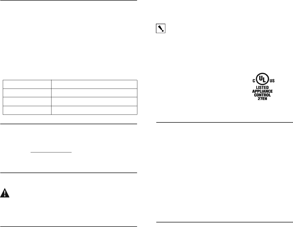
Underwriters Laboratories Inc.
This product has been tested by UL and found to
comply with:
•UL 244A, Third Edition, “Standard for Solid
State Controls for Appliances” UL 916, 3rd Edi-
tion, “Energy Management Equipment”
•CSA C22.2 No. 14-95, “Standard for Clock-Operated Switches”
Limited 1 Year Warranty
This device has a limited one (1) year warranty on parts from the date of
purchase. Control4 will replace or repair any defective unit. Return unit to the
place of purchase for replacement. For any damages incurred, the warranty
will never exceed the purchase price of the device. This warranty does not
cover installation, removal, or reinstallation cost. The warranty is not valid in
cases where damage was incurred due to misuse, abuse, incorrect repair, or
improper wiring or installation. It does not cover incidental or consequential
damage. This warranty gives you specific legal rights, and you might also be
entitled to other rights that vary from state to state. Some states do not allow
limitations on how long an implied warranty lasts or the exclusion or limitation
of incidental or consequential damages. In these cases, the above
mentioned limitations might not apply to you. For complete warranty
information, see www.control4.com. To automatically receive notification of
upgrades, return the enclosed registration card or register online at
www.control4.com.
About this Document
United States Patents Pending. Copyright © 2005-2006 Control4
Corporation. Control4 and the Control4 logo are registered trademarks of
Control4 Corporation. All trademarks are properties of their respective
owners. Part Number: 21-0160 Rev A Draft 10
LED Color Connection Status
Green Solid The device is on and drawing current.
Orange The device is learning current levels.
Red Solid Device is Off (no current).