Snap One TSG38C11 WiFi MiniTouch Screen Model TSG-3.8C1-(Color) User Manual MiniTS IG
Control4 WiFi MiniTouch Screen Model TSG-3.8C1-(Color) MiniTS IG
Snap One >
Exhibit 8
Mini Touch
Screen
Installation
Guide
Supported Models
Graphical Symbols in this Guide
The following symbols and their descriptions draw your attention to important
safe practices and additional information that can help you avoid injury, death,
or loss of material or time.
WARNING! This indicates a potentially hazardous situation that, if not avoided,
may result in death or serious injury. DO NOT IGNORE A WARNING!
CAUTION! This indicates a potentially hazardous situation that, if not avoided,
may result in minor or moderate injury. DO NOT IGNORE A CAUTION!
IMPORTANT! This indicates information that will help you avoid damage to
your equipment, loss of materials, or loss of time. PAY ATTENTION TO THESE
IMPORTANT STATEMENTS!
NOTE: This indicates a note on related information about the current topic.
TIP: This indicates a tip that might save you time or effort.
Important Safety Instructions
1. Read these instructions.
2. Keep these instructions.
3. Heed all warnings.
4. Follow all instructions.
5. Do not use this apparatus near water.
6. Clean only with dry cloth.
7. Install in accordance with the manufacturer’s instructions.
8. Do not install near any heat sources such as radiators, heat registers, stoves, or other
apparatus (including amplifiers) that produce heat.
9. Protect the power cords, if applicable, from being walked on or pinched particularly at
plugs, convenience receptacles, and the point where they exit from the apparatus.
10. Only use attachments/accessories specified by the manufacturer.
11. If applicable, unplug this apparatus during lightning storms or when unused for long
periods of time.
12. Refer all servicing to qualified service personnel. Servicing is
required when the apparatus has been damaged in any way, such as power-supply
cord or plug is damaged, liquid has been spilled or objects have fallen into the appara-
tus, the apparatus has been exposed to rain or moisture, does not operate normally,
or has been dropped.
WARNING! To reduce the risk of fire or electrical shock, do not expose this
apparatus to rain or moisture.
WARNING! To avoid bodily harm, always contact a Control4-authorized reseller
for assistance if any repair or adjustment is required.
CAUTION! Do not place unit near sources of heat or expose to direct sunlight
for an extended period of time.
IMPORTANT! Do not use pens or sharp objects to navigate or make selections
on the screen. To select an item or scroll through a list, use either your fingertip or
the Select Dial.
IMPORTANT! Improper use or installation can cause LOSS/DAMAGE OF
PROPERTY.
General Description
An essential component in every Control4 system is a user interface and
navigation method that allows users to communicate with the system. Along
with the Mini Touch Screen, Control4 offers a variety of other navigation options
for every room, including the System Remote Control, On-Screen (television),
10.5” Wireless Touch Screen, etc.
The Control4 Mini Touch Screen offers complete system control in an elegant
and compact design. The Mini Touch Screen is equipped with the touch screen,
an intuitive Select Dial, and a unique programmable shortcut button.
The Mini Touch Screen comes in two models: Ethernet and WiFi. These two
options are described in the following sections.
Mini Touch Screen Placement for both models: Place the Mini Touch
Screen in a convenient location at eye level, typically near the entrace of the
room, approximately 57 to 61 inches from the floor. Note that for the Wireless
model, you need to place it near a power source, such as at an outlet, or be
able to route AC power to it.
Option 1: Ethernet Model
The Ethernet Mini Touch Screen requires a Power over Ethernet (PoE) device
that injects electrical current into the Ethernet cable in order to provide the
Ethernet Mini Touch Screen with both power and a network connection. See
Figure 1. The Ethernet Mini Touch Screen works with the Control4 Power Over
Ethernet Injector (model # AC-POE1-B) or a third-party PoE injector or switch.
If you plan to use a third-party PoE solution or a non-standard connection
cable, refer to “Power Interface Requirements” for the specifications.
Ethernet Placement: Place the PoE Injector near your gateway/router/switch.
Pull the Ethernet cable from that location to the location of where you want to
place your Mini Touch Screen.
FIGURE 1. Ethernet Model - Requires Ethernet Wiring to Mini Touch Screen.
Option 2: WiFi Model
The WiFi Mini Touch Screen differs from the Ethernet model in two ways:
•It uses a WiFi antenna that communicates via WiFi to a Wireless
Access Point to the Control4 Controller, such as the Home Theater
Controller.
•It gets its power from an AC power source close to the Mini Touch
Screen. This power connection requires both neutral and hot connec-
tions. See Figure 2.
WiFi Placement: Place the WiFi Model above a power source, such as at an
outlet. Ensure you have WiFi in the home.
FIGURE 2. WiFi Model - Requires AC power to Mini Touch Screen.
IMPORTANT! If you already have a network setup distributing DHCP, manually
disable any DHCP service on any device you add prior to putting it on the
network, such as a wireless router. You cannot have two devices running DHCP
or this may result in devices malfunctioning. For information about setting up a
home network, see Composer online help topic: “Guidelines for Setting up a
Wired or Wireless Network.”
Wall Box Kit Options
There are four wall box options to install the Mini Touch Screen. Metal and
plastic wall boxes are available for new or retrofit versions. The following
diagrams show the available wall mounting kits.
FIGURE 3. Mini Touch Screen/LCD Keypad Wall Box Kits - New Construction
FIGURE 4. Mini Touch Screen/LCD Keypad Wall Box Kit - Retrofit (includes wall
box template)
What’s in the Box
Carefully unpack the contents from the box and make sure the following items
are included in the box. If any item is missing or damaged, please contact your
Control4-authorized reseller immediately.
•Control4 Mini Touch Screen
•Warranty card
•Mini Touch Screen Installation Guide (this document)
•Mini Touch Screen User Guide
•Two sheet metal screws (1/2 inch) for attachment to a plastic wall box.
(Metal wall boxes require machine screws. They are included with the
the metal wall box kit.)
Requirements
To install the Mini Touch Screen, you need the following:
•Home Theater Controller or Media Controller fully installed and config-
ured with a Control4 system.
•(Optional) An amplifier or amplified speakers.
•(Optional) Any RCA cables required to connect the Mini Touch Screen
and the amplifier or amplified speakers.
•Ethernet only:
• Ethernet network installed and available that includes a gateway/
router/switch.
• Control4 PoE Injector (model #AC-POE1-B) or another third-party PoE
injector or switch.
• Two Ethernet Category 5 cables to support your PoE injector: (1) one
that will run from the Ethernet gateway/router/switch to the PoE
injector/switch and (2) one that will run from the PoE injector/switch to
the Ethernet Mini Touch Screen wall box.
•WiFi only:
• Wireless network (WiFi 802.11b/g) installed and available that includes
a wireless access point (WAP).
• Access to in-wall AC power. (A neutral connection is required).
• 14 AWG electrical wire long enough to pull between Mini Touch
Screen and power source.
•Control4 Mini Touch Screen/LCD Keypad custom wall box kit. See
“Wall Box Kit Options.”
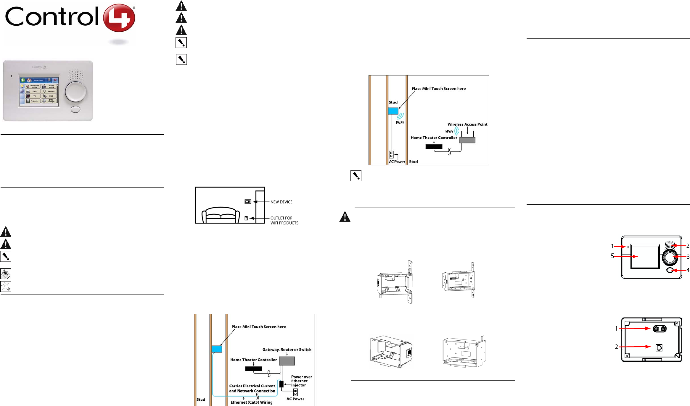
Front and Rear Panel Description
Front View
1. Microphone: (Future) Microphone
for communication features.
2. Speaker: (Future) Speaker for inter-
com.
3. Select Dial: Use during setup to iden-
tify the device to the Control4 system.
Once setup is complete, for scrolling
through displays.
4. Shortcut Button: For custom pro-
gramming to initiate an action or
sequence of actions.
5. Display: 3.8" TFT (3.5” viewing area), Touch-Screen with 320x240 Resolution,
QVGA.
Back View: Ethernet Model
1. RCA audio line-level output:
(Optional) Connect these ports to an
amplifier or amplified speakers for audio
output using a standard RCA stereo
cable.
2. RJ-45 port: For connection to the Ether-
net PoE source to power the device and
provide network communication.
3. Dimension: Front - 6 1/2” (W) x 4 3/8”
(H) x 1/5-2/5” (D)
4. In-Wall - 5 7/8” (W) x 3 5/8” (H) x 1 1/2”
(D)
5. Power Supply: PoE (Power Over Ethernet).
Ethernet Models:
TSE-3.8C1-W (White)
TSE-3.8C1-B (Black)
TSE-3.8C1-A (Almond)
WiFi Models:
TSG-3.8C1-W (White)
TSG-3.8C1-B (Black)
TSG-3.8C1-A (Almond)
Plastic model # AC-NWB3.8-G Metal model # AC-NWB3.8-M
Plastic model # AC-RWB3.8-G Metal model # AC-RWB3.8-M
Back View: Wireless Model
1. RCA line-level audio output:
(Optional) Connect these ports to
an amplifier or amplified speakers
for audio output using a standard
RCA stereo cable.
2. AC Wires: Connect the black
(hot) and white (neutral) wires
from the back of the Mini Touch
Screen to the hot and neutral
wires from the wall.
3. Dimension: Front - 6 1/2” (W) x 4
3/8” (H) x 1/5-2/5” (D)
4. In-Wall: 5 7/8” (W) x 3 5/8” (H) x 1 1/2” (D)
5. Power Supply: AC Power
6. Network Support: WiFi IEEE 802.11b/g
Installation
WARNING! For the location where you are installing the Mini
Touch Screen, switch off the circuit breaker or remove the fuse
from the fuse box.
IMPORTANT! For new or retrofit, when cutting the opening for
the wall box, DO NOT cut the opening too large. Be conservative and cautiously
enlarge it as needed because there is not as much overhang on the faceplate of
the Mini Touch Screen as you are accustomed to with standard switch and outlet
plates.
IMPORTANT! Before you can complete the installation instructions for the Mini
Touch Screen, you must have a Control4 Mini Touch Screen\LCD Keypad Wall
Box installed according to the documentation provided in the wall box kit.
NOTE: The table top Mini Touch Screen model is sold assembled. These
installation instructions do not apply.
1 Prepare wall for installation.
For Ethernet Model: Install a PoE injector or switch. To do this:
a. Connect the Control4 PoE Injector to a power source,
such as an AC outlet, using the 2-prong power cord
(provided with the unit). The light comes on when
power is applied.
b. Connect one of the RJ-45 LAN ports on the gateway/
router/switch to the PoE Injector’s LAN port using the RJ-45 ethernet
cable. The STAND BY light on the PoE Injector lights up.
c. Connect the PoE Injector’s PWR LAN-OUT port to the Ethernet Mini
Touch Screen using the RJ-45 ethernet cable in the wall. The Power
mode LED will change from orange to green.
For Wireless Model: Connect wires to AC Power Source for Wireless
Model. To do this:
a. Connect the black (hot) and white (neutral) wires from the back of
the Mini Touch Screen to the hot and neutral wires from the wall.
b. Cap the ground wire from the wall if you are using a plastic wall box.
If you are using a metal wall box, attach the ground wire to the box at
the location designated by the ground symbol.
2 (Optional) If you intend to send audio to an amplifier or amplified
speakers, route a stereo RCA cable from your Mini Touch Screen audio
out ports (RCA red and white connectors) to your amplifier or amplified
speakers.
3 With the screws provided, attach the
Mini Touch Screen base at the top-left
and bottom-right corners of the wall box
(as shown).
4 Hook the tabs on the left underside of
the faceplate onto the lip of the base on
the left-hand side. Then close the
faceplate over the top of the base from
left to right, feeding the Select-Dial post through the corresponding hole in
the faceplate.
5 Install the washer and the nut to hold the faceplate in place.
IMPORTANT! Tighten the nut by hand. Do not overtighten. Excessive force will
permanently damage the rotary device and void the warranty.
6 Install the Select Dial on the post.
IMPORTANT!
TIP: You need to calibrate your Mini Touch Screen: the first time you use it or any
time the system requests it. When the device needs calibration, the on-screen
instruction will prompt you to calibrate the device. To do this, use your fingertip to
touch the screen firmly and accurately at the point indicated by the crosshairs.
Repeat for each of the four subsequent points indicated by the crosshairs
NOTE: While you may use a stylus (a smooth pointing device that is sold with
many hand-held electronic devices) with this device, the use of a stylus is not
necessary or recommended. Instead, use your fingertips or the Select Dial to
scroll through lists and make selections.
NOTE: To protect the display screen of your device: (1) Use one of the screen-
saver options available from the Info > Config > Screen Saver page; (2) Use a
plastic (cling-on) screen protector (available where hand-held electronic devices
are sold) to help guard against scratches.
7 (For WiFi Model only) From the WiFi Mini Touch Screen, configure a
wireless access point:
a. Press Info > Wireless > Wireless. The Wireless configuration
screen appears.
b. Press Add to add the WiFi Mini Touch Screen as a wireless device.
c. Press in the Network (SSID) text box to enter the SSID. A virtual
keypad displays for you to enter the information.
d. Press the WEP button, then enter the WEP key in hex in the text
box. A virtual keypad displays for you to enter the information. Press
OK when finished.
e. Highlight the SSID of the WiFi Mini Touch Screen and press Enable.
f. Press OK.
8 Now that your Mini Touch Screen is physically installed and appearing on
the home network, you can add it to the Control4 System using the
Composer software (available for your PC). See Composer online help for
information on how to add the Mini Touch Screen and other devices to the
Control4 System.
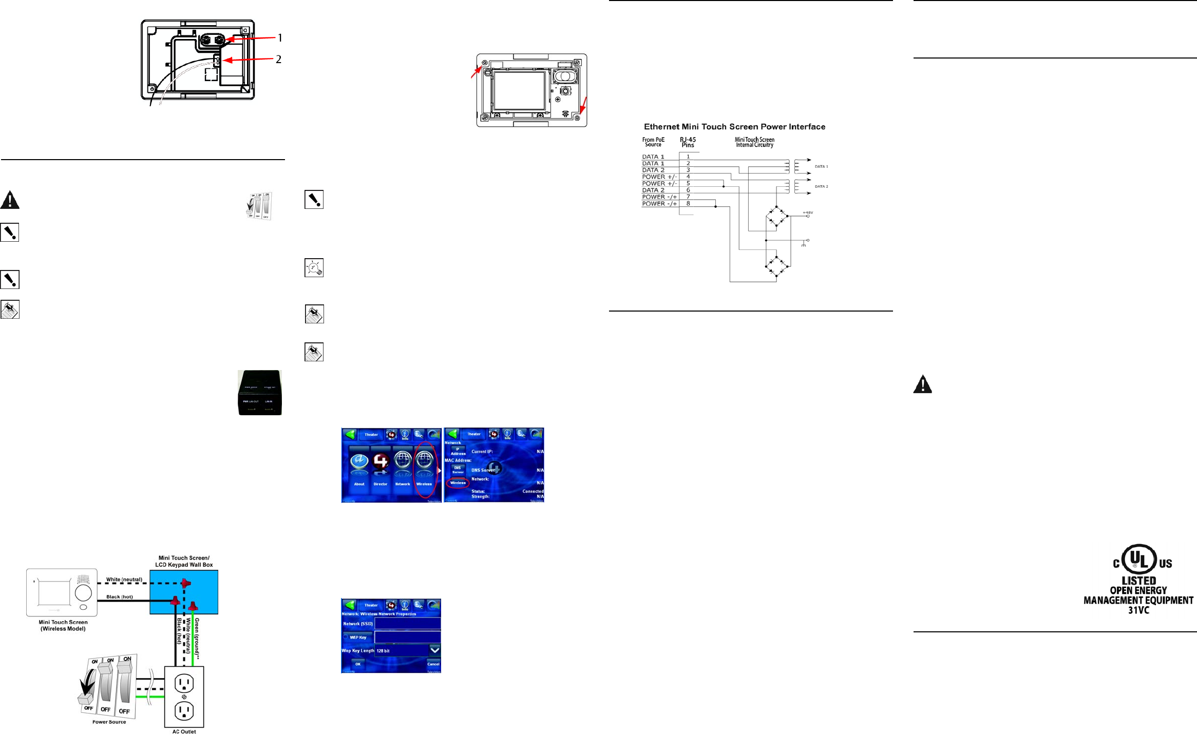
Power Interface Requirements
If you plan to use any other PoE solutions besides the Control4 PoE Injector,
such as a third-party injector or PoEswitch, then refer to the diagram of the
Ethernet Mini Touch Screen Power and Connection Schematic scematic to
determine how to create a PoE solution and cabling to meet the power and
connection requirements for Mini Touch Screen.
Ethernet Mini Touch Screen Power and Connection Schematic
Troubleshooting
If you experience operational problems with the Control4 Mini Touch Screen,
check the following list for system troubleshooting. If problems persist, contact
your authorized Control4 dealer for technical support.
Question: What if the on-screen display that reads “Welcome to
Navigator” won’t go away?
Answer: If screen also has text that reads “Touch the crosshairs firmly...,”
then you need to calibrate the device as described in the installation
instructions.
Question: What if my Mini Touch Screen locks up or runs slowly?
Answer: Try rebooting by holding down the Select Dial for ten seconds.
Reset the system by cutting and restoring power: for Ethernet model,
disconnect and reconnect the PoE connector at the network gateway,
router or switch.
Question: What if my Mini Touch Screen is damaged?
Answer: Contact your Control4-authorized reseller.
Question: What if I have network connection problems?
Answer: Make sure the network cable connectors are firmly locked into the
network jack. See Composer online topic: “Guidelines for Setting up a
Wired or Wireless Network.”
Question: What if my Mini Touch Screen is unresponsive to the touch?
Answer 1: The nut under the Select Dial may be too tight. This can cause
the faceplate to press against the overlay causing a false “press and hold”
and renders the touch overlay inoperable. To fix this, loosen nut until proper
operation is restored.
Answer 2: The lower-right display clip may be wedged between the overlay
and the display. (It is one of seven clips that hold the display in place.) Do
NOT use any metal or sharp objects to correct this. (1) Using your left
thumb, press down firmly on the lower edge of the display to the left of the
clip. (2) Using your right index finder in a hook-shape, slide your fingernail
under the clip to allow the display to slide back under the clip.
Answer 3: The Mini Touch Screen may need to be recalibrated. Call
technical support for further information on this procedure.
Warranty
See Mini Touch Screen User Guide for warranty information.
Regulatory Compliance
This product complies with standards established by the following regulatory
bodies:
Federal Communications Commission (FCC)
Industry Canada
Underwriters Laboratories Inc. (UL)
FCC Interference Statement
This equipment has been tested and found to comply with the limits for a Class
B digital device, pursuant to Part 15 of the FCC Rules. These limits are
designed to provide reasonable protection against harmful interference in a
residential installation. This equipment generates, uses, and can radiate radio
frequency energy and, if not installed and used in accordance with the
instructions, may cause harmful interference to radio communications.
However, there is no guarantee that interference will not occur in a particular
installation. If this equipment does cause harmful interference to radio or
television reception, which can be determined by turning the equipment off and
on, the user is encouraged to try to correct the interference by one or more of
the following measures:
•Reorient or relocate the receiving antenna.
•Increase the separation between the equipment and receiver.
•Connect the equipment into an outlet on a circuit different from that to
which the receiver is connected.
•Consult the dealer or an experienced radio/TV technician for help.
FCC Caution
IMPORTANT! Any changes or modifications not expressly approved by the
party responsible for compliance could void the user's authority to operate the
equipment.
This device complies with Part 15 of the FCC Rules. Operation is subject to the
following two conditions: (1) This device may not cause harmful interference,
and (2) this device must accept any interference received, including
interference that may cause undesired operation.
Industry Canada Statement
This Class B digital apparatus complies with Canada ICES-003.
Cet appareil numérique de la classe B est conforme à la norme NMB-003 du
Canada.
Underwriters Laboratories Inc. (UL)
This product has been tested by UL and has
been found to be in compliance with:
UL 916:1998: Standard for Energy
Management Equipment
About this Document
United States Patents Pending. Copyright © 2004-2005 Control4 Corporation.
Control4 and the Control4 logo are registered trademarks of Control4
Corporation. All trademarks are properties of their respective owners. Part
Number: 21-0120 Rev B