Societa Per L Elettronica s r l 1K-FA Linear amplifier for radio amateur use User Manual Exhibit6 Manuale
Societa' Per L'Elettronica s.r.l. Linear amplifier for radio amateur use Exhibit6 Manuale
UserManual.wiki
>
Societa Per L Elettronica s r l
>
1K FA User Manual
Users Manual
Navigation menu
Upload a User Manual
Namespaces
Wiki Guide
HTML
PDF
Info
Views
User Manual
Discussion / Help
Navigation


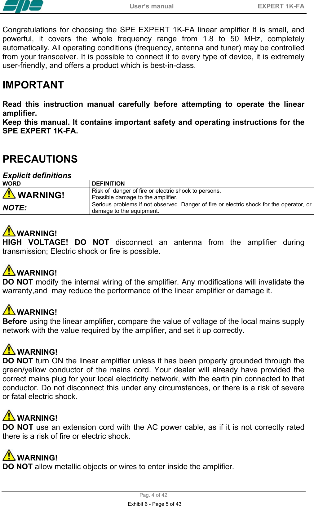
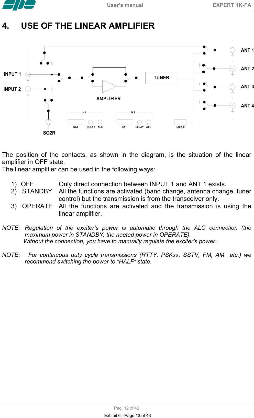
![User’s manual EXPERT 1K-FA Pag. 5 of 42 WARNING! DO NOT obstruct the entries for cooling air at both the sides of the amplifier. Ensure that no object impedes the correct operation of the fans. WARNING! DO NOT expose the linear amplifier to rain, snow or any liquids. WARNING! DO NOT instal the linear amplifier in a place without good ventilation. This could limit heat dissipation and the amplifier could be damaged. WARNING! DO NOT touch the amplifier with damp or wet hands. There is danger of electric shock. Avoid opening it before you have disconnected it from the mains supply, then wait at least 2 minutes for electrolytic capacitors to complete their discharge. To clean the amplifier DO NOT use chemical agents like alcohol or benzene because the plastic surfaces could be damaged. AVOID using the amplifier in areas with temperatures below –10° C (+14°F) or above +40°C (+104°F). AVOID using the linear amplifier in locations that are very dusty, damp or in direct sunlight. AVOID placing the linear amplifier against walls, the circulation of the air would be obstructed and the noise of the fans would be reflected toward the operator. AVOID permitting children to play with the amplifier. If you do not use the linear amplifier for long time, set the back main switch [I/O] to the OFF position [O]. This amplifier should only be operated by persons who have an appropriate radio transmitting licence, and you should observe your licence conditions whilst using it. Exhibit 6 - Page 6 of 43](https://usermanual.wiki/Societa-Per-L-Elettronica-s-r-l/1K-FA/User-Guide-751315-Page-6.png)
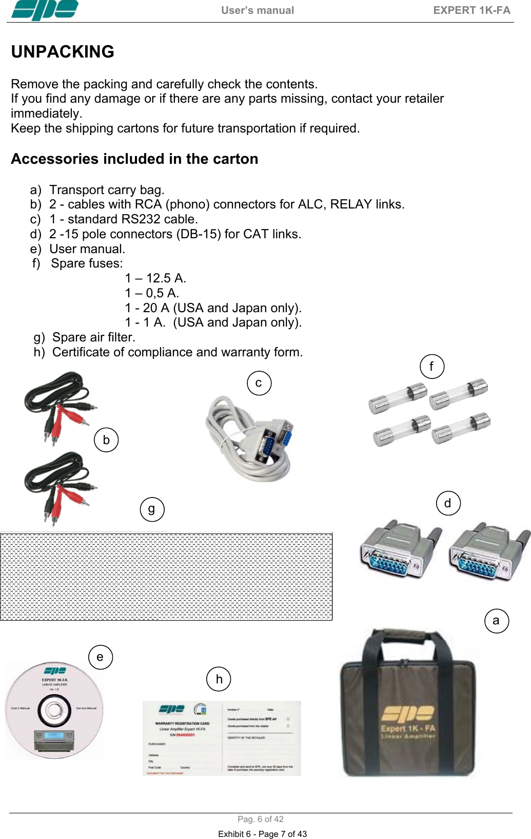
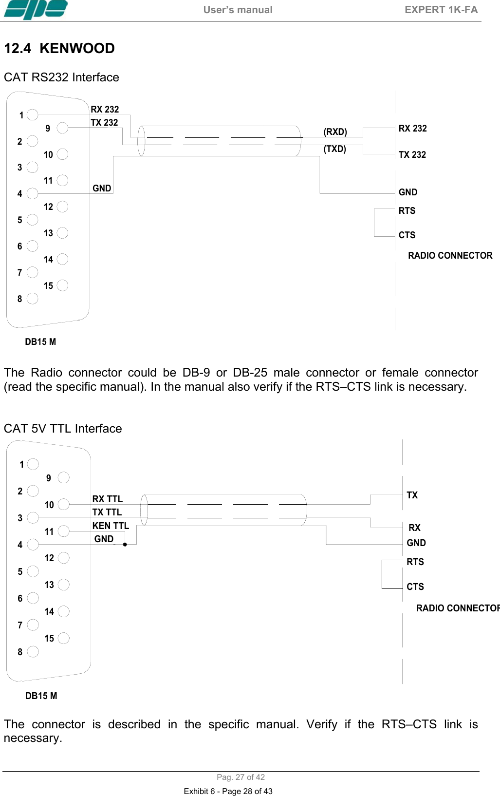
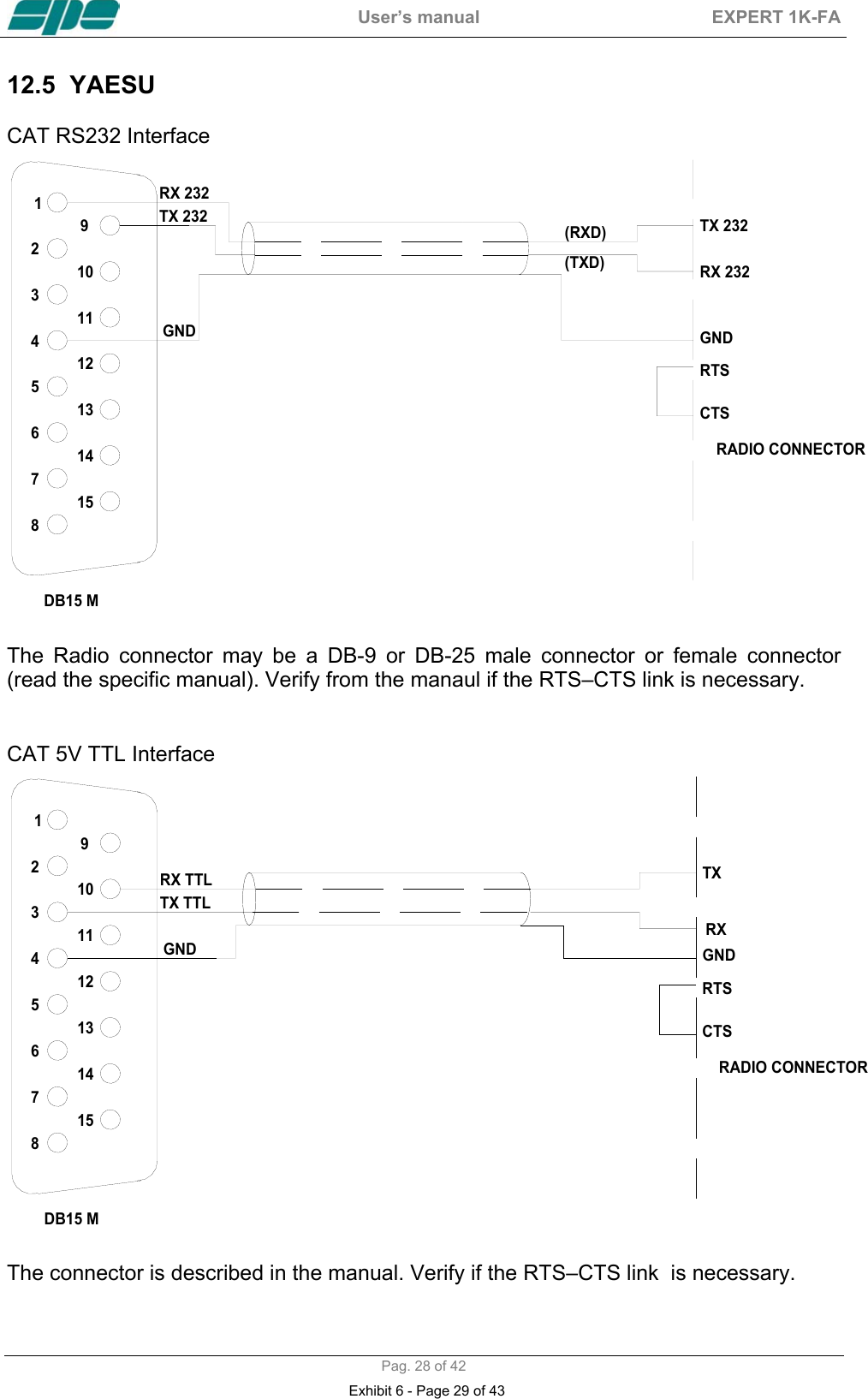
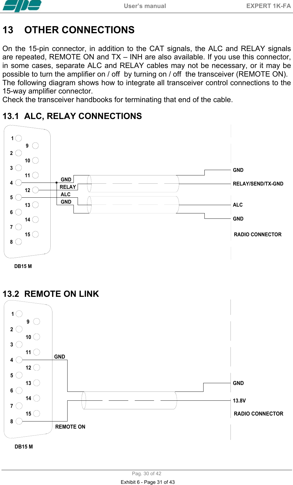
![User’s manual EXPERT 1K-FA Pag. 9 of 42 2. GENERAL INFORMATION (Read the specific chapters for more details). 2.1 Power supply The amplifier’s power supply is 230 / 115 Vac (230 Vac default). The main switch [I/O] is located on the rear panel, in the [O] position all the internal circuitry is powered off, in the [I] position (red led ON) it is possibile turn ON or turn OFF the linear amplifier in one of the following ways: a) Using the [ON] /[ OFF] keys on the front panel. b) Applying / removing 9 -15 Vdc on pin (8) of the CAT connector. c) Using the RS232 port and the management software. It is possible to download this software from the website www.linear-amplifier.com . NOTE: When turned ON, almost all transceivers output 13,8 Vdc. With this voltage, the linear amplifier can be turned automatically ON / OFF at the same time as the transceiver. 2.2 Input / Output The linear amplifier has two inputs (INPUT 1, INPUT 2) to which it is possible to connect two transceivers of any brand or type. These inputs are selected with the [INPUT] key. It can manage up to four antennas (ANT 1, ANT 2, ANT 3, ANT 4). The amplifier selects antennas automatically when they have been programmed. 2.3 ALC / RELAY / CAT There are two transceiver inputs (IN 1, IN 2), to allow two different transceivers to be connected at the same time. ALC Is a voltage (0, -11 Vcc) generated by the amplifier, it is used to control the output power of the transceiver. In this way the power from the amplifier may be automatically controlled. This link is recommended. If the ALC port is not connected, it is ncessary to manually regulate the drive power from the transceiver. RELAY This essential link allows the amplifier to be put in the transmit state. To do that it is necessary that the inner pin of the phono connector is connected to signal ground. This is normally done at the transceiver with either a close on ground relay, or with a switching transistor. It is important that the voltages at that terminal do not exceed 12 Vdc. On the transceiver this link is often called SEND or TX GND. Refer to your transceiver manual for more details. CAT Thanks to this link the linear amplifier will detect the operating frequency of the transceiver and then automatically control changes of band, antenna and automatic antenna tuner. Most modern tranceivers have CAT control. In old models often, analog or digital information are sent for changing band. The SPE Expert 1K-FA, thanks to an efficient frequency counter, constantly controls and verifies data coming from the transceiver. Automatic management of bands, antennas and tuner can be done in the following way: Exhibit 6 - Page 10 of 43](https://usermanual.wiki/Societa-Per-L-Elettronica-s-r-l/1K-FA/User-Guide-751315-Page-10.png)
![User’s manual EXPERT 1K-FA Pag. 16 of 42 8. TUNER The amplifier has an automatic tuner that handles load mismatches up to 3:1 VSWR (2,5:1 for 50 MHz). The circuit used is a PI – L network with excellent harmonic suppression. The amplifier contains a look-up table with all the permitted bands. For tuner management, antenna data and other working data are stored. Every band has a sub-band set, and for each of those, data related to the antenna and auto-ATU tuning is stored. The CAT and the frequency counter detect the operating frequency and the correct sub-band. Thanks to the stored data, the tuner and the antenna are automatically set correctly. For every input there is a different table. If two exciters are connected at the same time, each exciter can have different configurations. It is possible to use the two different tables when the amplifier operates at two different locations. In fact it is possible to use the INPUT 1 at one and INPUT 2 on the other. In this way repeated reprogrammings are not needed In the US version, operation on the 12 m and 10 m bands has been inhibited following FCC regulations. Authorized 12/10m operation of the amplifier by licensed radio amateurs will be enabled by the dealer there in accordance with current rules. The auto-tuner and antenna selection via the amplifier are still enabled even in 12/10m inhibited units. All auto-tuner functions remain, on standby, whilst using the transceiver only. Setting of the match data to write in the tables is performed automatically by pressing the [TUNE] key The system will then find the correct match for minimum SWR. To achieve a better match than that achieved with the automatic tune routine (most unlikely) it is possible to set the tuning manually by using the keys [◄ C], [C ►], [◄ L], [L ►]. When manual tuning has been performed, it is possible to read the tuning value, the working frequency and the associated sub-band on the appropriate screen page. Both the types of tuning are always effected in “STANDBY“ state. NOTE: The tuner, like all analog circuits, introduces a loss (0,8 dB max.) that may vary with tuning conditions.The power meter of the amplifier does not show this loss as the power is measured at the tuner input where the load resistance is always constant (50 ohm). NOTE: ATTENTION, When the amplifier is on the ‘STANDBY’ or ‘OPERATE’ modes, always disable the automatic tuner in your transceiver. Exhibit 6 - Page 17 of 43](https://usermanual.wiki/Societa-Per-L-Elettronica-s-r-l/1K-FA/User-Guide-751315-Page-17.png)
![User’s manual EXPERT 1K-FA Pag. 17 of 42 9. PROTECTIONS / ALARMS The SPE 1K-FA has a sophisticated protection system that constantly controls the amplifier’s most important parameters. These parameters are: Temperature of the heatsink; max. / min. voltage on the PA; max. PA current; SWR; reflected power; max voltage RF on the tuner; input power; power combiner balance. NOTE: Unlike all the other linear amplifiers that measure only the reflected power of the antenna, to guarantee a greater protection of the PA, the SPE amplifier measures also the power of harmonics reflected by the band-pass filter. NOTE: To guarantee the maximum efficiency with the same output power, the PA has three MRF150 push-pull amplifiers connected through a combiner. NOTE: Temperature measurement is used also to control fan speed. The thresholds where the speed changes may be changed from NORMAL (default) or CONTEST (See the “Programming” chapter of this manual). The protection system is effected in two different ways: 1) Through hardware circuits to guarantee minimum intervention time. 2) Through software, with one of the two CPU’s, to guarantee the maximum precision. The two results are always compared, every difference produces a protection trip and consequent alarm. There are three types of protections/alarms: a) SIMPLE This is the most common case. An acoustic warning beep sounds, but no operator intervention is required, as the control system automatically restores the correct operating conditions. b) SERIOUS When automatic system recovery is not possible (e.g. the temperature climbs over the limits due to obstruction of the fans, SWR is too high, etc.). In this case the amplifier switches into standby state and the alarm is stored. Normally transmission can continue with the exciter only. c) FATAL If the amplifier is in the b) situation but the CPU is faulty or it isn’t able to operate, the amplifier is turned OFF with no other warning. To restart the amplifier, the main switch in the rear panel has to be set first to [O], and then to the [I] position NOTE: It is possibile to read the alarms file log in the standby state using the [DISPLAY] key. To reset the alarm file log press the [TUNE] and [OPERATE] keys together. NOTE: If the acoustic alarm is very frequent during transmission, the possible causes should be investigated. Exhibit 6 - Page 18 of 43](https://usermanual.wiki/Societa-Per-L-Elettronica-s-r-l/1K-FA/User-Guide-751315-Page-18.png)
![User’s manual EXPERT 1K-FA Pag. 18 of 42 NOTE: Before the temperature limits are reached, the output power will change from FULL to HALF automatically, so that transmission with the amplifier may continue with reduced power. In SSB the use of the compressor, only when necessary, strongly reduces the increase of the temperature. If the temperature is allowed to rise further, then a “SERIOUS“ alarm will eventually be activated. NOTE: During a SERIOUS alarm, there is an acoustic alarm for 30 sec. Pressing the [DISPLAY] key, the system changes to ‘STANDBY’ state immediately. Exhibit 6 - Page 19 of 43](https://usermanual.wiki/Societa-Per-L-Elettronica-s-r-l/1K-FA/User-Guide-751315-Page-19.png)
![User’s manual EXPERT 1K-FA Pag. 19 of 42 10. PROGRAMMING The three [SET], [◄▲] and [►▼] keys, underlined with an orange line, permit programing the amplifier and they can used in the following way: [SET] Use it to open the menu page, to validate the choices and to exit from the menu page. [◄▲], [►▼] Use these to select the options. A green led illuminates during the programming process. To program the system is very easy. You will find your programming choices confirmed by the items shown at the lower part of the display. NOTE: Programming is only possible in ‘STANDBY’ mode. NOTE: Programming changes take effect only after exiting from the menu page (the green led extinguishes). 10.1 Ways to operate Pressing the [SET] key opens the menu page. On the display there are the following options: a) ANTENNA An appropriate antenna may be assigned to each band selecting the (ANT 1, ANT 2, ANT 3, ANT 4) connector. If you don’t have an antenna for a particular band, input “NONE“. Exhibit 6 - Page 20 of 43](https://usermanual.wiki/Societa-Per-L-Elettronica-s-r-l/1K-FA/User-Guide-751315-Page-20.png)
![User’s manual EXPERT 1K-FA Pag. 21 of 42 c) MANUAL TUNE Allows you to tune the amplifier manually. However, achieving a better setting than that obtained by automatic tuning is very unlikely. Set your exciter to transmit a continuous RTTY or CW signal. Press the [◄ L], [L ►], [◄ C], [C ►] keys until you obtain the minimum SWR. The operating frequency and the sub-band are also shown on the display. NOTE: The tuning process has to be repeated for every entry (INPUT1, INPUT 2). d) BACKLIGHT Regulates the backlight of the display. NOTE: Display contrast has to be set manually. Remove the upper cover and adjust through the hole at the upper right of the CPU card. Adjust only if it is necessary, and use an insulated screwdriver with care. e) CONTEST Permits programming two fan thresholds for normal operation (Normal) and heavy-use (Contest). off : Normal (65 °C, 75 °C). on : Contest (60 °C, 70 °C). f) BEEP on : All acoustic warnings alarms operate and a beep confirms a keystroke. off: When you press a key there is no beep feedback, but for all warning conditions and alarms, the acoustic warnings are still functional. Exhibit 6 - Page 22 of 43](https://usermanual.wiki/Societa-Per-L-Elettronica-s-r-l/1K-FA/User-Guide-751315-Page-22.png)
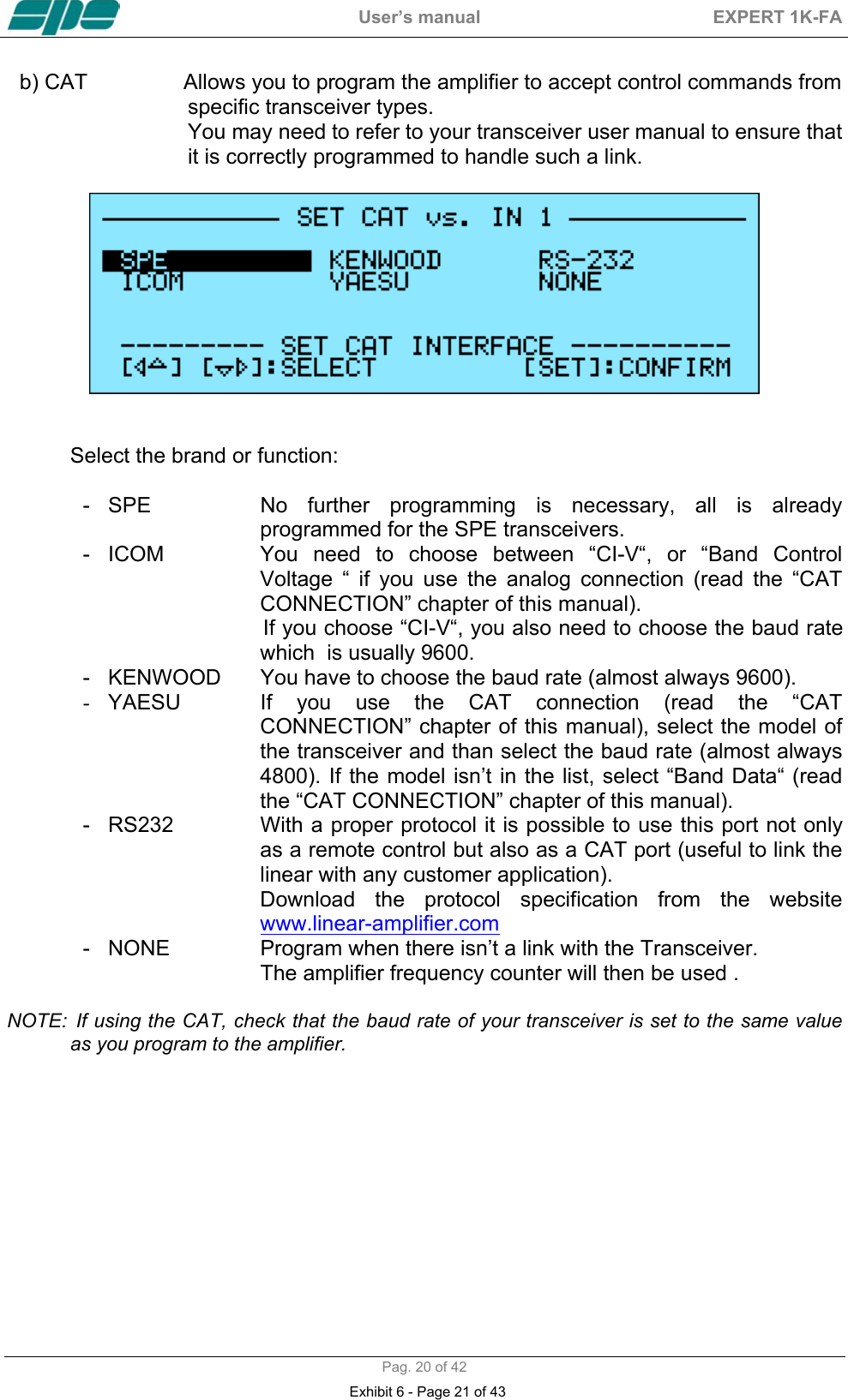
![User’s manual EXPERT 1K-FA Pag. 22 of 42 11. INITIAL OPERATION OF THE AMPLIFIER Before turning ON the amplifier, the following preliminary operations are necessary: 1) Read this manual with care. 2) Be sure that the amplifier is correctly set for the local mains voltage supply. 3) Connect the linear to ground circuit 4) Connect the antennas. 5) Connect the amplifier to the transceiver (read the “CONNECTIONS WITH THE TRANSCEIVER” chapter of this manual) Operate [I] the main switch on back panel, and press the [ON] key on the front panel. Select the INPUT for the transceiver, and always carry out programming with the amplifier in STANDBY. If you change INPUT you have to repeat this programming. NOTE: You may have to repeat some programming if you change antenna, transceiver,etc. NOTE: ATTENTION the ‘RELAY’ and ‘CAT’signals in some types of transceivers are only turned ON from a transceiver MENU. Refer to the user manual. NOTE: ATTENTION, when the amplifier is on the ‘STANDBY’ and ‘OPERATE’ modes, always disable the transceiver auto-ATU. 11.1 Initial Programming You must carry out the next steps in the sequence below: a) Set Antenna. Press [SET] and open the “ANTENNA“ menu page. Assign an appropriate antenna for the band concerned. If you don’t have an antenna for a band, input “NONE“. When all the antennas are programmed, exit and go back to STANDBY. To verify the correctness of the programming, press the [ANT] key, the band / antenna programmed will be shown. b) Set CAT. Press [SET] and enter the “CAT“ menu page. Select the transceiver brand and progress with programming according to the type of connection between the amplifier and the transceiver (read the “CAT CONNECTIONS” chapter of this manual). At the end of programming, exit and go back in STANDBY. To verify the correctness of programming, press the [CAT] key, and all the data stored will appear on the display. To verify the correct “CAT” operation, press [SET] and select “MANUAL TUNE”, While changing your transceiver VFO, you should see the amplifier frequency display follow. Then return to STANDBY. Exhibit 6 - Page 23 of 43](https://usermanual.wiki/Societa-Per-L-Elettronica-s-r-l/1K-FA/User-Guide-751315-Page-23.png)
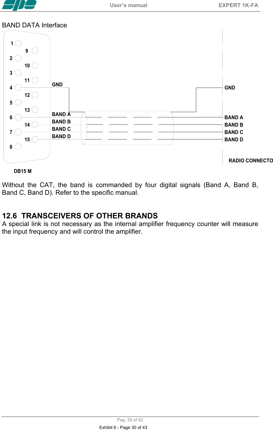
![User’s manual EXPERT 1K-FA Pag. 23 of 42 In the same way, if “BAND CONTROL VOLTAGE“ or “BAND DATA“ are connected, check that the amplifier follows band changes at the transceiver. If it does not, verify that your programming (or your link) has been done correctly. d) Use of Automatic Tuner To complete the programming it is necessary to match the antennas to the amplifier by operating “TUNE“ (read the “TUNER“ chapter of this manual). We recommend you to select each band (with available antenna) and then program the tuner for the sub-bands within which you will operate. Refer to the table in section 18 of this manual to select the appropriate sub-bands for your operating preferences. Progress as follows: 1) Find the central frequency of the sub-band to tune in the table (refer to section 18 of this manual) and set the transceiver to that frequency. 2) Press the [TUNE] key. 3) Set your transceiver to transmit a continuous tone in RTTY or CW. The procedure for automatic tuning will start and then it will stop when SWR is at a minimum. Sometimes it is possible to improve tuning by pressing the [TUNE] key again. 4) Repeat the previous steps for all bands and sub-bands you want. NOTE: If the ALC link is not used, it is preferable to reduce the transceiver power to about 50 Watts during this operation. NOTE: As a default, the table is programmed for standard 50 ohm out. If, for a band, you want to reset to default programming,progress as follows: - Go to the “ANTENNA“ menu page and set this band to “NONE“, then exit from that page. - Go to the “ANTENNA“ menu page again, assign the appropriate antenna to this band, then exit from that page. The programming will be reset for 50 ohm output. The initial programming concludes after steps a), b), c). 11.2 Operating You need few precautions when using the amplifier thanks its high level of automation. SPE reminds you that it is better to lose a fraction of dB in transmitted power, by slightly reducing the drive power, than to over-drive the amplifier and have a poor quality transmission. During transmission check the parameters on the display always, because SPE has selected, designed and adjusted them with care. SPE recommends (using the ALC link) that the transceiver should be set to its maximum drive power. To reduce the amplifier output, if required, it is then necessary only to set the amplifier to “HALF” power state rather than changing the transceiver drive power. Of course you may also regulate continuously the amplifier output power by changing the level of drive power from your transceiver. If less output power than 500 Watts is desired, it is preferable, for best efficiency, to start to reduce drive from the “HALF” power state. Exhibit 6 - Page 24 of 43](https://usermanual.wiki/Societa-Per-L-Elettronica-s-r-l/1K-FA/User-Guide-751315-Page-24.png)
![User’s manual EXPERT 1K-FA Pag. 39 of 42 18. TABLE BAND TABLE, SUB-BAND, CENTRAL FREQUENCY SUB-BAND [ 0] 1785 [ 1] 1795 [ 2] 1805 [ 3] 1815 [ 4] 1825 [ 5] 1835 [ 6] 1845 [ 7] 1855 [ 8] 1865 [ 9] 1875 [ 10] 1885 [ 11] 1895 [ 12] 1905 [ 13] 1915 [ 14] 1925 [ 15] 1935 [ 16] 1945 [ 17] 1955 160 m [ 18] 1965 [ 19] 1975 [ 20] 1985 [ 21] 1995 [ 22] 2005 [ 23] 2015 [ 24] 3470 [ 25] 3490 [ 26] 3510 [ 27] 3530 [ 28] 3550 [ 29] 3570 [ 30] 3590 [ 31] 3610 [ 32] 3630 [ 33] 3650 [ 34] 3670 [ 35] 3690 [ 36] 3710 [ 37] 3730 [ 38] 3750 [ 39] 3770 [ 40] 3790 [ 41] 3810 [ 42] 3830 [ 43] 3850 [ 44] 3870 [ 45] 3890 [ 46] 3910 [ 47] 3930 80 m [ 48] 3950 [ 49] 3970 [ 50] 3990 [ 51] 4010 [ 52] 4030 [ 53] 6963 [ 54] 6988 [ 55] 7013 [ 56] 7038 [ 57] 7063 [ 58] 7088 [ 59] 7113 [ 60] 7138 [ 61] 7163 [ 62] 7188 [ 63] 7213 [ 64] 7238 40 m [ 65] 7263 [ 66] 7288 [ 67] 7313 [ 68] 7338 30 m [ 69] 10075 [ 70] 10125 [ 71] 10175 [ 72] 13975 [ 73] 14025 [ 74] 14075 [ 75] 14125 [ 76] 14175 [ 77] 14225 20 m [ 78] 14275 [ 79] 14325 [ 80] 14375 17 m [ 81] 18075 [ 82] 18125 [ 83] 18165 [ 84] 20975 [ 85] 21025 [ 86] 21075 [ 87] 21125 [ 88] 21175 [ 89] 21225 15 m [ 90] 21275 [ 91] 21325 [ 92] 21375 [ 93] 21425 [ 94] 21475 12 m [ 95] 24891 [ 96] 24963 [ 97] 25038 [ 98] 27950 [ 99] 28050 [100] 28150 [101] 28250 [102] 28350 [103] 28450 [104] 28550 [105] 28650 [106] 28750 [107] 28850 [108] 28950 [109] 29050 [110] 29150 [111] 29250 [112] 29350 [113] 29450 [114] 29550 [115] 29650 10 m [116] 29750 [117] 49750 [118] 50250 [119] 50750 [120] 51250 [121] 51750 [122] 52250 6 m [123] 52750 [124] 53250 [125] 53750 [126] 54250 NOTE: [sub-band] Central frequency KHz Exhibit 6 - Page 40 of 43](https://usermanual.wiki/Societa-Per-L-Elettronica-s-r-l/1K-FA/User-Guide-751315-Page-40.png)