Socket Mobile BTM-1 Bluetooth Module User Manual SerialModule
Socket Mobile, Inc. Bluetooth Module SerialModule
UserManual.wiki
>
Socket Mobile
>
BTM 1 User Manual
Installers technical manual
Navigation menu
Upload a User Manual
Namespaces
Wiki Guide
HTML
PDF
Info
Views
User Manual
Discussion / Help
Navigation
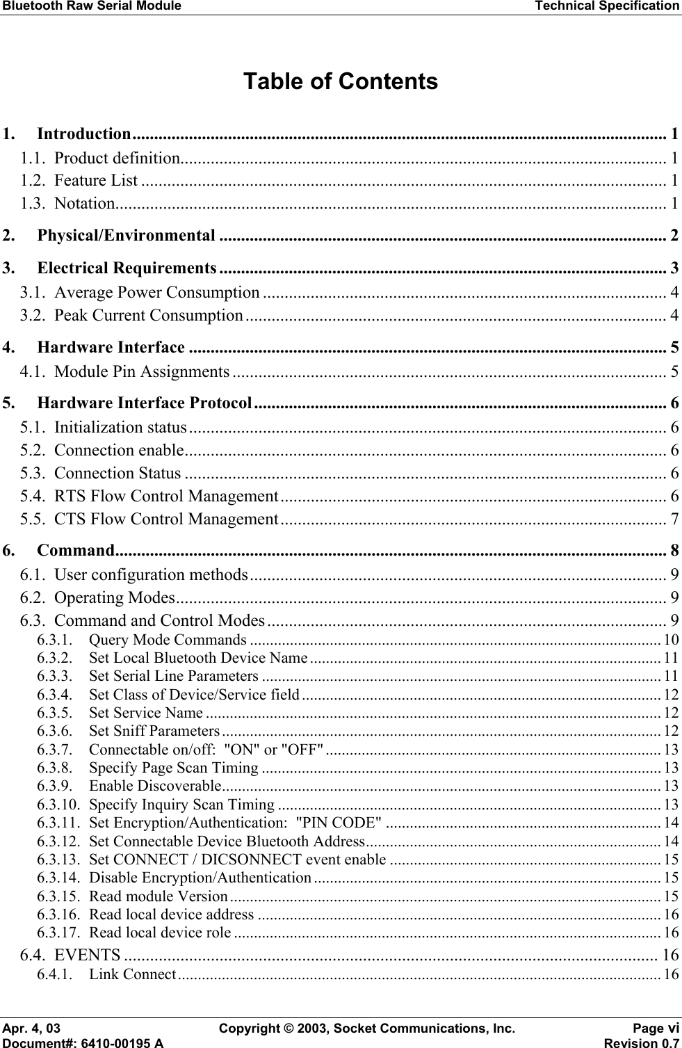
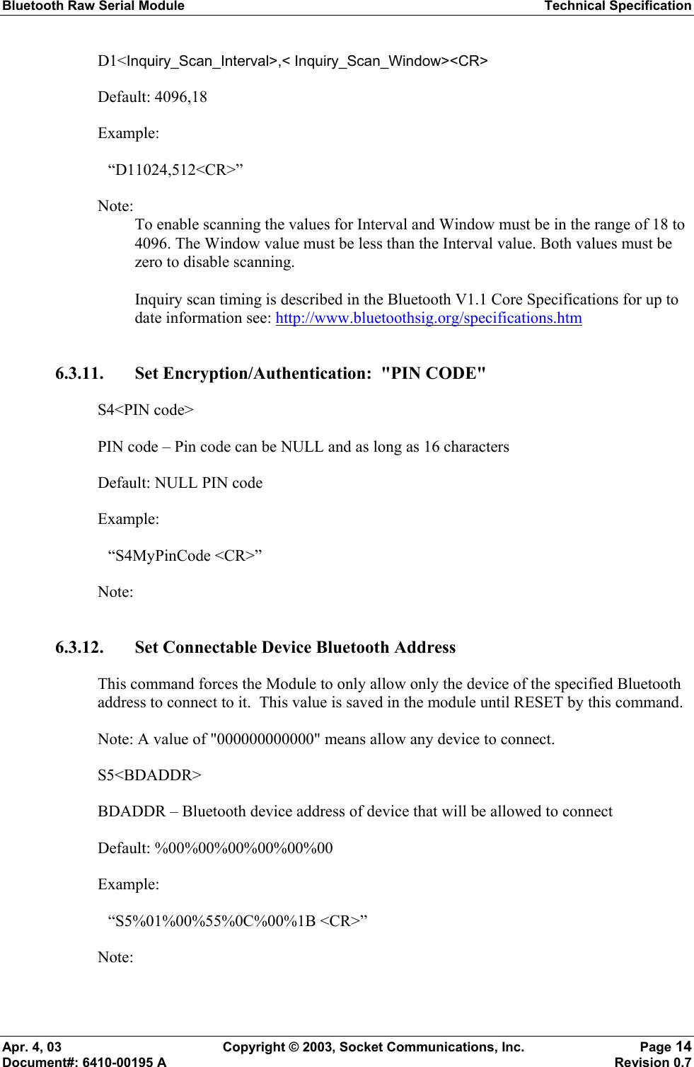
![Bluetooth Raw Serial Module Technical Specification Apr. 4, 03 Copyright © 2003, Socket Communications, Inc. Page 8 Document#: 6410-00195 A Revision 0.7 6. Command All printable characters can be entered directly via the keyboard. Any non-printable characters are entered in binary data format. Binary data format: Any non seven-bit ASCII data to be transmitted to the module will be encoded in the internet 'percent' notation. Any hex byte to be transmitted is preceded by the '%' sign and encoded in hex ASCII. Thus, to send the value 0xF5, the following bytes would be transmitted: "%F5". To send the '%' character is always transmitted as "%25". Thus, a Bluetooth address 'could' be transmitted as "%00%E0%03%45%F4%6D". Generic format: <command character><command type><command payload><CR> <command character> is one character from the set: [A-Z] <command type> is one character for the set: [0-9] <command payload> is variable in length. <CR> is the command terminator. The <command payload> is formed from printable ASCII characters from the code range 0x20 to 0x7E. Codes outside of this range are escaped using the percent (%) character followed by two hexadecimal digits. The percent character is always represented by the three characters: %25 The command terminator is character code 0x13 (carriage return), or character code 0x10 (line feed), or character codes 0x13, 0x10 (carriage return, line feed) An example command to set the friendly name to "Len's 100% serial module": F0Len's 100%25 serial module<CR> Character codes outside of the range of 0x20 to 0x7E are ignored. When using percent (%) to form hexadecimal character codes there must be exactly two hex digits using characters: [0-9, A-F, a-f]. Characters outside of this range cause the command to fail. Commands that fail return the four character sequence: NAK<CR> Commands that are accepted return the four character sequence: ACK<CR>](https://usermanual.wiki/Socket-Mobile/BTM-1/User-Guide-316477-Page-17.png)
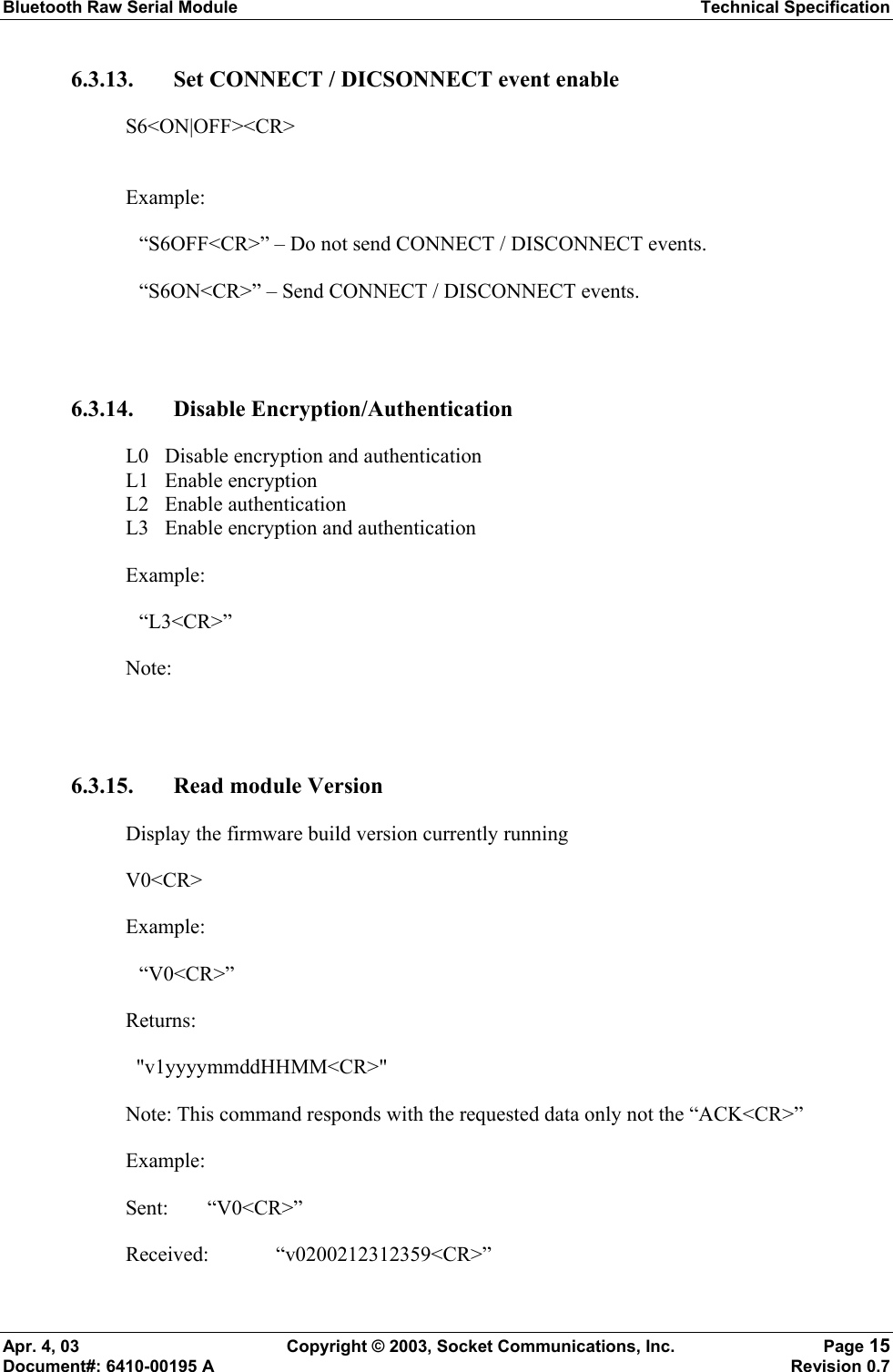
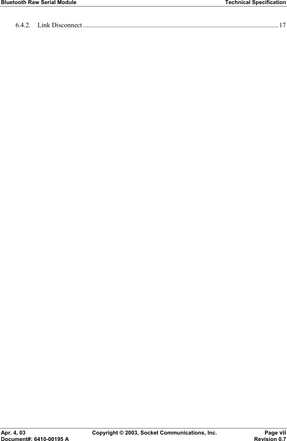
![Bluetooth Raw Serial Module Technical Specification Apr. 4, 03 Copyright © 2003, Socket Communications, Inc. Page 9 Document#: 6410-00195 A Revision 0.7 Commands that return payload data use the format: <command character><command type><command payload><CR> <command character> is one character from the set: [a-z] <command type> is one character for the set: [0-9] <command payload> is variable in length. <CR> is the command terminator. The command character is the "lower case" version of the local host command. 6.1. User configuration methods The user can interface with the Raw Serial Module in three distinct ways: · Dumb Terminal – debug environment or field updates · Windows GUI/Application – debug mode or field upgrade · Batch mode – manufacturing environment usage 6.2. Operating Modes The module interface has two modes: · BT Link Active state: In this case the Serial Interface looks like a raw serial port (TxD,RxD,CTS, etc. and GND). There is no intelligence in the BT module present from the Serial Interface perspective. This mode does not support the command and control modes described below. · BT Link Inactive state: this mode exists when a BT link is not existent: In this case the Serial Interface looks like a serial port that supports a number of command and control modes. Upon reset the unit comes up in “BT Link Inactive State”. After the first Bluetooth connection, the unit goes into “BT Link Active State”. It will stay in this state until the link is lost because the Master shuts it down, or there is an out-of-range condition. At this point it will return to the “BT Link Inactive State”. 6.3. Command and Control Modes Note that these commands are only available over the serial link, not over the air and are not available when the device is in the BT Link Active state.](https://usermanual.wiki/Socket-Mobile/BTM-1/User-Guide-316477-Page-18.png)