Socket Mobile BTM-4 KwikBlue4 Class 1 BC04 Bluetooth Module User Manual Revised Manual
Socket Mobile, Inc. KwikBlue4 Class 1 BC04 Bluetooth Module Revised Manual
Revised Manual

KwikBlue4-1
Bluetooth® Class 1 BC04 Module Manual
June 21, 2005 Copyright © 2004-2005 Socket Communications, Inc. Page 1
Document#: CONFIDENTIAL Revision 0.1
KwikBlue4-1
Bluetooth® Class 1 BC04 Module
Manual
8 Mbit Memory, UART - USB Interface
Bluetooth 2.0 + EDR
Socket P/N 8520-00096
Revision 0.1
June 21, 2005

Regulatory Approvals
FCC Statement
This equipment has been tested and found to comply with the limits for a Class B digital
device, pursuant to Part 15 of the FCC Rules. These limits are designed to provide reasonable
protection against harmful interference in a residential installation.
This equipment generates, uses and can radiate radio frequency energy and, if not installed and
used in accordance with the instructions, may cause harmful interference to radio communica-
tions. However, there is no guarantee that interference will not occur in a particular installation.
If this equipment does cause harmful interference to radio or television reception, which can be
determined by turning the equipment off and on, the user is encouraged to try to correct the
interference by one of the following measures:
Reorient or relocate the receiving antenna.
Increase the separation between the equipment and receiver.
Connect the equipment into an outlet on a circuit different from that to which the receiver
is connected.
Consult the dealer or an experienced radio/TV technician for help.
To assure continued compliance, any changes or modifications not expressly approved by the
party responsible for compliance could void the user's authority to operate this equipment.
(Example - use only shielded interface cables when connecting to computer or peripheral
devices).
FCC Radiation Exposure Statement
This equipment complies with FCC RF radiation exposure limits set forth for an uncontrolled
environment. This equipment should be installed and operated with a minimum distance of 20
centimeters between the radiator and your body.
This device complies with Part 15 of the FCC Rules. Operation is subject to the following two
conditions:
(1) This device may not cause harmful interference, and
(2) This device must accept any interference received, including interference that may cause
undesired operation.
This transmitter must not be co-located or operating in conjunction with any other antenna or
transmitter.
The antennas used for this transmitter must be installed to provide a separation distance of at
least 20 cm from all persons and must not be co-located or operating in conjunction with any
other antenna or transmitter.
CAUTION:
1) To comply with FCC RF exposure compliance requirements, a separation
distance of at least 20 cm must be maintained between the antenna of this
device and all persons.
2) This transmitter must not be co-located or operating in conjunction with
any other antenna or transmitter.

KwikBlue4-1
Bluetooth® Class 1 BC04 Module Manu al
June 21, 2005 Copyright © 2004-2005 Socket Communications, Inc. Page 2
Document#: CO NFIDENTIAL Revision 0.1
Reproduction of the contents of this manual without the permission of Socket Communications or
AboCom System is expressly prohibited.
Please be aware that the product described in this manual may change without notice.
This manual has been prepared with the greatest care regarding its contents. However, in the event that it
contains omissions, errors or any other misinformation, please feel free to direct comments to:
http://www.abocom.com.tw/or www.socketcom.com. for the details.
Other than the above, Socket Communications or AboCom System can assume no responsibility for
anything resulting from the application of information contained in this manual.
The OEM integrators of this module must keep the device and antenna 20cm away from all persons,
and the end user has no instructions to install this device.
If these conditions cannot be met then OEM integrators must seek their own approvals,
including their own FCC ID.
Caution

KwikBlue4-1
Bluetooth® Class 1 BC04 Module Manual
June 21, 2005 Copyright © 2004-2005 Socket Communications, Inc. Page 3
Document#: CONFIDENTIAL Revision 0.1
Copyright and Trademarks
The Bluetooth® word mark and logos are owned by the Bluetooth SIG, Inc. and any use of such marks by
Socket Communications is under license.
Socket Communications and are registered trademarks of Socket Communications, Inc.

KwikBlue4-1
Bluetooth® Class 1 BC04 Module Manual
June 21, 2005 Copyright © 2004-2005 Socket Communications, Inc. Page 4
Document#: CONFIDENTIAL Revision 0.1
Table of Contents
1. General.....................................................................................................................................................5
1.1 Purpose and Scope of Document ..................................................................................................... 5
1.2 Product Overview ............................................................................................................................ 5
2. Standard Operating Conditions ............................................................................................................5
3. Features List............................................................................................................................................5
3.1 Common Physical Layer Specifications............................................................................................. 6
3.2 Hardware Pin-assign........................................................................................................................... 7
3.3 RESET Sequence.............................................................................................................................. 10
3.4 UART (Universal Asynchronous Receiver Transmitter) ................................................................. 10
3.5 USB .................................................................................................................................................. 11
3.5.1 Summary of Supported Features ................................................................................................... 11
3.5.2 Description of Each Hardware Interface ....................................................................................... 11
3.5.3 RESET Control.............................................................................................................................. 11
3.5.4 Limitations..................................................................................................................................... 12
3.6 PCM.................................................................................................................................................. 13
3.6.1 Features.......................................................................................................................................... 13
3.6.2 Recommended Codec IC............................................................................................................... 13
4. Software Specifications.........................................................................................................................14
4.1 Software Architecture....................................................................................................................... 14
5. Application Note....................................................................................................................................15
5.1 Layout guideline............................................................................................................................... 15
5.2 Power source .................................................................................................................................... 15

KwikBlue4-1
Bluetooth® Class 1 BC04 Module Manual
June 21, 2005 Copyright © 2004-2005 Socket Communications, Inc. Page 5
Document#: CONFIDENTIAL Revision 0.1
1. General
1.1 Purpose and Scope of Document
This document describes a radio device incorporating Bluetooth® wireless technology known as a
Bluetooth Class 1 BC04 module. The Bluetooth module complies with the “Specification of the
Bluetooth System,” version 2.0 + EDR. This document describes the General design guideline for the
Bluetooth module.
1.2 Product Overview
The Bluetooth module contains CSR’s BC04-EXT chipset which has a complete transceiver radio and
baseband controller section: 16 bit RISC processor, RAM and Flash memory. Also built in are a high-
accuracy reference oscillator and a subclock for managing power to extremely low levels. Protocol
software is preloaded into the integrated Flash memory and interfaces to the HCI layer of the upper
layer protocol stack on an appropriate host system.
2. Standard Operating Conditions
Items Conditions
Operating Temperature -20° C to +85° C
Storage Temperature -40° C to +85° C
Supply Voltage; VCC 3.1 V to 3.6 V
Absolute Maximum Ratings
Supply Voltage VCC : -0.4 V ~ +3.6 V
3. Features List
Features Values
Power Level +16 dBm Max.
Program Memory 8 Mbits (512k x 16 bits) Flash
RAM 32k bytes x 16 bits
Reference Oscillator Built-in
Sub Clock Oscillator Built-in
Audio Interface PCM A-Law, µ-Law (CVSD)
Serial Data Interface UART (BCSP of H:4)
USB Interface USB 1.1 (OHCI and UHCI)
Physical Connection Board-to-board connection – solder down

KwikBlue4-1
Bluetooth® Class 1 BC04 Module Manual
June 21, 2005 Copyright © 2004-2005 Socket Communications, Inc. Page 6
Document#: CONFIDENTIAL Revision 0.1
3.1 Common Physical Layer Specifications
Operating Frequency 2400 MHz to 2483.5 MHz
Carrier Spacing 1.0 MHz
Channel 79
Duplexing TDD
Symbol Rate (Std data rate) 1 Mbps
Symbol Rate (EDR data rate) 2 & 3 Mbps
Modulation Method (Std data rate) GFSK BbT = 0.5
Modulation Method (EDR data rate) DQPSK & D8PSK
Reference Oscillator 16 MHz (built in)
RF input and output impedance Nominal 50 ohm
KwikBlue4-1
Bluetooth® Class 1 BC04 Module Manual
June 21, 2005 Copyright © 2004-2005 Socket Communications, Inc. Page 7
Document#: CONFIDENTIAL Revision 0.1
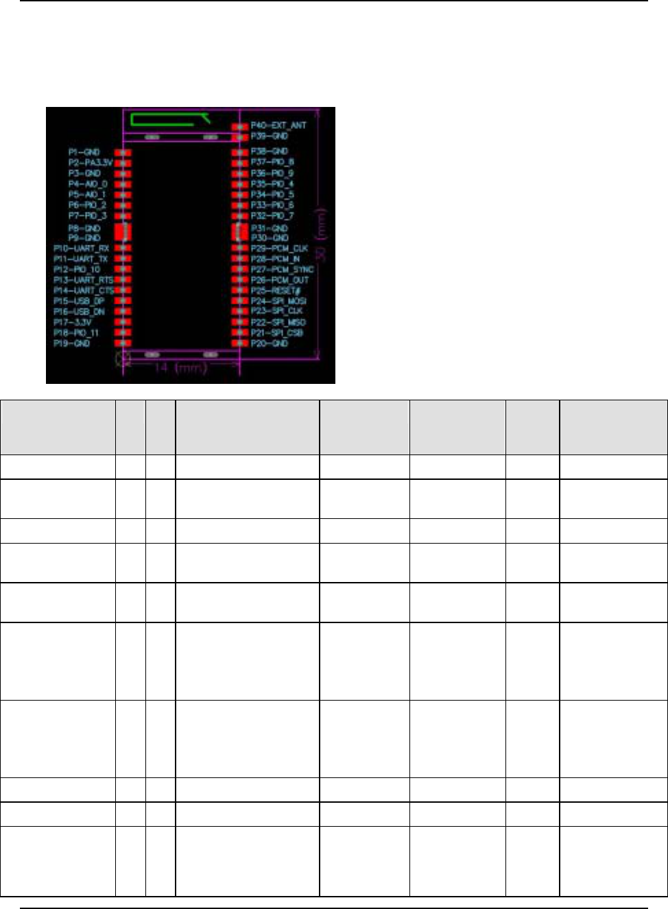
3.2 Hardware Pin-assign
Please reference the following pin-assignment for your application development.
Name No. I/O Description Pad Type Active State Usage T
y
pical External
Connection,
UART / PCM
GND 1 --- Ground VSS GND GROUND
VCC_PA 2 I Power for RF Power
Amplifier power = 3.3V
VCC POWER DC Power Source
GND_PA 3 --- Module PA ground VSS GND GROUND
AIO_0 4 I/O Programmable
input/output line
Bi-directional User
Defined
Programmable IO
AIO_1 5 I/O Programmable
input/output line
Bi-directional User
Defined
Programmable IO
PIO_2/
USB_PULL_UP
6 I/O PIO or USB pull-up (via
1.5kΩ resistor to
USB_D+)
Bi-directional
with
programmable
weak internal
pull-up/down
--- User
defined
Programmable IO
PIO_3/
USB_WAKE_UP
7 I/O PIO or output goes high
to wake up PC when in
USB mode or external
RAM chip select
Bi-directional
with
programmable
weak internal
pull-up/down
--- User
defined
Programmable IO
GND 8 --- Ground VSS GND GROUND
GND 9 --- Ground VSS GND GROUND
UART_RXD 10 I UART data input active
high
CMOS input
with weak
internal pull-
down
Hi:0
Lo:1
UART TxD

KwikBlue4-1
Bluetooth® Class 1 BC04 Module Manual
June 21, 2005 Copyright © 2004-2005 Socket Communications, Inc. Page 8
Document#: CONFIDENTIAL Revision 0.1
Name No. I/O Description Pad Type Active State Usage T
y
pical External
Connection,
UART / PCM
UART_TXD 11 O
UART data output active
high CMOS output Hi:0
Lo:1
UART RxD
UART_CTS 12 I UART clear to send
active low
CMOS input
with weak
internal pull-
down
Hi: De-assert
Lo: Assert
UART RTS
UART_RTS 13 O UART request to send
active low
CMOS output,
tristatable with
internal pull-up
Hi: De-assert
Lo: Assert
UART CTS
USB_DP 14 I/O USB data plus Bi-directional USB
USB_DN 15 I/O USB data minus Bi-directional USB
PIO_10 16 I/O Programmable
input/output line
Bi-directional
with
programmable
weak internal
pull-up/down
--- User
defined
Programmable IO
VCC 17 I Module main power 3.3V VCC VCC DC power source
PIO_11 18 I/O Programmable
input/output line
Bi-directional
with
programmable
weak internal
pull-up/down
--- User
defined
Programmable IO
GND 19 --- Ground VSS GND GROUND
GND 20 --- Ground VSS GND GROUND
SPI_CSB 21 I Chip select for
Synchronous Serial
Interface active low
CMOS input
with weak
internal pull-up
Hi: Power
Inactive
Lo: Power
Active
SPI Socket Only
SPI_MISO 22 O Serial Peripheral Interface
data output
CMOS output,
tristatable with
weak internal
pull- down
Hi: 1
Lo: 0
SPI Socket Only
SPI_CLK 23 I Serial Peripheral Interface
clock
CMOS input
with weak
internal pull-
down
Hi: Active
Lo: Inactive
SPI Socket Only
SPI_MOSI 24 I Serial Peripheral Interface
data input
CMOS input
with weak
internal pull-
down
Hi: 1
Lo: 0
SPI Socket Only
RESET# 25 I Reset if low CMOS input
with weak
internal
Hi: Active
(Reset)
Lo: Inactive
RESET# Host CPU port
PCM_OUT 26 O
Synchronous data output CMOS output,
tristatable with
internal weak
pull-down
Hi:1
Lo: 0
PCM PCM input

KwikBlue4-1
Bluetooth® Class 1 BC04 Module Manual
June 21, 2005 Copyright © 2004-2005 Socket Communications, Inc. Page 9
Document#: CONFIDENTIAL Revision 0.1
Name No. I/O Description Pad Type Active State Usage T
y
pical External
Connection,
UART / PCM
PCM_SYNC 27 I/O Synchronous data SYNC Bi-directional
with weak
internal pull-
down
Hi: Active
Lo: Inactive
PCM Frame Sync I/O
PCM_IN 28 I Synchronous data input CMOS input,
with internal
weak pull-
down
Hi:1
Lo: 0
PCM PCM output
PCM_CLK 29 I/O Synchronous data clock Bi-directional
with weak
internal pull-
down
Hi: 1
Lo: 0
PCM PCM Clock I/O
GND 30 --- Ground VSS GND GROUND
GND 31 --- Ground VSS GND GROUND
PIO_7/
RAM_CSB 32 I/O Programmable
input/output line
Bi-directional
with
programmable
weak internal
pull-up/down
--- User
defined
Programmable IO
PIO_6/
CLK_REQ 33 I/O PIO line or clock request
output to enable external
clock for external clock
line
Bi-directional
with
programmable
weak internal
pull-up/down
--- User
defined
Programmable IO
PIO_5/
USB_DETACH
34 I/O PIO line or chip detaches
from USB when this
input is high
Bi-directional
with
programmable
weak internal
pull-up/down
--- User
defined
Programmable IO
PIO_4/
USB_ON
35 I/O PIO or USB on (input
senses when VBUS is
high, wakes BlueCore2-
External)
Bi-directional
with
programmable
weak internal
pull-up/down
--- User
defined
Programmable IO
PIO_9 36 I/O Programmable
input/output line
Bi-directional
with weak
internal pull-
up/down
--- User
defined
Programmable IO
PIO_8 37 I/O Programmable
input/output line
Bi-directional
with weak
internal pull-
up/down
--- User
defined
Programmable IO
GND 38 --- Ground VSS GND GROUND
GND 39 --- Ground VSS GND GROUND
EXT_ANT 40 --- Optional antenna output Bi-directional
with DC block
RF
output
Optional antenna
output

KwikBlue4-1
Bluetooth® Class 1 BC04 Module Manual
June 21, 2005 Copyright © 2004-2005 Socket Communications, Inc. Page 10
Document#: CONFIDENTIAL Revision 0.1
3.3 RESET Sequence
RESET is asserted by module itself, the external reset circuit is not required.
3.4 UART (Universal Asynchronous Receiver Transmitter)
UART_TxD, UART_RxD, UART_RTS, UART_CTS form a conventional asynchronous data serial
port. The interface is designed to operate correctly when connected to other UART devices such as
the NS16550A. The signaling levels are 0V and VCC. The interface is programmable over a variety
of bit rates; none, even or odd parity; one or two stop bits and hardware flow control on or off. The
default condition on power-up is pre-assigned in the Flash memory.
The maximum UART data rate is 1.3824 Mbps. Two-way hardware flow control is implemented by
UART_RTS and UART_CTS. UART_RTS is an output and is active low. UART_CTS is an input
and is active low. These signals operate according to normal industry convention.

KwikBlue4-1
Bluetooth® Class 1 BC04 Module Manual
June 21, 2005 Copyright © 2004-2005 Socket Communications, Inc. Page 11
Document#: CONFIDENTIAL Revision 0.1
3.5 USB
USB interface is compliant with Universal Serial Bus Specification 1.1 and supports 12 Mbps “Full
Speed” and single ended data interface. And also, USB interface according to Bluetooth™
Specification 1.1 “USB transport layer” as well, including interface suggested by Intel for further
power management.
3.5.1 Summary of Supported Features
Items Description
Application The integrated BluetoothTM chip works as a “device” and answer on
“requests” from a “master host controller” as for example a PC.
Speed “High speed mode” only
USB Windows Class Wireless Controller (bDeviceClass=0xE0h)
USB Sub class RF Controller (bDeviceSubClass=0x01h)
USB Protocol code Bluetooth™ Programming (bDeviceProtocol=0x01)
OHCI/UHCI Supported
SCO support SCO supported as Isochronous transfer mode
(needed to be changed USB subclass to enable SCO over USB)
Transfer mode Bulk, Control and Isochronous supported
USB data packets
length All packet size supported according to Bluetooth™ Spec 2.0+EDR
Number of endpoints 6 end points
USB manufacture code Unless specified, persistent storage saving “Socket” as manufacturer
HCI extended
commands
All private commands will be capsulated to payload and de-capsulated
in Module Stack
3.5.2 Description of Each Hardware Interface
Module Pin Name I/O Requirement Description
USB_D+ D+ bi-dir Mandatory Defined in USB spec 1.1
USB_D- D- bi-dir Mandatory Defined in USB spec 1.1
3.5.3 RESET Control
Reset mode Requirement Description
Power On Reset Mandatory
Hardware reset. Power on reset circuit is built in Module
RESET port is not required to connecting Host for
production. To do HARD RESET, input high level (VIH) of
minimum 200 µs to reset terminal.
HCI reset
commands Mandatory Software reset. Supported by Socket Bluetooth™ Driver
Drive D+ D- low Mandatory USB defined reset

KwikBlue4-1
Bluetooth® Class 1 BC04 Module Manual
June 21, 2005 Copyright © 2004-2005 Socket Communications, Inc. Page 12
Document#: CONFIDENTIAL Revision 0.1
simultaneously
3.5.4 Limitations
1) Power Specific Limitations: today, the host controller of USB capable machines resides inside
a chip known as PIIX4. Because of the design, the USB host controller will not receive power
while the system is in S3 or S4. This means that a USB wakeup can only occur when the system
is in S1 or S2.
Another issue with the USB host controller is that, while a device is attached, it continually
snoops memory to see if there is any work that needs to be done. The frequency that it checks
memory is 1ms. This prevents the processor from dropping into a low power state known as C3.
Because the notebook processor is not able to enter the C3 state, SIGNIFICANT power loss will
occur. This is a real issue for business users – as a typical business user will spend almost 90% of
their time in the C3 state.
2) Other Limitations: data corruption may occur across isochronous endpoints. Endpoints one and
two may suffer from data corruption. USB provides 16-CRC on all data transfers. The USB has a
bit error rate of 10 –13 .
KwikBlue4-1
Bluetooth® Class 1 BC04 Module Manual
June 21, 2005 Copyright © 2004-2005 Socket Communications, Inc. Page 13
Document#: CONFIDENTIAL Revision 0.1
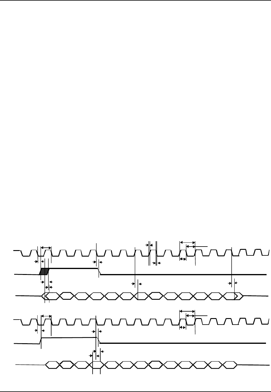
3.6 PCM
3.6.1 Features
The Bluetooth module implements an audio transcoder to translate between A-law, µ-law and
linear voice data from the host and A-l a w, µ-law and CVSD voice data over the air. Voice
interpolation for lost packets is also included. PCM_OUT, PCM_IN, PCM_CLK and
PCM_SYNC carry up to three bi-directional channels of voice data, each at 8 ks/s. The PCM
samples can be 8-bit A-law, 8-bit µ-law, 13-bit linear or 16-bit linear format. The PCM_CLK and
PCM_SYNC pins can be configured as inputs or outputs, depending on whether the Bluetooth
module is the master or slave of the PCM interface.
The PCM_SYNC operates at a fixed clock frequency of 8 KHz. When PCM_SYNC is operated
as an output (master mode) a clock frequency of 8 KHz is generated from this pin. When operated
as an input (slave mode) 8 KHz must be applied to this pin.
PCM_CLK operates at a fixed clock frequency of 256 KHz. When PCM_CLK is operated as an
output (master mode) a clock frequency of 256 KHz is generated from this pin. When operated as
an input (slave mode) 256 KHz must be input on this pin.
When used with the Motorola MC145483 PCM or compatible devices, bits 1 to 13 of the
PCM_OUT data carry the current output sample value. Bits 14 to 16 carry a three-bit signal level
value and these “level bits” vary the level of the audio signal output from the PCM device.
3.6.2 Recommended Codec IC
The Bluetooth module can be interfaced directly to the following PCM audio chips:
OKI MSM7705 four channel µ/A-law codec
Motorola MC145481 8-bit µ/A-law codec
Motorola MC145483SD 13-bit linear codec
Mitel MT93LI6 Echo canceling codec
Figure 1: PCM Bus Transfer Definition
Dtmsb
Dtmsb
17
6
5432 98 10
clksyn
PCM_CL
K
1211 13 14
D1 D2 D3 D4 D5 D6 D7 D8 D9 D10 D11 D12 D13
mc l
k
pw h
pw l
risel
fall
syncl
k
Dt13
Dtcl
k
PCM_SY N
C
PCM_OU
T
Hdsyn
Dval
17
6
5432 98 10
clksyn
PCM_CL
K
1211 13 14
D1 D2 D3 D4 D5 D6 D7 D8 D9 D10 D11 D12 D13
mc l
k
pw h
pw l
syncl
k
PCM_SY N
C
PCM_IN
Dinvl
Hdsyn
KwikBlue4-1
Bluetooth® Class 1 BC04 Module Manual
June 21, 2005 Copyright © 2004-2005 Socket Communications, Inc. Page 14
Document#: CONFIDENTIAL Revision 0.1
4. Software Specifications
The Bluetooth module contains the Bluetooth protocol stack (firmware) HCI (Host Controller Interface)
compliant with the “Specification of the Bluetooth System,” version 2.0+EDR.
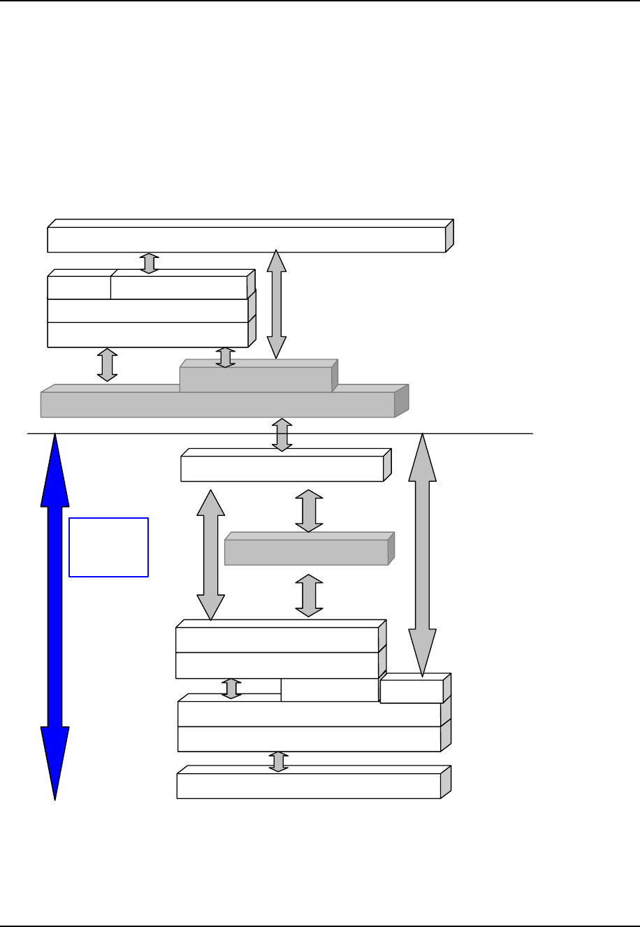
4.1 Software Architecture
The following figure shows typical implementation example of Bluetooth protocol stack using the
Bluetooth module. As shown in this figure, a Bluetooth protocol stack over HCI is required to
complete the full Bluetooth functionality.
Figure 2: Software Architecture
Bluetooth Radio
Radio Interface Driver
Base BandLink Controller
Link Manager
HCI Firmware
HCI MUX
UART(BCSP/H4)/USB physical driver
UART (BCSP/H4)/USB physical driver
Serial Stream MUX (BCSP)
HCI
L2CAP
SDP
RFCOMM
Software Application Interface
SOCKET
BLUETOOTH
MODULE
Serial Stream MUX (BCSP)
Voice

KwikBlue4-1
Bluetooth® Class 1 BC04 Module Manual
June 21, 2005 Copyright © 2004-2005 Socket Communications, Inc. Page 15
Document#: CONFIDENTIAL Revision 0.1
5. Application Note
5.1 Layout guideline
5.1.1 please follow the footprint of module.
5.1.2 Don’t put coppor foil or any trace under the antenna area.
5.1.3 Add a power de-coupling circuit for 3.3V and PA3.3V.
5.1.4 Suggest to take coppor foil or any trace away from the near side with our module.
5.1.5 Keep the USB trace shortly as possible.
5.2 Power source
5.2.1 Suggest to use a LDO regulator to convert your power into 3.3V for our module.