Socket Mobile BTM-4C KwikBlue4c Class 1 BC04 Bluetooth Module with 20-pin connector User Manual User s manual with product spec ADT Revise 0827
Socket Mobile, Inc. KwikBlue4c Class 1 BC04 Bluetooth Module with 20-pin connector User s manual with product spec ADT Revise 0827
Manual

BTM4KC
Manual
July 29, 2008 AboCom Page 1
Document#: CONFIDENTIAL Revision 0.1
BTM4KC
KwikBlue4c Class 1 BC04 Bluetooth Module
with 20-pin connector ( 8520-00145 )
Manual
8 Mbit Memory, UART Interface
Bluetooth 2.0 + EDR
Revision 0.1
July 29, 2008

BTM4KC
Manual
July 29, 2008 AboCom Page 2
Document#: CONFIDENTIAL Revision 0.1
Reproduction of the contents of this manual without the permission of AboCom System is expressly
prohibited.
Please be aware that the product described in this manual may change without notice.
This manual has been prepared with the greatest care regarding its contents. However, in the event that it
contains omissions, errors or any other misinformation, please feel free to direct comments to:
http://www.abocom.com.tw/
for the details.
Other than the above, AboCom System can assume no responsibility for anything resulting from the
application of information contained in this manual.

BTM4KC
Manual
July 29, 2008 AboCom Page 3
Document#: CONFIDENTIAL Revision 0.1
Copyright and Trademarks
The Bluetooth® word mark and logos are owned by the Bluetooth SIG, Inc. and any use of such marks by
Socket Communications is under license.

BTM4KC
Manual
July 29, 2008 AboCom Page 4
Document#: CONFIDENTIAL Revision 0.1
Table of Contents
1.1
Purpose and Scope of Document.................................................................................................5
1.2
Product Overview.......................................................................................................................5
2. Standard Operating Conditions........................................................................................................5
3. Features List......................................................................................................................................6
3.1 Common Physical Layer Specifications.........................................................................................6
3.2 Hardware Pin-assign......................................................................................................................7
3.3 RESET Sequence ..........................................................................................................................8
3.4 UART (Universal Asynchronous Receiver Transmitter) ................................................................8
3.5 RESET Control .............................................................................................................................8
3.6 PCM .............................................................................................................................................8
3.6.1 Features......................................................................................................................................8
3.6.2 Recommended Codec IC ............................................................................................................8
4. Software Specifications......................................................................................................................9
4.1 Software Architecture....................................................................................................................9
5. Application Note..............................................................................................................................10
5.1 Layout guideline..........................................................................................................................10
5.2 Power source...............................................................................................................................10
Appendix 1 Federal Communication Commission Interference Statement ......................................11
Appendix 2 Industry Canada Statement ............................................................................................12
BTM4KC
Manual
July 29, 2008 AboCom Page 5
Document#: CONFIDENTIAL Revision 0.1
1. General
1.1 Purpose and Scope of Document
This document describes a radio device incorporating Bluetooth® wireless technology known as a
Bluetooth Class 1 BC04 module. The Bluetooth module complies with the “Specification of the
Bluetooth System,” version 2.0 + EDR. This document describes the General design guideline for the
Bluetooth module.
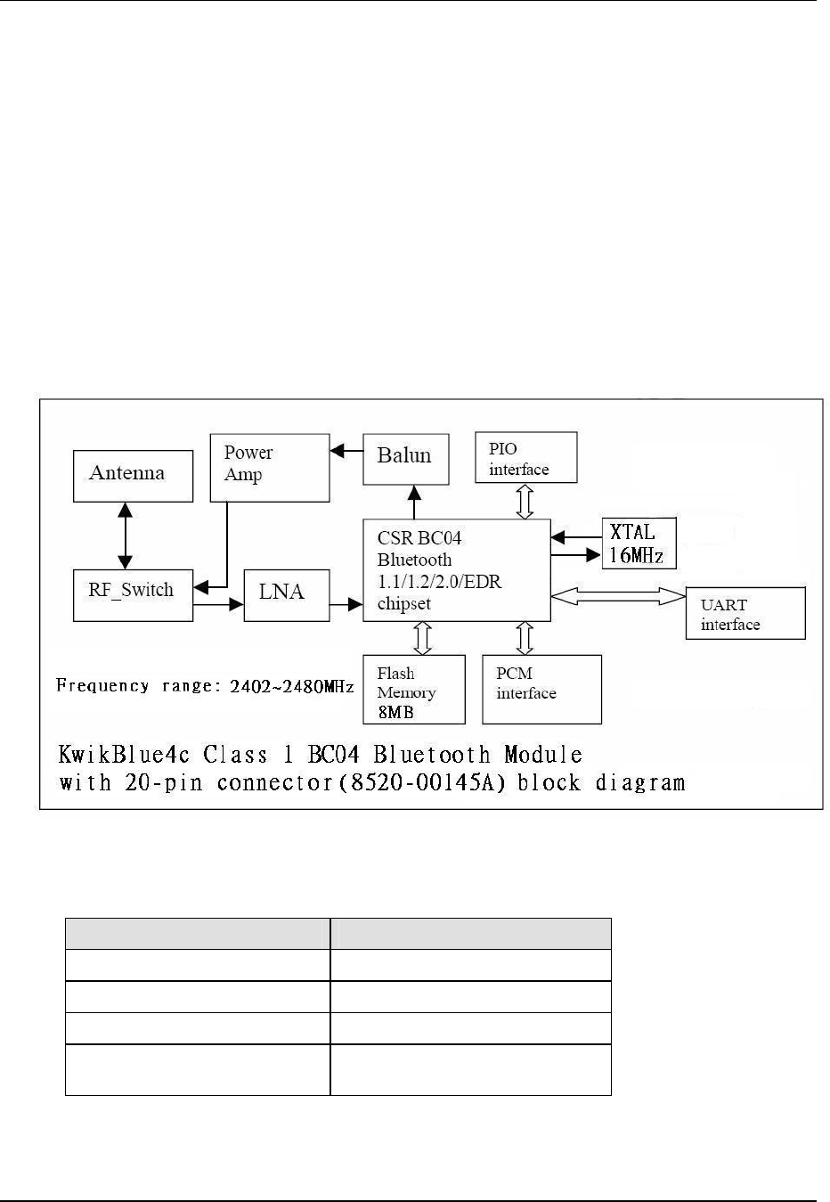
1.2 Product Overview
The Bluetooth module contains CSR’s BC04-EXT chipset which has a complete transceiver radio and
baseband controller section: 16 bit RISC processor, RAM and Flash memory. Also built in are a high-
accuracy reference oscillator and a subclock for managing power to extremely low levels. Protocol
software is preloaded into the integrated Flash memory and interfaces to the HCI layer of the upper
layer protocol stack on an appropriate host system. The functional block diagram has shown as below.
2. Standard Operating Conditions
Items Conditions
Operating Temperature -20° C to +85° C
Storage Temperature -40° C to +85° C
Supply Voltage; VCC 3.1 V to 3.6 V
Absolute Maximum Ratings
Supply Voltage VCC : -0.4 V ~ +3.6 V

BTM4KC
Manual
July 29, 2008 AboCom Page 6
Document#: CONFIDENTIAL Revision 0.1
3. Features List
Features Values
Power Level Basic Rate : +12 dBm Max.
EDR rate : -2 dBm Max.
Program Memory 8 Mbits (512k x 16 bits) Flash
RAM 32k bytes x 16 bits
Reference Oscillator Built-in
Sub Clock Oscillator Built-in
Audio Interface PCM A-Law, µ-Law (CVSD)
Serial Data Interface UART (BCSP of H:4)
Physical Dimension 14mm X 39mm
Physical Connection Board-to-board connector – 20PIN 10X2-0.5mm
(Panasonic AXK6F20347YG)
3.1 Common Physical Layer Specifications
Operating Frequency 2400 MHz to 2483.5 MHz
Carrier Spacing 1.0 MHz
Channel 79
Duplexing TDD
Symbol Rate (Std data rate) 1 Mbps
Symbol Rate (EDR data rate) 2 & 3 Mbps
Modulation Method (Std data rate) GFSK BbT = 0.5
Modulation Method (EDR data rate) DQPSK & D8PSK
Reference Oscillator 16 MHz (built in)
RF input and output impedance Nominal 50 ohm
BTM4KC
Manual
July 29, 2008 AboCom Page 7
Document#: CONFIDENTIAL Revision 0.1
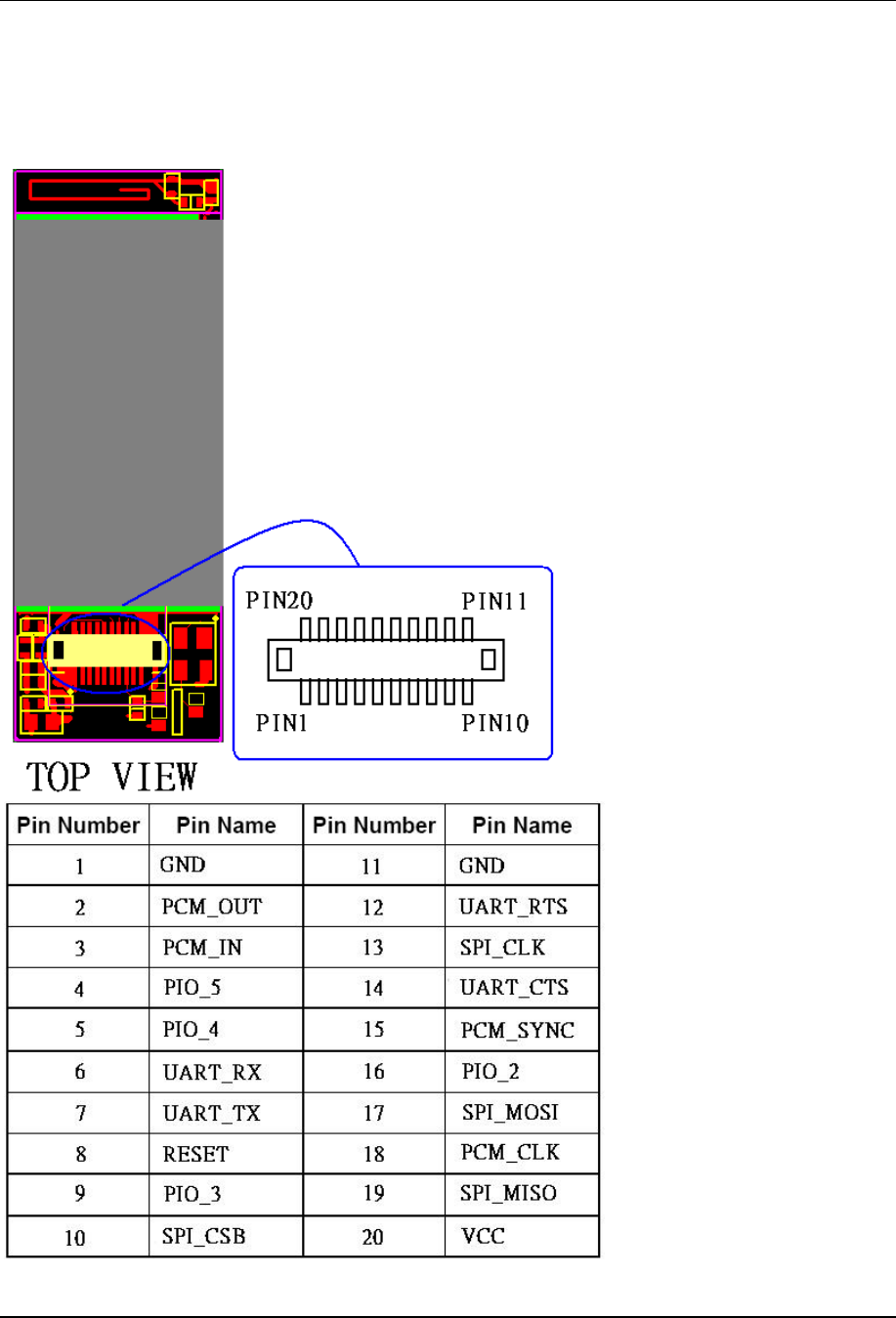
3.2 Hardware Pin-assign
Please reference the following pin-assignment for your application development.

BTM4KC
Manual
July 29, 2008 AboCom Page 8
Document#: CONFIDENTIAL Revision 0.1
3.3 RESET Sequence
RESET is asserted by module itself, the external reset circuit is not required.
3.4 UART (Universal Asynchronous Receiver Transmitter)
UART_TX, UART_RX, UART_RTS, UART_CTS form a conventional asynchronous data serial
port. The interface is designed to operate correctly when connected to other UART devices such as
the NS16550A. The signaling levels are 0V and VCC. The interface is programmable over a variety
of bit rates; none, even or odd parity; one or two stop bits and hardware flow control on or off. The
default condition on power-up is pre-assigned in the Flash memory.
The maximum UART data rate is 1.3824 Mbps. Two-way hardware flow control is implemented by
UART_RTS and UART_CTS. UART_RTS is an output and is active low. UART_CTS is an input
and is active low. These signals operate according to normal industry convention.
3.5 RESET Control
Reset mode Requirement
Description
Power On Reset Mandatory Hardware reset. Power on reset circuit is built in Module
RESET port is not required to connecting Host for
production.
HCI reset
commands Mandatory Software reset. Supported by AboCom Bluetooth™ Driver
3.6 PCM
3.6.1 Features
The Bluetooth module implements an audio transcoder to translate between A-law, µ-law and
linear voice data from the host and A-l a w, µ-law and CVSD voice data over the air. Voice
interpolation for lost packets is also included. PCM_OUT, PCM_IN, PCM_CLK and
PCM_SYNC carry up to three bi-directional channels of voice data, each at 8 ks/s. The PCM
samples can be 8-bit A-law, 8-bit µ-law, 13-bit linear or 16-bit linear format. The PCM_CLK and
PCM_SYNC pins can be configured as inputs or outputs, depending on whether the Bluetooth
module is the master or slave of the PCM interface.
3.6.2 Recommended Codec IC
The Bluetooth module can be interfaced directly to the following PCM audio chips:
OKI MSM7705 four channel µ/A-law codec
Motorola MC145481 8-bit µ/A-law codec
Motorola MC145483SD 13-bit linear codec
Mitel MT93LI6 Echo canceling codec
BTM4KC
Manual
July 29, 2008 AboCom Page 9
Document#: CONFIDENTIAL Revision 0.1
4. Software Specifications
The Bluetooth module contains the Bluetooth protocol stack (firmware) HCI (Host Controller Interface)
compliant with the “Specification of the Bluetooth System,” version 2.0+EDR.
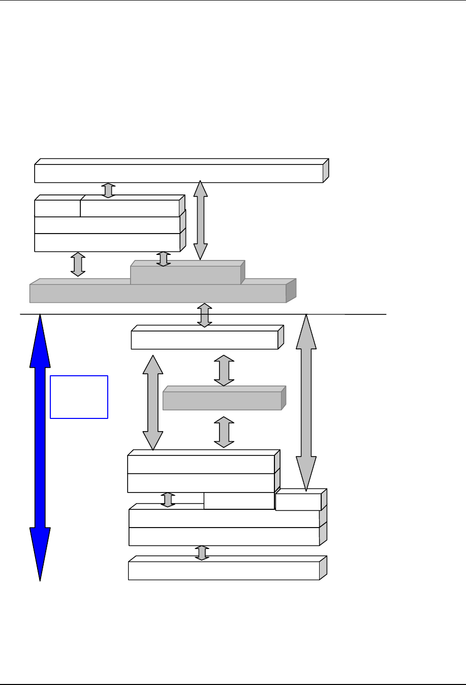
4.1 Software Architecture
The following figure shows typical implementation example of Bluetooth protocol stack using the
Bluetooth module. As shown in this figure, a Bluetooth protocol stack over HCI is required to
complete the full Bluetooth functionality.
Figure 1: Software Architecture
Bluetooth Radio
Radio Interface Driver
Base BandLink Controller
Link Manager
HCI Firmware
HCI MUX
UART(BCSP/H4)/USB physical driver
UART (BCSP/H4)/USB physical
driver
Serial Stream MUX (BCSP)
HCI
L2CAP
SDP
RFCOMM
Software Application Interface
BTM4KC
BLUETOOTH
MODULE
Serial Stream MUX (BCSP)
Voice

BTM4KC
Manual
July 29, 2008 AboCom Page 10
Document#: CONFIDENTIAL Revision 0.1
5. Application Note
5.1 Layout guideline
5.1.1 please follow the footprint of module.
5.1.2 Don’t put coppor foil or any trace under the antenna area.
5.1.3 Add a power de-coupling circuit for 3.3V and PA3.3V.
5.1.4 Suggest to take coppor foil or any trace away from the near side with our module.
5.2 Power source
5.2.1 Suggest to use a LDO regulator to convert your power into 3.3V for our module.

BTM4KC
Manual
July 29, 2008 AboCom Page 11
Document#: CONFIDENTIAL Revision 0.1
Appendix 1 Federal Communication Commission Interference Statement
This equipment has been tested and found to comply with the limits for a Class B digital
device, pursuant to Part 15 of the FCC Rules. These limits are designed to provide
reasonable protection against harmful interference in a residential installation. This
equipment generates, uses and can radiate radio frequency energy and, if not installed
and used in accordance with the instructions, may cause harmful interference to radio
communications. However, there is no guarantee that interference will not occur in a
particular installation. If this equipment does cause harmful interference to radio or
television reception, which can be determined by turning the equipment off and on, the
user is encouraged to try to correct the interference by one of the following measures:
- Reorient or relocate the receiving antenna.
- Increase the separation between the equipment and receiver.
- Connect the equipment into an outlet on a circuit different from that
to which the receiver is connected.
- Consult the dealer or an experienced radio/TV technician for help.
FCC Caution: Any changes or modifications not expressly approved by the party
responsible for compliance could void the user's authority to operate this equipment.
This device complies with Part 15 of the FCC Rules. Operation is subject to the
following two conditions: (1) This device may not cause harmful interference, and (2)
this device must accept any interference received, including interference that may
cause undesired operation.
This equipment complies with FCC RF radiation exposure limits set forth for an
uncontrolled environment. To maintain compliance with FCC RF exposure compliance
requirements, please avoid direct contact to the transmitting antenna during transmitting
.
This device is intended only for OEM integrators under the following conditions:
The transmitter module may not be co-located with any other transmitter or antenna,
As long as the condition above is met, further transmitter test will not be required.
However, the OEM integrator is still responsible for testing their end-product for any
additional compliance requirements required with this module installed (for example,
digital device emissions, PC peripheral requirements, etc.).
IMPORTANT NOTE:
In the event that the condition can not be met (for example certain laptop configurations
or co-location with another transmitter), then the FCC authorization is no longer
considered valid and the FCC ID can not be used on the final product. In these
circumstances, the OEM integrator will be responsible for re-evaluating the end product
(including the transmitter) and obtaining a separate FCC authorization.
End Product Labeling
The final end product must be labeled in a visible area with the following: “Contains
FCC ID: LUBBTM-4C.

BTM4KC
Manual
July 29, 2008 AboCom Page 12
Document#: CONFIDENTIAL Revision 0.1
Manual Information To the End User
The OEM integrator has to be aware not to provide information to the end user
regarding how to install or remove this RF module in the user’s manual of the end
product which integrates this module.
The end user manual shall include all required regulatory information/warning as show
in this manual.
Appendix 2 Industry Canada Statement
This device complies with RSS-210 of the Industry Canada Rules. Operation is subject
to the following two conditions:
1) this device may not cause interference and
2) this device must accept any interference, including interference that may cause
undesired operation of the device