Socket Mobile CF6V2 NFC Reader-Scan Card User Manual Socket Mobile CF RFID Reader Card User s Guide
Socket Mobile, Inc. NFC Reader-Scan Card Socket Mobile CF RFID Reader Card User s Guide
Users Manual
SoMo 655 RFID w/ NFC Reader Card™
SoMo 655 RFID w/ NFC Reader-Scan Card™
Series 6
User’s Guide

4/2014 Document # 6410-00266 N
Copyright Notice
Copyright © 2014 Socket Mobile, Inc. All rights reserved.
Socket, the Socket logo and Mobility Friendly are registered trademarks of Socket
Mobile, Inc. SOMO 655 RFID Reader Card, SOMO 655 RFID Reader-Scan Card, SoMo,
RFID Demo, SocketScan Plug-in, and SocketScan Trigger are registered trademarks or
trademarks of Socket Mobile, Inc. All other brand and product names are
trademarks of their respective holders.
The SOMO 655 RFID Reader Card and SOMO 655 RFID Reader-Scan Card contains
technology licensed under United States Patent No. 5,902,991 and 7,003,627.
Reproduction of the contents of this manual without the permission of Socket
Mobile is expressly prohibited. Please be aware that the products described in this
manual may change without notice.
Feel free to contact Socket Mobile at:
Socket Mobile, Inc.
39700 Eureka Drive
Newark, CA 94560-4808
USA
Other than the above, Socket Mobile can assume no responsibility for anything
resulting from the application of information contained in this manual.
Please refrain from any applications of the SOMO 655 RFID Reader Card or SOMO
655 RFID Reader-Scan Card that are not described in this manual. Please refrain from
disassembling the device. Disassembly of this device will void the product warranty.
You can track new product releases, software updates and technical bulletins by
visiting the Socket Mobile website at: http://www.socketmobile.com/
Table of Contents
COPYRIGHT NOTICE 2
1 | INTRODUCTION 5
About the Software 6
Package Contents 6
System Compatibility Requirements 6
Accessory 7
Product Registration 7
2 | SETUP FOR THE SOMO® 8
STEP 1: Assign Trigger Button(s) 9
STEP 2: Start SocketScan Plug-in 13
STEP 3: Insert the Card 13
STEP 4: Open Your Application 14
STEP 5: Read Data into Your Application 15
3 | SOCKETSCAN PLUG-IN SOFTWARE 18
RFID Settings 19
Symbology Selector 22
SocketScan Trigger 23
DUAL DEVICE SUPPORT 25
4 | RFID DEMO 26
Read an RFID Tag 27
Enable Inventory and Loop Modes 29
Select Tag Type 30
ADVANCED: Write to Tag 31
APPENDICES
A PRODUCT SPECIFICATIONS 34
B HF RFID STANDARDS AND TAG DESCRIPTIONS36
ISO15693 36
Tag-it HF 40
I·Code1 41
PicoTag 42
ISO14443 43
C BARCODE LABEL SPECIFICATIONS 46
D ENABLING OR DISABLING SYMBOLOGIES 47
E LASER DECODE ZONE 49
F TROUBLESHOOTING 50
1 | Introduction
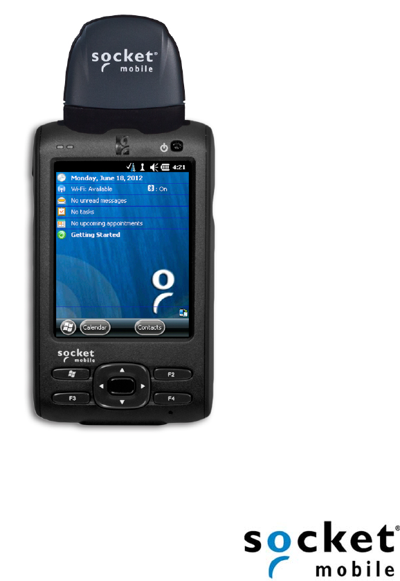
The Socket Mobile SoMo 655 RFID Reader Card Series 6 enables you to can add high
frequency RFID read/write capability to your Socket SoMo® handheld computer or
other Windows Mobile based device.
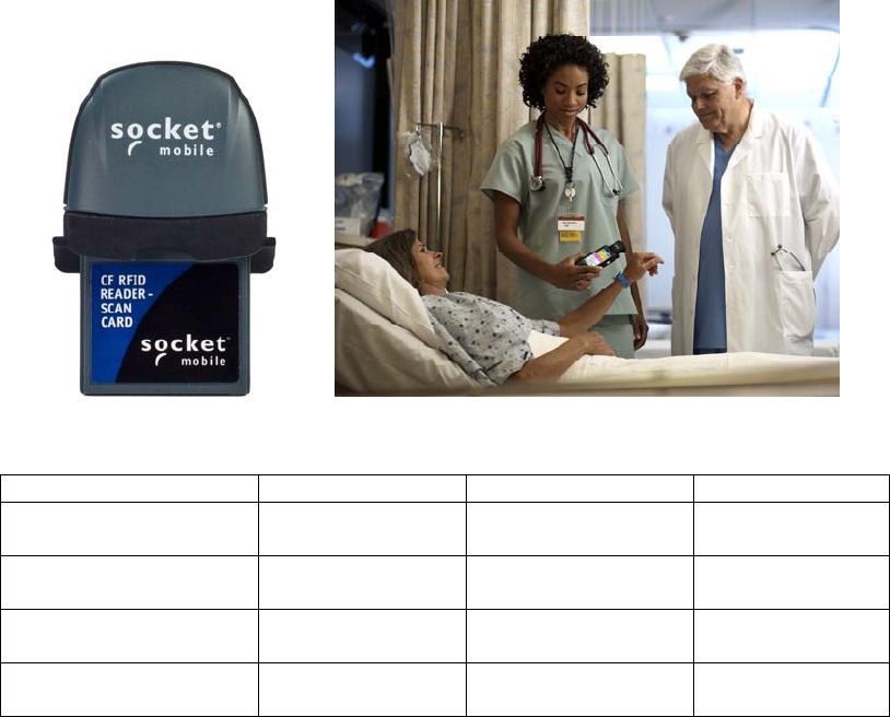
For applications that require both RFID and barcode reading functionality, the series
includes the dual-function SOMO 655 RFID Reader-Scan Card 6P2, which offers both
capabilities in the same compact form factor.
All three versions read and write to all ISO 15693 and many proprietary 13.56 MHz
RFID tags.
The SoMo 655 RFID Reader Card Series 6 includes three versions:
Model SKU# RFID Reader/Writer Barcode Scanner
SoMo 655 RFID w/ NFC
Reader 6E2
RF5407-1548 Yes Not included
SoMo 655 RFID w/ NFC
Reader 6P2
RF5408-1549 Yes Class 2 laser (2D)
SoMo 655Rx RFID w/
NFC Reader 6E2Rx
RF5409-1572 Yes Not included
SoMo 655Rx RFID w/
NFC Reader 6P2Rx
RF5410-1573 Yes Class 2 laser (2D)
The SOMO 655 RFID Reader Cards feature a sleek design with no cables or batteries.
The Battery Friendly® product draws minimal power from the host device, allowing
long-lasting operation.
CHAPTER 1: INTRODUCTION 5
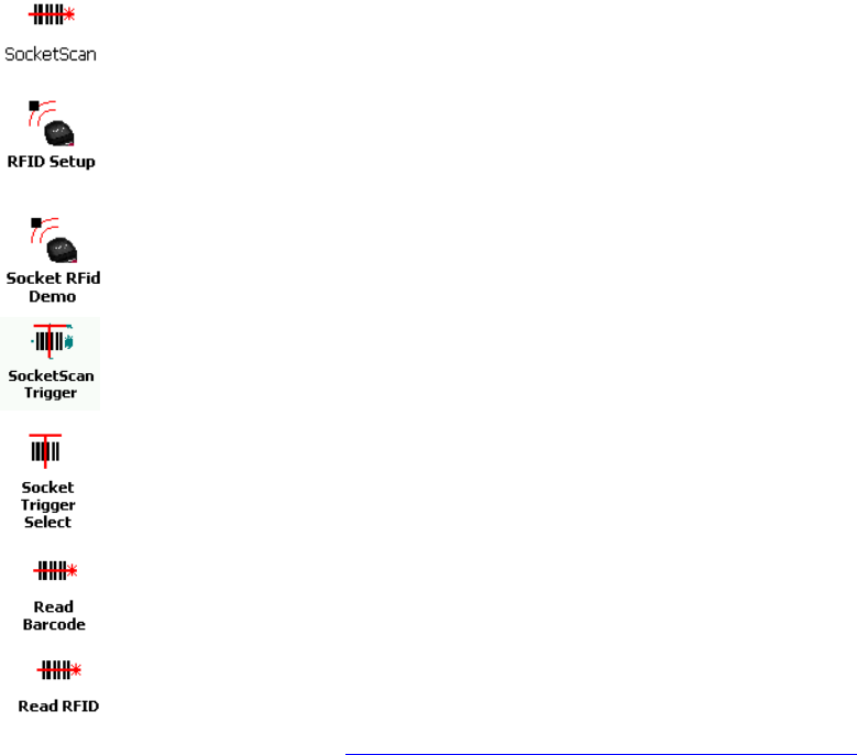
About the Software
SocketScan Plug-in ™ software enters the RFID tag ID or barcode data
directly into any open Windows program, as if the data were manually
typed. Includes configuration utility.
The RFID Setup utility allows you configure what kinds of data are
returned after reading RFID tags, including tag ID, tag memory, tag types,
tag type prefix, etc.
Socket Mobile RFID Demo allows you to read memory blocks of selected
RFID tags in range in either Inventory Mode or a continuous Loop
Mode. Advanced users can write data to the RFID memory.
SocketScan Trigger places a software trigger on your screen that you
can tap to trigger the RFID reader or barcode scanner. Installation is
optional.
The Socket Mobile Trigger Select program allows you to press a button
to quickly switch between the RFID and laser scanning modes of the
SOMO 655 RFID Reader-Scan Card.
The Read Barcode program allows you to assign a button on your
device to triggering the barcode laser scanner.
The Read RFID program allows you to assign a button on your device to
trigger the RFID reader.
For software updates, please visit: http://www.socketmobile.com/support/downloads
Package Contents
SoMo 655 RFID Reader Card
SocketScan Plug-in Installation (download)
Booklet with copyright and warranty information
System Compatibility Requirements
Any of the following Windows Mobile versions:
Windows Embedded Handheld
Windows Mobile 2003, 2003SE or 5.0 for Pocket PC
Windows Mobile 6 Classic/Professional
Available CompactFlash slot
Software installation requires a host PC with Microsoft ActiveSync or Windows
Mobile Device Center software
6

CHAPTER 1: INTRODUCTION 7
Accessory
DuraCase is a protective silicone cover for the SoMo handheld computer and RFID card.
http://www.socketmobile.com/products/handheld-computer/accessories/flexguard-SoMo 655-
card/
Product Registration
Socket Mobile highly recommends that all customers register their products. Registered
users receive priority technical support and can opt to receive product updates, and special
offers. Register online at: http://support.socketmobile.com/
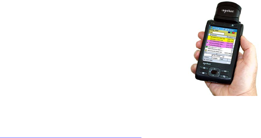
2 | Setup for the SoMo®
This chapter shows how to install, configure, and use the SOMO 655
RFID Reader Card Series 6 on any version of the Socket Mobile SoMo
handheld computer.
Setup Summary
STEP 1: Assign a trigger button.
STEP 2: Start SocketScan Plug-in.
STEP 3: Insert the card.
STEP 4: Read tag IDs into your program.
Note: No software installation is required to use the SOMO 655 RFID Reader Card on
the SoMo. However, you may choose to upgrade the SocketScan Plug-in software.
The latest software is available online at:
http://www.socketmobile.com/support/downloads
8
STEP 1: Assign Trigger Button(s)
You must set up a mechanism for triggering the SOMO 655 RFID Reader Card.
Hardware button(s) are the best triggering method from a handheld device.
Note: If you do not want to assign a hardware button, you use SocketScan Trigger
software, which enables you to tap on a software icon to trigger SocketScan Plug-in
and the RFID reader/barcode scanner.
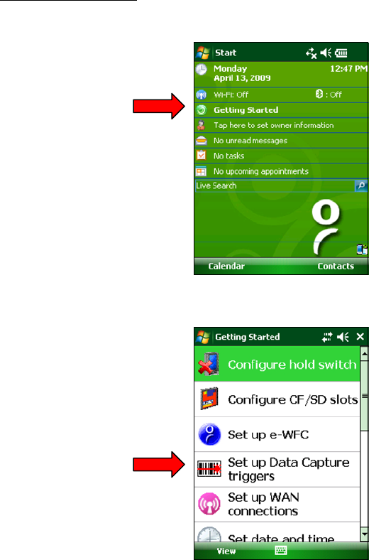
Windows Mobile 6
1. In the Today screen, tap Getting Started.
2. In the list, tap on Set up Data Capture triggers.
CHAPTER 2: SETUP FOR THE SOMO 9
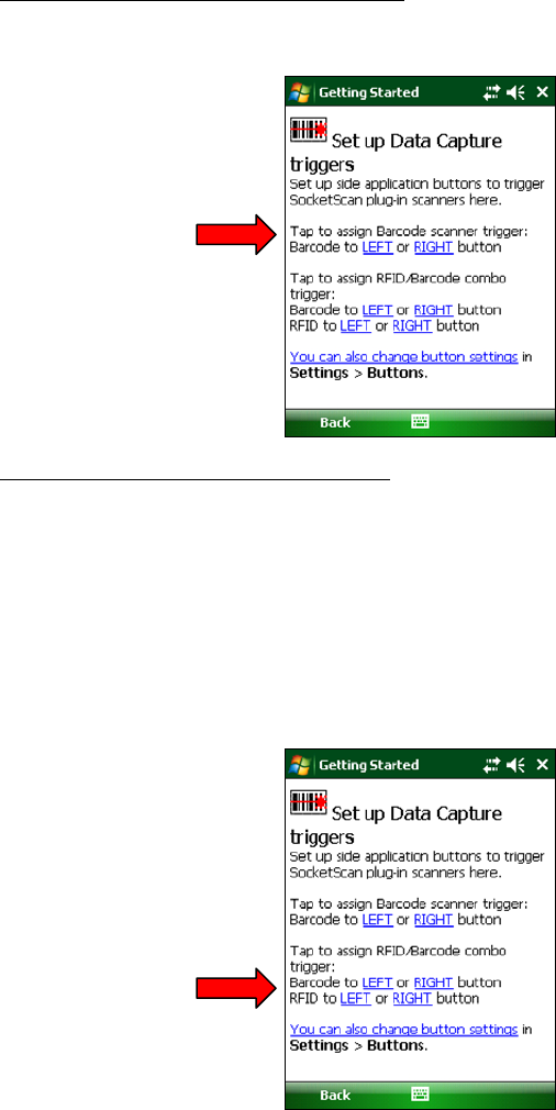
3. SOMO 655 RFID Reader Card 6E2/6E2Rx:
Tap LEFT or RIGHT in the first set of links. The SoMo will automatically set up the
trigger button and send a confirmation message to your inbox.
SOMO 655 RFID Reader-Scan Card 6P2
In the second set of links, tap LEFT or RIGHT for your barcode scanner trigger.
The SoMo will automatically set up the trigger button and send a confirmation
message to your inbox.
You will return to the list of Getting Started tutorials. Tap Set up Data
Capture triggers.
For the RFID reader trigger, tap on the link for the side you did not choose for
the barcode scanner trigger. The SoMo will automatically set up the trigger
button and send a confirmation message to your inbox.
10
Windows Mobile 5
Please refer to the chart below to determine which SocketScan Plug-in functions you
would like to assign to buttons on your device.
Note: If you have the SOMO 655 RFID Reader-Scan Card 6P2, SocketScan Plug-in allows
you to configure up to four buttons for launching SocketScan Plug-in and/or
triggering the RFID reader or barcode scanner.
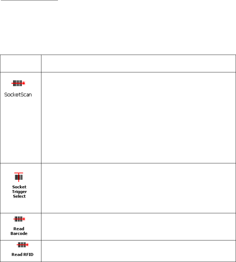
Program What happens when you press a button assigned to this
program?
If SocketScan Plug-in is not open, SocketScan Plug-in will launch.
If SocketScan Plug-in is open and you have the SOMO 655 RFID Reader Card
6E2/6E2Rx, the RFID reader will activate.
If SocketScan Plug-in is open and you have the SOMO 655 RFID Reader-Scan
Card 6P2, either the RFID reader or the laser scanner will activate,
depending on which mode the card is in.
If you assign only one hardware button for use with the SOMO 655
RFID Reader Card, this is the program that should be assigned.
If you do not assign a button to SocketScan Plug-in, you can only start
SocketScan Plug-in by manually tapping through menus.
If you are using the SOMO 655 RFID Reader-Scan Card 6P2, this program
will switch the device from RFID mode to barcode scanning mode, or vice
versa. This is designed to be used with a trigger button assigned to
SocketScan Plug-in. You can also use Socket Trigger Select to toggle to
other Socket Mobile barcode scanners that use a software trigger.
The laser bar ode scanner will activate. SocketScan Plug-in must be running.
The RFID reader will activate. SocketScan Plug-in must be running.
CHAPTER 2: SETUP FOR THE SOMO 11
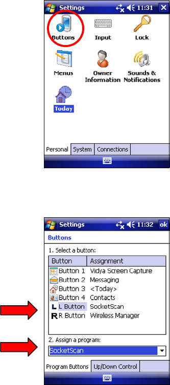
1. Tap Start | Settings | Buttons.
2. In the Button list, select a button. In the drop-down menu, select the program. If
desired, repeat to assign additional trigger buttons. When done, tap ok.
Note: For best ergonomics, choose the left or right buttons.
12
STEP 2: Start SocketScan Plug-in
1. If you assigned a hardware button to SocketScan Plug-in, you can
press the button to quickly launch the program. Otherwise, tap Start
| Programs | SocketScan Plug-in folder | SocketScan Plug-in.
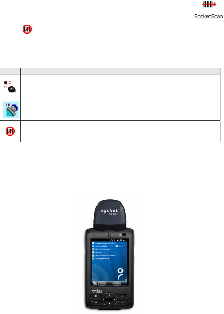
2. An icon will appear in the task tray of the Today screen indicating that the
system does not detect the RFID reader.
When SocketScan Plug-in is running, any of the following icons will appear in the
task tray of the Today screen:
Icon Meaning.
Card detected, RFID mode. SocketScan Plug-in detects the card and is ready
to read RFID tags.
Card detected, scanning mode. SocketScan Plug-in detects the card and is
ready to read barcodes.
No RFID Reader Card detected. The reader card is either missing or
improperly inserted.
STEP 3: Insert the Card
1. Open the card slot cover on top of the SoMo.
2. Insert the card into the CompactFlash slot. Make sure the card is right-side up,
with the blue label on top. Push the card all the way into the slot.
CHAPTER 2: SETUP FOR THE SOMO 13
Windows Mobile 5: If you have the SOMO 655 RFID Reader-Scan Card 6P2, and you
did not assign buttons to Trigger ISC or Trigger RFID, make sure the card is in the
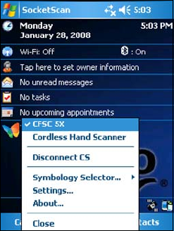
correct mode you wish to use. The SocketScan Plug-in icon at the bottom of the
Today screen indicates your current mode.
To switch modes, do either of the following:
If you assigned a button to Trigger Select, press the button.
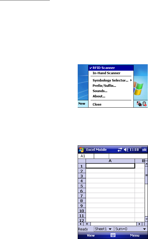
Tap on the SocketScan Plug-in icon. In the pop-up menu, tap to select the
card mode you want.
STEP 4: Open Your Application
Open the application that you want to receive the data (e.g., Excel, Notepad, etc.).
Place the cursor where you want to enter data.
Note: If reading RFID tags into Excel, you may want to widen the cells to fit the
full tag ID, which may exceed 20 characters.
14
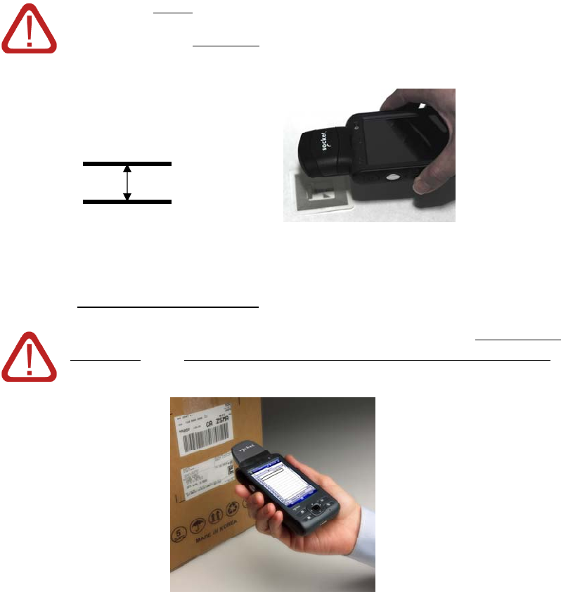
STEP 5: Read Data into Your Application
Please note that the correct positions for RFID reading and barcode
scanning are very different!
CORRECT RFID POSITION:
Hold the card parallel to and directly above the tag, at most
3.0 inches above the tag.
Parallel,
3.0 inches (7.6 cm)
maximum
Note: The LED will turn amber to indicate that the card is reading tag IDs.
CORRECT BARCODE SCANNING POSITION:
CHAPTER 2: SETUP FOR THE SOMO 15
Hold the card so that the lens is angled about 45° to the
barcode and at least 2.0 inches away from the barcode. The
red laser line should cover the entire width of the barcode.
Note: The proper scanning distance and angle vary depending on the size, type,
quality, and print surface of the barcode.
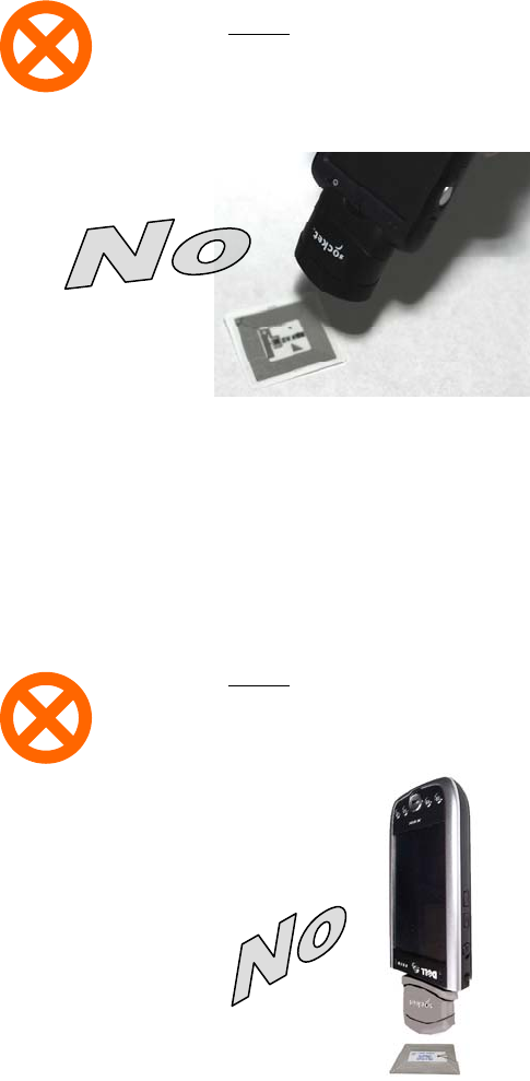
WRONG RFID POSITION:
DO NOT direct the RFID Reader-Scan Card at an angle
towards the tag.
WRONG RFID POSITION:
DO NOT hold the RFID Reader-ScanCard perpendicular to
the tag.
16
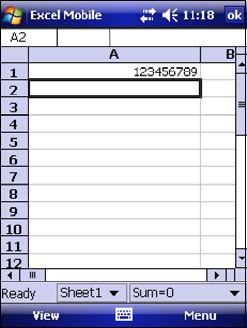
When data is read, a beep should sound indicating a good read, and data should
appear in your application.
For example, in an Excel Mobile spreadsheet, data should appear in the cell you
highlighted. The next cell should now be highlighted, ready for the next scan/read.
If the card fails to read data within a few seconds, you must try again.
Note: By default, the RFID reader will return the tag ID. The RFID Setup utility can
be used so that the RFID Reader-Scan Card returns only the tag data, or the tag
ID plus the tag data. (See the next page for instructions.)
CHAPTER 2: SETUP FOR THE SOMO 17
3 | SocketScan Plug-in Software
This chapter shows how to install, configure, and use the
SOMO 655 RFID Reader Card Series 6 on a Windows Mobile
powered device.
Application Features
RFID settings
Symbology selector
SocketScan Trigger.
Version information.
18
RFID Settings
Note: These settings are only used with the SocketScan Plug-in keyboard wedge
programs and Scan Demo.
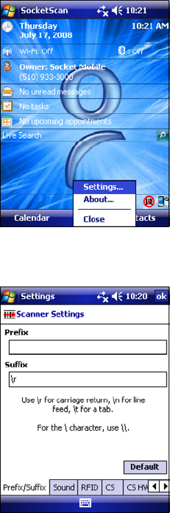
1. Tap on the SocketScan Plug-in icon. In the pop-up menu, tap Settings.
2. In the Prefix/Suffix screen, enter the characters you would like added to
each read/scan of data (128 character maximum).
Note: Only
printable ASCII
characters can be
used as prefixes or
suffixes.
Note:
The default suffix is a carriage return.
If in the RFID Setup utility you selected Tag ID & Read Data, the prefix/suffix
is added to both the tag ID and the read data fields.
3. Tap on the Sound tab.
CHAPTER 4: SOCKETSCAN PLUG-IN SOFTWARE 19
4. In the Sound screen, select which sound you would like SocketScan Plug-
in to make to indicate a good read.
To you want to play a .WAV file, after selecting Play .wav file, you can
search through files by tapping the browse box. In the Open screen, tap
on the file you want:
Note: You can only select a WAV file from the My Documents folder. If
needed, copy the file you need to this folder.
5. After selecting your sound, tap on the RFID tab.
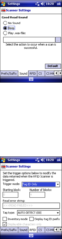
6. In the RFID screen, enter the following settings:
Trigger mode:
Tag ID Only: Select to read only the tag ID.
Read Data Only: Select to read only data from the tag memory.
20
CHAPTER 4: SOCKETSCAN PLUG-IN SOFTWARE 21
Tag ID & Read Data: Select to read both the tag ID and tag
memory.
Starting block: If you selected a Read Data option, enter the number of
the first block you want to begin reading.
Number of blocks: If you selected a Read Data option, enter the
number of blocks you want to read.
Read error string: Enter the string you want your application to display in
case the RFID reader cannot read the tag data.
Tag type: Select the type of RFID tag you want to read. The Auto Detect
setting enables all tag types to be read.
Note: Choosing a specific tag may result in a longer read range and faster
read.
Inventory mode: Select for the RFID reader to read all tags present in an
RFID field, if supported by the tag type.
Display tag ID prefix: Select to display the RFID tag ID prefix with each
tag ID. The prefix indicates the tag type.
Displayable characters only: Select for the RFID reader to read only
displayable characters while reading data from the tag memory.
Otherwise, the RFID reader will also read “filler” symbols used in memory
blocks that aren’t completely filled with data. This option is only available
if you selected a Read Data trigger mode.
7. After selecting all of your Prefix/Suffix, Sound and RFID settings, tap ok.
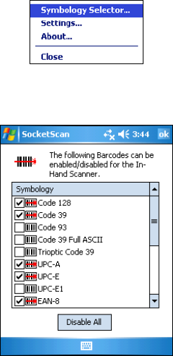
Symbology Selector
If you have the dual-function SOMO 655 RFID Reader-Scan Card 6P2, SocketScan
Plug-in provides an applet that makes it easy to modify which barcode
symbologies the scanner will recognize and attempt to decode. By default, the
scanner is set to recognize several of the most common symbologies.
1. Tap on the SocketScan Plug-in icon at the bottom of the Today
screen.
2. In the pop-up menu, tap Symbology Selector. If SocketScan Plug-in
is currently configured for more than one scanner, then tap In-Hand
Scanner in the submenu that appears.
3. In the screen that appears, use the checkboxes to enable/disable
symbologies. Tap ok.
Note: Enabling all possible symbologies will make the decode process
slightly longer.
Note: If you want to read UPC-A barcodes disable GS1 DataBar (RSS) so
that UPC-A barcodes aren’t mistakenly read as GS1 DataBar.
Note: The RSS symbology is now known as GS1 DataBar.
22
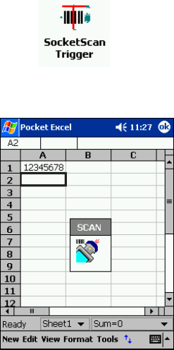
SocketScan Trigger
If you find it inconvenient or impossible to assign or use a hardware button
to trigger the reader, you can install this virtual trigger button that “floats”
on top of the active application.
1. Make sure to do all of the following before using SocketScan Trigger:
Install SocketScan Trigger from the installation CD. The software must
be installed separately from SocketScan Plug-in.
Start SocketScan. Tap Start | Programs | SocketScan Plug-in.
Insert the SOMO 655 RFID Reader Card into your device.
Open the application that you want to receive data.
2. Start SocketScan Trigger. Tap Start | Programs | SocketScan Trigger.
3. The floating trigger button will appear on your screen on top of the
active application.
Drag from the title bar to move the trigger button to a convenient place
on the screen.
Tap the trigger button to activate the RFID reader/barcode scanner.
CHAPTER 4: SOCKETSCAN PLUG-IN SOFTWARE 23
4. A SocketScan Trigger icon will also appear in the menu bar of the Today
screen. Tap on this icon to reveal a pop-up menu with the following
options:
Tap Scan Now to activate the scanner as if you had tapped the
trigger button.
Tap Remove Floating Trigger to remove the trigger button from
the screen but keep the icon handy on the task bar. To restore the
trigger button, tap on the menu bar icon. In the pop-up menu, tap
Launch Floating Trigger.
Tap About to view SocketScan Trigger version information.
Tap Close SocketScan Trigger to close the application completely.
From this state, the SocketScan trigger can only be launched from the
Programs page.
24
DUAL DEVICE SUPPORT
SocketScan v7.2.4.0 and later supports the simultaneous use of two Socket
data collection devices with the same computer. This enables you to use the
SOMO 655 RFID Reader Card with a Socket Bluetooth barcode scanner on
the same computer.
Note: SocketScan Plug-in can capture data from only one cordless scanner at
a time.
Simply connect or plug in each device you plan to use as you normally
would.
The functionality of each device is the same, and no extra configuration is
required.
You can configure each device separately. In the SocketScan Plug-in menu,
tap on the appropriate device to configure its settings.
CHAPTER 4: SOCKETSCAN PLUG-IN SOFTWARE 25
4 | RFID Demo
This chapter explains how to use the Socket Mobile RFID
Demo application with the SOMO 655 RFID Reader Card to
perform the following:
Read an RFID Tag.
Enable Loop Mode.
Select Tag Type.
Advanced – Write to Tag.
Before you begin using the Socket Mobile RFID Demo application, make sure
you have done the following:
Installed the RFID Demo application onto your device, following the same
software installation procedure described in Chapter 2.
Inserted the SOMO 655 RFID Reader Card into your device.
When you use this application, you should only trigger the RFID Reader
Card by tapping on the Select Tags or Read Tag button on the RFID
Demo screen.
26
Read an RFID Tag
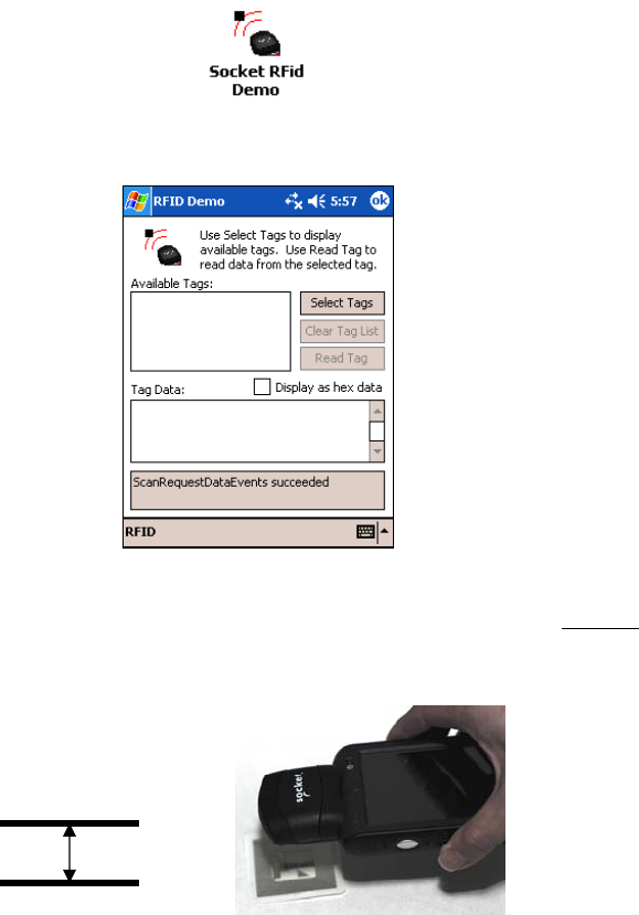
1. Start RFID Demo. Tap Start | Programs | RFID Demo.
2. The main screen of RFID Demo will appear with blank fields.
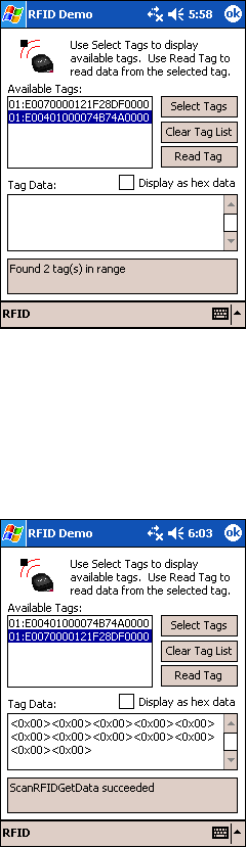
3. Hold the device in the correct position to read an RFID tag, as described in
Chapter 2. Hold the device so the SOMO 655 RFID Reader Card is parallel
to and directly above the tag, at most 2.0 inches above the tag.
Parallel,
3.0 inches (7.6 cm)
maximum
4. Tap Select Tags.
CHAPTER 5: RFID DEMO 27
5. Tag ID(s) should appear in the Available Tags field. Additionally, the
bottom of the screen will report the number of RFID tags found in range.
6. In the Available Tags field, tap to highlight the RFID tag you wish to read,
then tap Read Tag.
7. After the SOMO 655 RFID Reader Card reads the tag, Tag Data will
appear. If desired, check Display as hex data to view the data in
hexadecimal format.
28
Enable Inventory and Loop Modes
The SOMO 655 RFID Reader Card has four reading modes, based on different
combinations of inventory mode and loop mode. The chart below shows the
results of enabling or disabling the modes.
Tag Select
Mode
Loop
Mode
Inventory
Mode Description
One tag Disabled Disabled Selects the first tag in RF field
One tag
continuously Enabled Disabled
Selects the first tag continuously (the same tag ID
will be returned as long as the tag remains in the
RF field.
All tags
present Disabled Enabled
Inventory mode: returns the tag IDs of all tags in
the RF field and then reports when there are no
more tags.
All tags
continuously Enabled Enabled
Returns the tag IDs of all tags in the RF field. It
does not repeat a tag ID unless the tag goes out
and then re-enters the RF field.
Note: Not all tag types are readable in Inventory Mode.
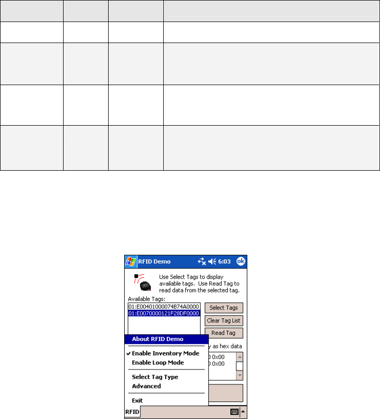
1. In the main screen of RFID Demo, tap RFID at the bottom of the screen. In
the pop-up menu, select adjust the Inventory Mode and/or Loop Mode
settings as desired.
2. After selecting the desired settings, tap Select Tags. The SOMO 655 RFID
Reader Card will search for tags in range, according to your settings.
CHAPTER 5: RFID DEMO 29
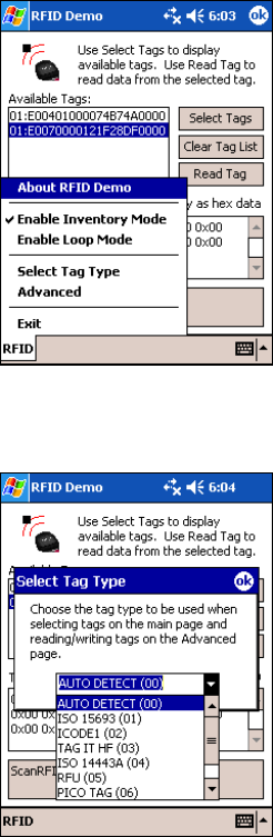
Select Tag Type
1. In the main screen of Socket Mobile RFID Demo, tap RFID at the bottom
of the screen. In the pop-up menu, tap Select Tag Type.
2. In the Select Tag Type dialog box, use the drop-down menu to select the
tag type. Tap ok.
Note:
Tag selection response time is longer with Auto Detect than for specific
tag types. If Auto Detect is not selected, only the type of tags selected
can be read or written to.
Auto Detect will search for tag types 01 to 04. Pico Tag (06) must be
selected in order to read tag ID.
30
ADVANCED: Write to Tag
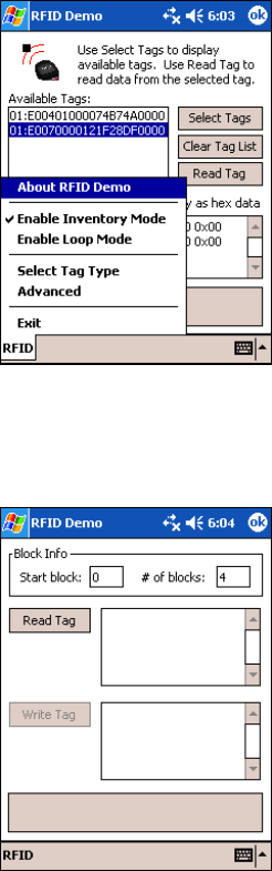
1. In the main screen of Socket Mobile RFID Demo, tap RFID at the bottom
of the screen. In the pop-up menu, tap Advanced.
2. Use the next screen to read and write data in specific blocks of an RFID
tag. Enter the number of the starting block and number of blocks you
would like to read.
3. Hold the Pocket PC in the correct position to read RFID tags — parallel to
the tag and directly above it, at most 2.0 inches above. Tap Read Tag.
CHAPTER 5: RFID DEMO 31
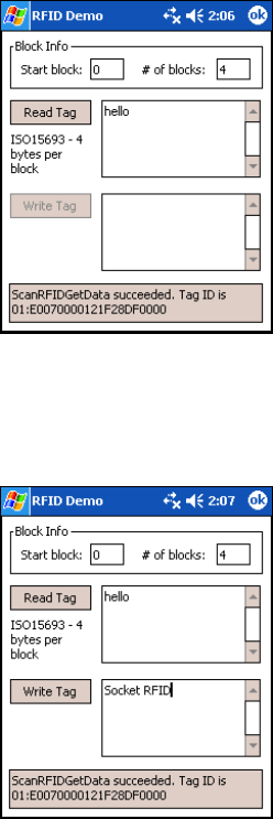
4. RFID Demo will report any data saved to the RFID tag, as well as the type
of tag and number of bytes per block. The bottom of the screen will
report the read status and tag ID.
5. To write data to the tag, enter text into the bottom field. The type and
amount of text that can be written varies depending on your tag type.
After entering text, hold the Pocket PC in the correct reading/writing
position and tap Write Tag.
Note:
The number of characters in the Write Tag field must match the
number of bytes per block multiplied by the number of blocks, or an
error will occur.
See Appendix B to find out the type and amount of text that can be
written to your tag.
The most common cause of write failures is either an incorrect “start
block” or number of blocks.
32
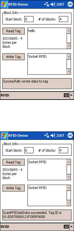
6. After writing data to the tag, the bottom of the screen will report the
write status.
7. To verify that the data was written successfully to the tag, hold the device
in the correct reading/writing position, and tap Read Tag.
8. To close the advanced screen, tap ok.
CHAPTER 5: RFID DEMO 33
34
Appendix A
Product Specifications
Physical Characteristics
CompactFlash Card Size: 1.4 x 1.68 x 0.20 inches (36 x 42.7 x 5.0 mm)
Reader/Scanner Head Size: 1.8 x 1.9 x 0.83 inches (45 x 49 x 21 mm)
Weight:
6E2/6E2Rx: 1.1 oz. (31 g)
6P2: 1.3 oz (37 g)
Environmental:
Operating Temperature: -10 to +50°C (-4 to +122°F)
Storage Temperature: -40 to +70°C (-40 to +158°F)
Humidity: 5-95% RH non-condensing
Ambient Light for Barcode Scanning (6P2 only):
Sunlight: 10,000 ft candles (107,640 lux) Artificial light: 450 ft candles (4,844 lux)
Electrical Specifications:
Power Consumption (3.3 V):
6E2/6E2Rx: Standby: 11mA (36 mW),
Reading/Writing RFID: 52 mA (171 mW)
6P2: Standby: 11 mA (36 mW) typical
Scanning barcodes: 72 mA (238 mW) typical
Reading/Writing RFID: 52 mA (171 mW)
Also operates at 5 V
Laser Power (6P2): 1.7 mW (±0.2 mW)
Compatibility: Windows COM port
Operating System Support:
Windows Mobile 6 Classic/Professional
Windows Mobile 2003, 2003SE, 5.0 for Pocket PC
Certification: FCC: Part 15, Class B, CE: EN55024:1998, C-TICK: s.182
RFID Characteristics:
Frequency: 13.56 MHz (HF)
APPENDIX A: PRODUCT SPECIFICATIONS 35
Maximum Read Range: ~ 3.0 inches for ISO15693 tags, depending on tag antenna size
HF RFID Tags Supported
ISO15693: ICode SL2, LRI512, my-d, Tag-It HF-I
Proprietary: ICode SL1, PicoTag (no anti-collision), Tag-It HF
ISO14443A: Mifare (Tag ID only), Mifare Ultralight (no anti-collision)
Barcode Scanner Characteristics (6P2 only):
Symbology Support: Chinese 2 of 5, Codabar, Code 11, Code 128, Code 39, Code 93,
Discrete 2 of 5, GS1-128, GS1 DataBar (formerly RSS), Interleaved 2 of 5, MSI,
UPC/EAN
Scan Repetition Rate: 100 scans/sec (bidirectional)
Optical Resolution: 0.004 in. minimum/barcode element width (X Dimension)
Print Contrast: Minimum 25% absolute dark/light reflectance (MRD) measured at 650
MRD
Scan Angle: Wide (default): 47° ±3°, Narrow: 35° ±3°
Decode Zone: 1.5 to 45+ inches (3.8 to 144+ cm)
36
Appendix B
HF RFID Standards and Tag Descriptions
ISO15693
The ISO/IEC 15693 standard was developed for “Contactless Vicinity Cards”. Adopted
in 1998, ISO15693 has significantly enabled global acceptance of 13.56MHz RFID
technology. Based on contributions by Texas Instruments and Philips, ISO/IEC 15693
is largely a superset of the features and specifications of the Tag-it HF and I·Code1
products, respectively.
ISO15693-1: Defines the physical characteristics of a credit card transponder.
ISO15693-2: Specifies the 13.56MHz air interface and modulation methods that
accommodate regulatory bodies worldwide.
ISO15693-3: Specifies the command protocol and anti-collision method for data
exchange between tags and readers.
The ISO15693 “standard” permits tags to be manufactured that support optional
and custom commands, and that have custom memory structures, sizes and
architectures. The SkyeRead family of RFID readers fully supports all four (4) IC
manufacturers that offer ISO/IEC 15693 compatible tags.
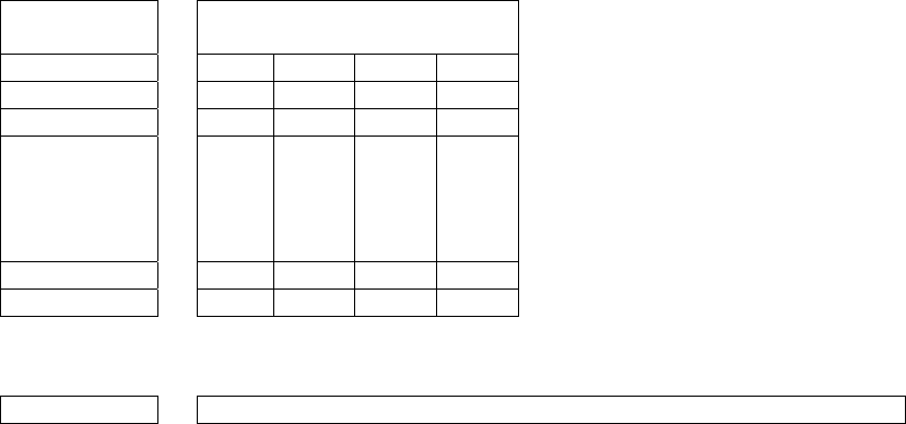
Tag-It HF-I ISO15693 (Texas Instruments)
The complete Tag-It HF-I specification can be found in the Texas Instruments
publication titled “Tag-It HF-I Transponder Inlays Reference Guide”.
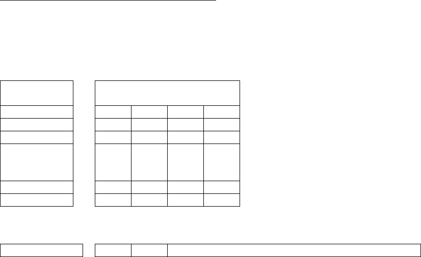
Figure 1 - Memory Structure of the Tag-It HF-I
2K bits (256 bytes) of user memory is available for read/write.
Block # 32 bits
(4 bytes per block)
0 (0x00)
1 (0x01)
2 (0x02)
.
.
.
.
.
.
.
.
.
.
.
.
.
.
.
62 (0x3E)
63 (0x3F)
The user can permanently lock any
block.
Once a block is locked, it can not
be unlocked.
A 64-bit ID (factory programmed) uniquely identifies each Tag-It HF-I chip.
TID 0xE0 0x07 Unique Tag ID - 48 bits (6 bytes)
APPENDIX B: HF RFID STANDARDS AND TAG DESCRIPTIONS 37
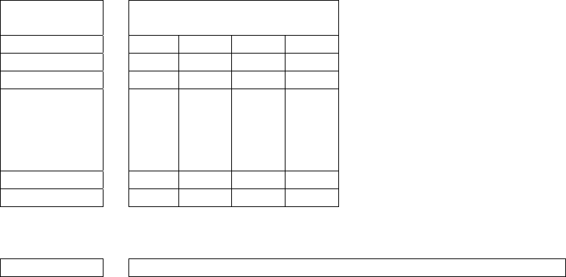
I·Code SLI ISO15693 (Philips)
The complete I·Code SLI specification can be found in the Philips publication titled
“I·Code SLI Smart Label IC SL2 ICS20 Functional Specification”.
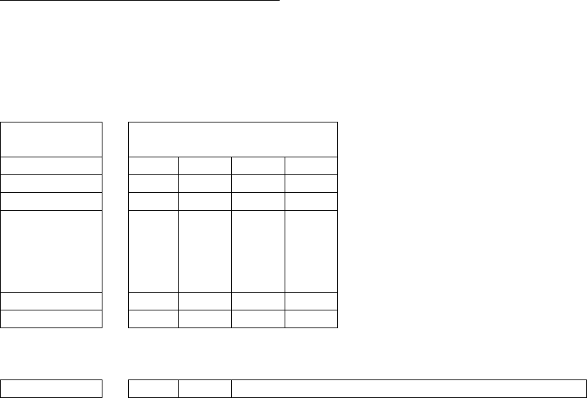
Figure 1 - Memory Structure of the I·Code SLI (version SL2 ICS20)
896 bits (112 bytes) of user memory is available for read/write.
Block # 32 bits
(4 bytes per block)
0 (0x00)
1 (0x01)
2 (0x02)
.
.
.
.
.
.
.
.
.
.
.
.
.
.
.
26 (0x1A)
27 (0x1B)
The user can permanently
lock any block.
Once a block is locked it can
not be unlocked.
A 64-bit ID (factory programmed) uniquely identifies each I·Code SLI chip (SL2 ICS20).
TID 0xE0 0x04 0x01 Unique Tag ID 40 bits (5 bytes)
my-d SRF55VxxP ISO15693 (Infineon)
The complete my-d SRF55VxxP specification can be obtained from Infineon.
Figure 2 - Memory Structure of the my-d SRF55V02P
29 blocks of 8 bytes = 232 bytes (1856 bits) of user memory is available for read/write.
Block # 64 bits
(8 bytes per block)
3 (0x03)
4 (0x04)
5 (0x05)
.
.
.
.
.
.
.
.
.
.
.
.
.
.
.
.
.
.
.
.
.
.
.
.
.
.
.
30 (0x1E)
31 (0x1F)
The user can
permanently lock
any block
Once a block is
locked it can not
be unlocked.
38
A 64-bit ID (factory programmed) uniquely identifies each my-d SRF55V02P chip.
TID 0x6
0
0x05 0x02 Unique Tag ID - 40 bits (5 bytes)
Figure 4 - Memory Structure of the my-d SRF55V10P
125 blocks of 8 bytes = 1000 bytes (8000 bits) of user memory is available for
read/write.
Block # 64 bits
(8 bytes per block)
3 (0x03)
4 (0x04)
5 (0x05)
.
.
.
.
.
.
.
.
.
.
.
.
.
.
.
.
.
.
.
.
.
.
.
.
.
.
.
126 (0x7E)
127 (0x7F)
The user can
permanently lock
any block
Once a block is
locked it can not
be unlocked.
A 64-bit ID (factory programmed) uniquely identifies each my-d SRF55V10P chip.
TID
0x6
0
0x05 0x00 Unique Tag ID - 40 bits (5 bytes)
APPENDIX B: HF RFID STANDARDS AND TAG DESCRIPTIONS 39
LRI512 ISO15693 (ST Microelectronics)
The full LRI512 specification was included in “LRI512 Memory TAG IC 512 bit High
Endurance EEPROM 13.56MHz, ISO 15693 Standard Compliant with E.A.S.” by ST
Microelectronics.
Figure 5 - Memory Structure of the STM LRI512
512 bits (64 bytes) of user memory is available for read/write.
Block # 32 bits
(4 bytes per block)
3 (0x03)
4 (0x04)
5 (0x05)
.
.
.
.
.
.
.
.
.
.
.
.
.
.
.
14 (0x0E)
15 (0x0F)
The user can permanently lock any
block.
Once a block is locked it can not
be unlocked.
A 64-bit ID (factory programmed) uniquely identifies each STM LRI512 chip.
TID 0xE0 0x02 Unique Tag ID 48 bits (6 bytes)
40
Tag-it HF
The first 13.56MHz RFID IC that Texas Instruments developed was the Tag-it HF. Still
in high volume production, Tag-it HF is widely used in applications globally and has
an existing installed base of millions of tags. The Tag-it HF uses a protocol air
interface that is proprietary to Texas Instruments.
By contrast, the Tag-it HF-I was released by Texas Instruments in 2001 is compatible
with ISO/IEC 15693 parts -2 and -3. The host application developer should be aware
of the distinction between the Tag-it HF and the Tag-it HF-I.
Figure 7 - Memory Structure of the Tag-it HF
256 bits (32 bytes) of user memory is available for read/write.
Block # 32 bits
(4 bytes per block)
0 (0x00)
1 (0x01)
2 (0x02)
.
.
.
.
.
.
.
.
.
.
.
.
.
.
.
6 (0x06)
7 (0x07)
The user can permanently lock any
block.
Once a block is locked it can not be
unlocked.
A 32-bit ID (factory programmed) uniquely identifies each Tag-it HF chip.
TID Unique Tag ID 32 bits (4 bytes)
The complete Tag-it HF specification can be obtained from Texas Instruments.
APPENDIX B: HF RFID STANDARDS AND TAG DESCRIPTIONS 41
I·Code1
The first long range 13.56MHz RFID IC that Philips released was the I·Code1 (SL1).
Still in high volume production, I·Code1 (SL1) is still widely used in applications
globally and has an existing installed base of millions of tags. The I·Code1 (SL1) uses
a protocol and air interface that is proprietary to Philips.
By contrast, the I·Code SLI (SL2), released by Philips in 2002, is fully compatible with
ISO/IEC 15693 parts -2 and -3. The host application developer should be explicitly
aware of the distinction between the I·Code1 (SL1) and the I·Code SLI (SL2).
Figure 8 - Memory Structure of the I·Code1 (version SL1 ICS30 01)
512 bits (64 bytes) of user memory is available for read/write.
Block # 32 bits
(4 bytes per block)
3 (0x03)
4 (0x04)
5 (0x05)
.
.
.
.
.
.
.
.
.
.
.
.
.
.
.
14 (0x0E)
15 (0x0F)
The user can permanently lock
any block.
Once a block is locked it cannot
be unlocked.
A 64-bit ID (factory programmed) uniquely identifies each I·Code1 chip.
TID Unique Tag ID 64 bits (8 bytes)
42
PicoTag
Inside Contactless (formerly Inside Technologies) makes a contactless RFID product
series called the PicoTag. There are two different sizes of PicoTag memories, 2K and
16K. There are two different modes of operation, plain and secure.
Figure 9 - Memory Structure of the PicoTag 2K
29 blocks of 8 bytes = 232 bytes (1856 bits) of user memory is available for
read/write.
Block # 64 bits
(8 bytes per block)
3 (0x03)
4 (0x04)
5 (0x05)
.
.
.
.
.
.
.
.
.
.
.
.
.
.
.
.
.
.
.
.
.
.
.
.
.
.
.
30 (0x1E)
31 (0x1F)
The user can
permanently
lock any block
Once a block is
locked it can not
be unlocked.
A 64-bit ID (factory programmed) uniquely identifies each PicoTag chip.
TID Unique Tag ID 64 bits (8 bytes)
Note: Only the tag ID can be read by the SOMO 655 RFID Reader-Scan Card.
APPENDIX B: HF RFID STANDARDS AND TAG DESCRIPTIONS 43
ISO14443
ISO/IEC 14443 is a 4-part RFID standard for short-range “Contactless Proximity
Cards”. Adopted in 1999 and 2000, ISO14443 has become the worldwide standard
for cashless payment and contactless stored value applications.
ISO14443-1 defines the physical characteristics of an RFID card.
ISO14443-2 specifies two types (A and B) of 13.56MHz air interface and
modulation methods used for communication between tags and readers.
ISO14443-3 specifies the anti-collision method for selecting one tag among
many.
ISO14443-4 defines the high-level protocol and method for data exchange
between tags and readers.
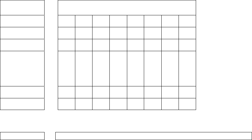
14443-A Mifare Standard 4K (Philips)
The Mifare chip from Philips is used in millions of secure contactless applications
since it was introduced in 1995.
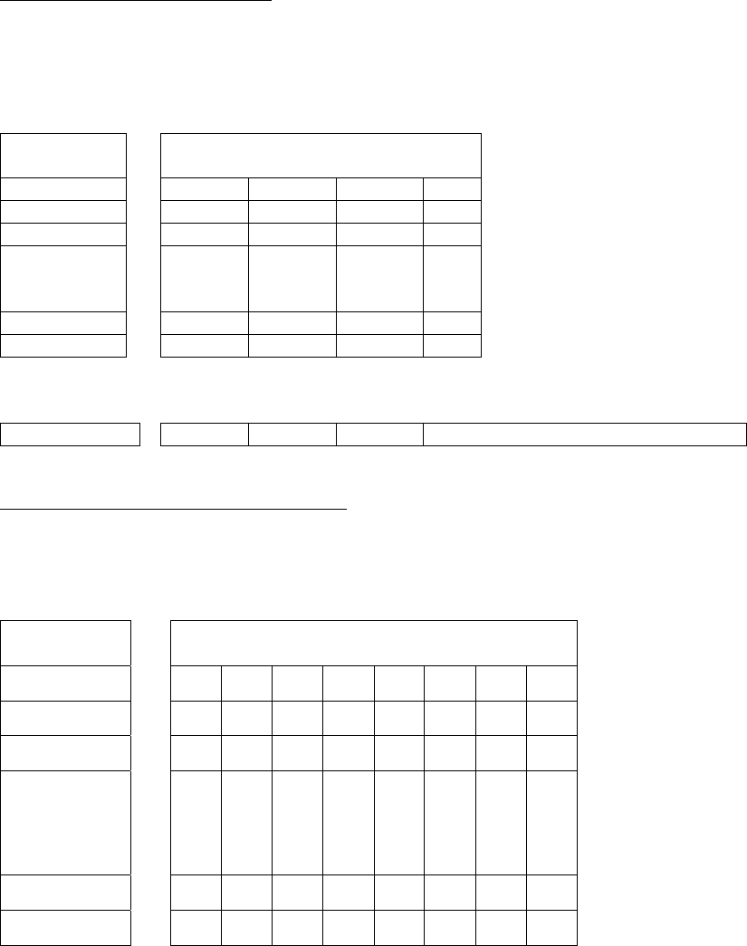
Figure 10 - Memory Structure of the Mifare Standard 4K (MF1 IC S70)
BYTE
BLOCK SECTOR 15 14 13 12 11 10 09 08 07 06 05 04 03 02 01 00
0 Serial Number Check
Byte Manufacturer Data
1 Data
2 Data
3
0
Key A Lock Bits Key B
4 Data
5 Data
6 Data
7
1
Key A Lock Bits Key B
.
.
.
.
.
.
.
.
.
60 Data
61 Data
62 Data
63
15
Key A Lock Bits Key B
The complete Mifare specification can be obtained from the Philips publication
“Mifare Standard 4 kByte Card IC MF1 IC S70” dated October 2002.
Note: Only the tag serial number can be read by the SOMO 655 RFID Reader Card.
44
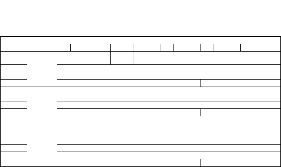
Mifare Ultralight (Philips)
The complete Mifare Ultralight specification can be obtained from the Philips
publication “Mifare Ultralight Contactless Single-trip Ticket IC MF0 IC U1 Functional
Specification” dated March 2003.
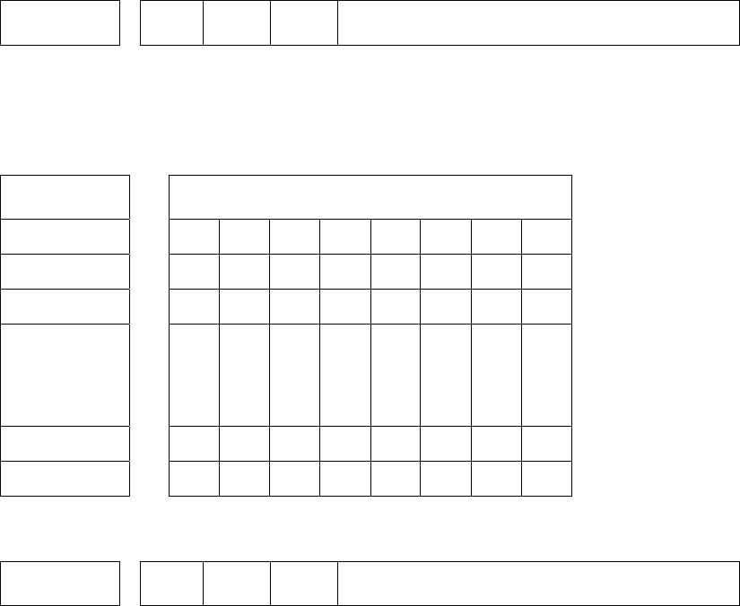
Figure 11 - Memory Structure of the Mifare Ultralight (MF0 IC U1)
Byte
Block
00 01 02 03
0 SN0 SN1 SN2 BCC0
1 SN3 SN4 SN5 SN6
2 BCC1 Internal Lock 0 Lock 1
3 OTP 0 OTP 1 OTP 2 OTP 3
4 Data 0 Data 1 Data 2 Data 3
.
.
.
.
.
.
15 Data 44 Data 45 Data 46 Data 47
System Area
User Area
Note: Only the tag serial number can be read by the SOMO 655 RFID Reader Card.
APPENDIX B: HF RFID STANDARDS AND TAG DESCRIPTIONS 45
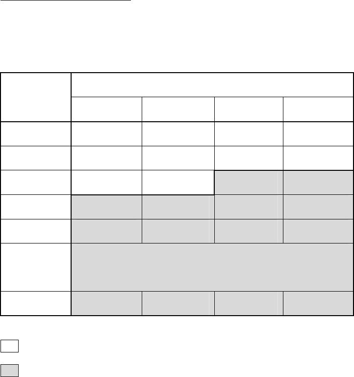
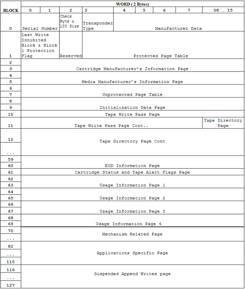
LTO CM 14443-A (LTO) The LTO-CM is compliant with ISO14443-A air interface.
Figure 12 - Memory Structure of the LTO CM
128 blocks of 32 bytes = 4096 bytes (32768 bits) of user memory is available for read/write.
Note: Only the tag serial number can be read by the SOMO 655 RFID Reader-Scan
Card.
46 | APPENDIX C: BARCODE LABEL SPECIFICATIONS
Appendix C
Barcode Label Specifications
All barcode symbols/labels should satisfy the appropriate AIM Uniform Symbology
Specification.
Background Substrate:
The barcode symbol should be printed on material (media) that is reflective and has
a matte (not glossy) finish. A background diffuse reflectance of at least 70% to 80%
is desirable for optimum contrast. Retro-reflective media should be used to obtain
decode distances greater than 36 inches.
Ink Color and Type:
The inked bars should not exceed 25% reflectance at the wavelength that is being
used for reading, whether printed with black ink or colored ink. The reflectance
value should not vary more than 5% within the same character.
Voids and Specks:
The code should be printed clearly, free of voids, specks, blemishes and lines that
could “fool” the scanner. Specks or blemishes in the white spaces, or false or
missing bar sections could be interpreted by the reading equipment as part of the
code. Generally, the width of such flaws is more serious than the height. Code
symbols/ labels should be rejected if these defects are present.
Definition:
The bars in the barcode symbol should be well defined. Their edges should not be
rough or fuzzy, so that the bars and spaces have the proper widths intended for the
barcode symbology used.
Contrast:
Background reflectance (that of the substrate on which the codes are printed)
should always provide a good contrast relative to the ink reflectance (that of the
code bars). The difference between the two should be at least 37.5% at the
wavelength used for reading.
Tolerance:
The ratio of the widths of bars and spaces in a barcode symbol must conform to the
appropriate AIM barcode specifications and can cause problems if not correct
throughout the barcode. Problems can occur when bar edges are smeared or rough,
or when they exhibit voids.

Appendix D
Enabling or Disabling Symbologies
All Socket Mobile barcode scanning products are preset to automatically detect and
decode (autodiscriminate) the most common barcode symbologies. Refer to the table
on the next page to determine which symbologies and parameters are enabled by
default. If you would like to change your symbology settings, you can use either of
two methods, depending on which device you are using and which settings you want
to change.
Note: If more symbologies are enabled, the scanner must work harder to search
through all possible combinations. This may make the decoding process slightly
longer.
OPTION 1: Symbology Selector
If you are using a Windows Mobile-based device, you can quickly enable and disable
any of the seventeen most popular symbologies by using the SocketScan Symbology
Selector. Refer to Chapter 2 for instructions.
Note: The length of some symbologies will change after Symbology Selector is used.
Refer to the table on the next page.
OPTION 2: Scan Programming Barcodes
If you want to modify an option not included in Symbology Selector, you can scan
programming barcodes to configure your SOMO 655 RFID Reader-Scan Card. There
are a variety of programming barcodes available that let you enable/disable
symbologies as well as configure special features (e.g., specify barcode lengths,
transmit check digits, recognize supplementals, etc.).
To obtain the programming barcodes, download the Programming Guide online
from http://www.socketmobile.com/support/downloads
WARNING!
When scanning programming barcodes with the SOMO 655 RFID
Reader-Scan Card 6P2, do not scan any barcodes that set
communication protocols, or the card will be disabled and must
be returned to Socket Mobile for reprogramming.
APPENDIX D: ENABLING/DISABLING SYMBOLOGIES | 47

48 | APPENDIX D: ENABLING OR DISABLING SYMBOLOGIES
Table 1. Default Symbologies and Settings of the SOMO 655 RFID Reader-Scan Card
Symbology Default Length
Length with
Symbology
Selector
UPC-A Enabled N/A N/A
UPC-E Enabled N/A N/A
UPC-E1 Disabled N/A N/A
EAN-8 Enabled N/A N/A
EAN-13 Enabled N/A N/A
Supplementals Disabled N/A N/A
Transmit Check Digit Enabled N/A N/A
Bookland EAN Disabled N/A N/A
Code 128 - All Enabled Any Any
Code 39 Enabled 2 to 55 2 to 55
Trioptic Code 39 Disabled 2 to 55 2 to 55
Code 39 Full ASCII Disabled 2 to 55 2 to 55
Transmit Check Digit Disabled N/A N/A
Code 93 Disabled 4 to 55 2 to 55
Interleaved 2 of 5* Enabled 14 Only 2 to 55
Transmit Check Digit Disabled N/A N/A
Discrete 2 of 5* Disabled 12 Only 2 to 55
Codabar Disabled 5 to 55 2 to 55
MSI Plessey* Disabled 6 to 55 2 to 55
Transmit Check Digit Disabled N/A N/A
*WARNING: Setting the length to “Any” may lead to inaccurate decodes in these symbologies
Appendix E
Laser Decode Zone
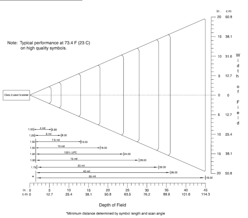
The decode zone for the Class 2 laser in the SOMO 655 RFID Reader-Scan Card 6P2 is
shown below. The minimum element width (“X Dimension” or barcode “size”) is the
width in thousandths of an inch (mils) of the narrowest element (bar or space) in the
symbol. The figures shown are the typical scanning distances (depths of field) for
selected barcode sizes. The maximum usable length of a barcode symbol (Width of
Field) at any given range is also shown below.
Class 2 Laser Decode Zone
APPENDIX E: LASER DECODE ZONE | 49
Appendix F
Troubleshooting
For help on SocketScan Plug-in on a Windows Mobile-based device, tap Start | Help.
SYMPTOM:
I get the “No Card Detected” icon in the task tray and can’t trigger
the RFID reader or scan any barcodes.
POSSIBLE REASON SOLUTION
Your device does not
recognize the card.
Make sure the card is inserted properly.
Push it in all the way. If necessary, remove
and reinsert.
SYMPTOM:
When I try to read an RFID tag, no data appears on my screen.
POSSIBLE REASON SOLUTION
You are holding the RFID
Reader Card in the wrong
position.
Hold the device so the RFID Reader Card is
parallel to and directly above the RFID tag,
at most 2.5 inches above the tag.
The RFID tag antenna is
broken or incorrectly
formatted.
Try reading another RFID tag that is
correctly formatted.
The tag type may be disabled. Use RFID Demo to determine the tag type.
If needed, reconfigure the RFID Reader Card
for the correct tag type.
SYMPTOM:
When I press the trigger button, nothing happens.
POSSIBLE REASON SOLUTION
You programmed the trigger
button incorrectly.
Test the button by assigning a different
program to it and make sure it works
properly.
50 | APPENDIX F: TROUBLESHOOTING

APPENDIX G: TECHNICAL SUPPORT | 51
Appendix G
Technical Support
If you have trouble installing or using the SOMO 655 RFID Reader Card, Socket has
different support options to help you.
Online Knowledge Base: Search for articles, Frequently Asked Questions or Hot
Topics any time, day or night. http://support.socketmobile.com/faq
Online Requests: Register your product and submit a question to our Technical
Support Team. http://support.socketmobile.com/
By Phone: Contact our Tier 1 Technical Support by calling either:
USA & Canada Toll-Free: 800-279-1390
Direct: +1- 510-933-3020
Please refrain from disassembling the card. Disassembly of this device will void the
product warranty.

Limited Warranty
Socket Mobile, Inc. warrants this product against defects in material and workmanship, under normal use and
service, for one (1) year from the date of purchase.
EXCLUDES: Consumables such as batteries, removable cables, cases, straps, chargers, and SOMO
655-to-PC Card adapters (90 day coverage only)
Incompatibility is not a defect covered by the Socket Mobile warranty. During the warranty period, Socket
Mobile will, at its option, repair or replace the defective product at no charge when furnished with proof of
retail purchase, provided that you deliver the product to Socket Mobile or to an authorized Socket Mobile
Service Center.
The returned product must be accompanied by a return material authorization (RMA) number issued by Socket
Mobile or by an authorized Socket Mobile Service Center. If you ship the product, you must use the original
container or equivalent and you must pay the shipping charges to Socket. Socket Mobile will pay surface
shipping charges back to any location in the contiguous United States. This warranty applies only to the
original retail purchaser and is not transferable.
Socket Mobile may, at its option, replace or repair the product with new or reconditioned parts and the
returned product becomes the property of Socket Mobile. Socket Mobile warrants the repaired or replaced
products to be free from defects in material or workmanship for ninety (90) days after the return shipping
date, or for the remainder of the original warranty period, whichever is greater.
This warranty does not cover the replacement of products damaged by abuse, accident, misuse or
misapplication, nor as a result of service or modification other than by Socket Mobile.
SOCKET MOBILE IS NOT RESPONSIBLE FOR INCIDENTAL OR CONSEQUENTIAL DAMAGES RESULTING FROM
BREACH OF ANY EXPRESS OR IMPLIED WARRANTY, INCLUDING DAMAGE TO PROPERTY AND, TO THE EXTENT
PERMITTED BY LAW, DAMAGES FOR PERSONAL INJURY. THIS WARRANTY IS IN LIEU OF ALL OTHER
WARRANTIES INCLUDING IMPLIED WARRANTIES OF MERCHANTABILITY AND FITNESS FOR A PARTICULAR
PURPOSE.
Some states do not allow limitation of implied warranties, or the exclusion or limitation of incidental or
consequential damages, so that the above limitations or exclusions may not apply to you. This warranty gives
you specific legal rights and you may also have other rights which vary from state to state.
This product may contain fully tested, recycled parts, warranted as if new.
For warranty information, please visit: http://support.socketmobile.com/
52
Limited Software Warranty
LIMITED WARRANTY. SOCKET MOBILE warrants that the original disk or CD ROM is free from defects for 90
days from the date of delivery of the SOFTWARE.
CUSTOMER REMEDIES. The entire liability of SOCKET MOBILE and your exclusive remedy shall be, at the option
of SOCKET MOBILE, either (a) return of the price paid or (b) replacement of the SOFTWARE which does not
meet the SOCKET MOBILE Limited Warranty and which is returned to SOCKET MOBILE with a copy of your
receipt. Any replacement SOFTWARE will be warranted for the remainder of the original warranty period or 30
days, whichever is longer. THESE REMEDIES ARE NOT AVAILABLE OUTSIDE OF THE UNITED STATES OF
AMERICA.
NO OTHER WARRANTIES. SOCKET MOBILE disclaims all other warranties, either express or implied, including
but not limited to implied warranties of merchantability and fitness for a particular purpose, with respect to
the SOFTWARE and the accompanying written materials. This limited warranty gives you specific legal rights.
You may have others which vary from state to state.
NO LIABILITY FOR CONSEQUENTIAL DAMAGES. In no event shall SOCKET MOBILE or its suppliers be liable for
any damages whatsoever (including, without limitation, damages for loss of business profits, business
interruption, loss of business information, or other pecuniary loss) arising out of the use of or inability to use
the SOFTWARE, even if SOCKET MOBILE has been advised of the possibility of such damages. Because some
states do not allow the exclusion or limitation of liability for consequential or incidental damages, the above
limitation may not apply to you.
EXPORT LAW ASSURANCES. You may not use or otherwise export or re-export the SOFTWARE except as
authorized by United States law and laws of the jurisdiction in which the SOFTWARE was obtained. In
particular, but without limitation, none of the SOFTWARE may be used or otherwise exported or re-exported
(a) into (or to a national or resident of) a United States embargoed country or (b) to anyone on the U.S.
Treasury Department’s list of Specially Designated Nationals or the U.S. Department of Commerce’s Table of
Denial Orders. By using the SOFTWARE, you represent and warrant that you are not located in, under control
of, or a national or resident of any such country or on any such list.
GOVERNMENT END USERS. If the SOFTWARE is supplied to the U. S. Government, the SOFTWARE is classified as
“restricted computer software” as defined in clause 52.227-19 of the FAR. The U. S. Government ‘s rights to the
SOFTWARE are as provided in clause 52.227-19 of the FAR.
CONTROLLING LAW AND SEVERABILITY. This License shall be governed by the laws of the United States and
the State of California. If for any reason a court of competent jurisdiction finds any provision, or portion
thereof, to be unenforceable, the remainder of this License shall continue in full force and effect.
53
Regulatory Compliance
This equipment has been tested and found to comply with the limits for a Class B digital device,
pursuant to Part 15 of the FCC rules. This equipment is also CE EN55024:1998 and C-TICK compliant.
These limits are designed to provide reasonable protection against harmful interference when the
equipment is operated in a commercial environment.
This equipment generates, uses, and can radiate radio frequency energy and, if not installed and
used in accordance with the instruction manual, may cause harmful interference to radio
communications. Operation of this equipment in a residential area may cause harmful interference
in which case the user will be required to correct the interference at his or her own expense.
If this equipment does cause harmful interference to radio or television reception, which can be
determined by turning the equipment off and on, the user may try to correct the interference by
doing any of the following:
Reorient or relocate the receiving antenna of the radio or television.
Increase the distance separating the equipment and the receiver.
Connect the equipment to an outlet on a different branch circuit than that of the receiver.
Consult the dealer or an experienced radio/TV technician for help.
The user may find the following booklet helpful: How to Identify and Resolve Radio-TV Interference
Problems. This booklet is available from the U.S. Government Printing Office, Washington, D.C.
20402
LASER DEVICES: The Socket barcode scanning product (version 6P2) described in this User’s Guide
contains a Symbol SE955 laser scan engine.
For the Class 2 version of this engine, the following applies:
Complies with 21SOMO 655R1040.10 and 1040.11 except for deviations pursuant to Laser Notice
No. 50, dated July 26, 2001.”
Caution: Use of controls, adjustments or performance of procedures other than those
specified herein may result in hazardous laser light exposure.
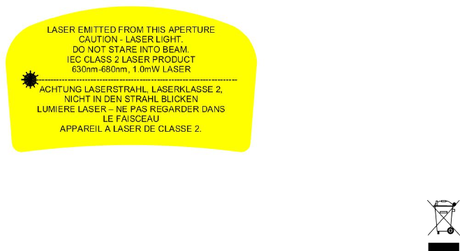
Class 2 laser scanners use a low power, visible light diode. As with any very bright light source,
such as the sun, the user should avoid staring directly into the light beam. Momentary exposure
to a Class 2 laser is not known to be harmful. A label such as the one below should appear on the
end product.
Example of Class 2 Laser Warning Label
PRODUCT DISPOSAL: Your device should not be placed in municipal waste. Please check local
regulations for disposal of electronic products.
54
1/2010 Printed in U.S.A.