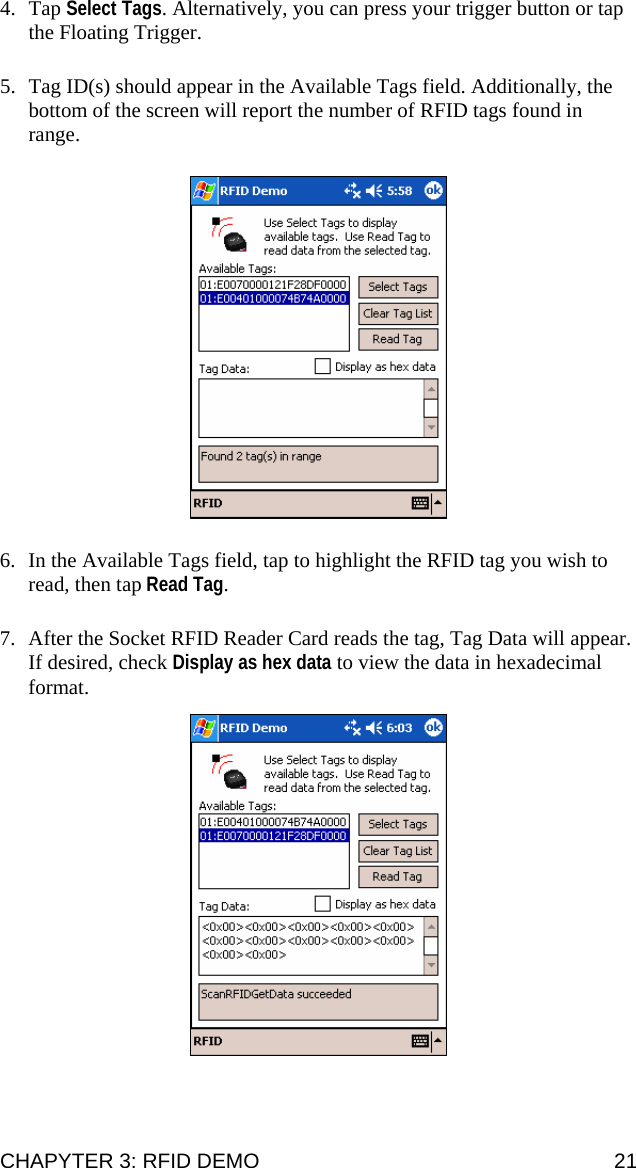
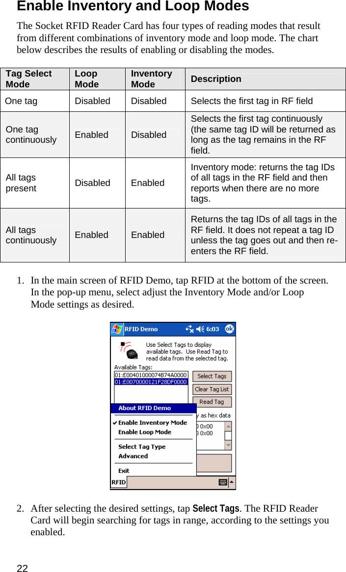
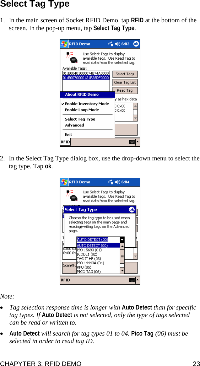
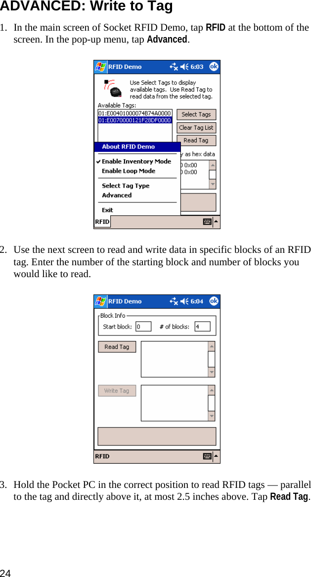
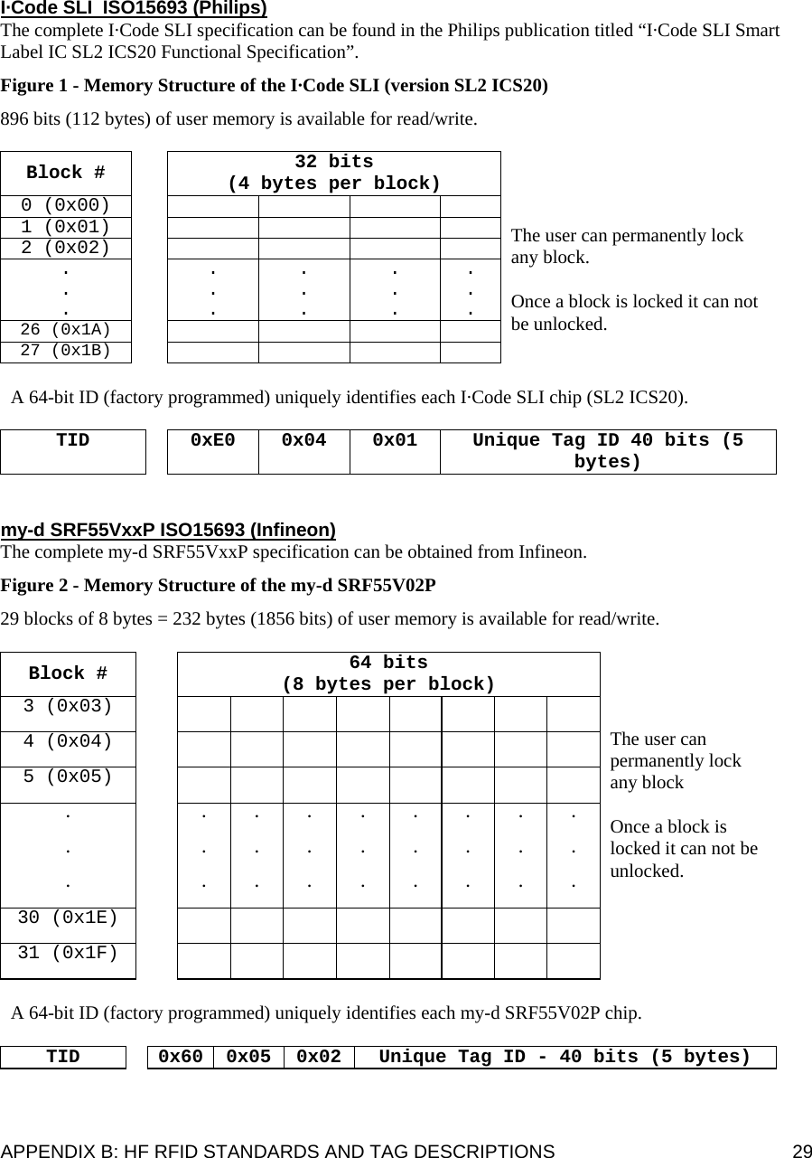
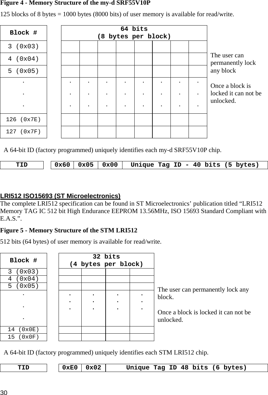
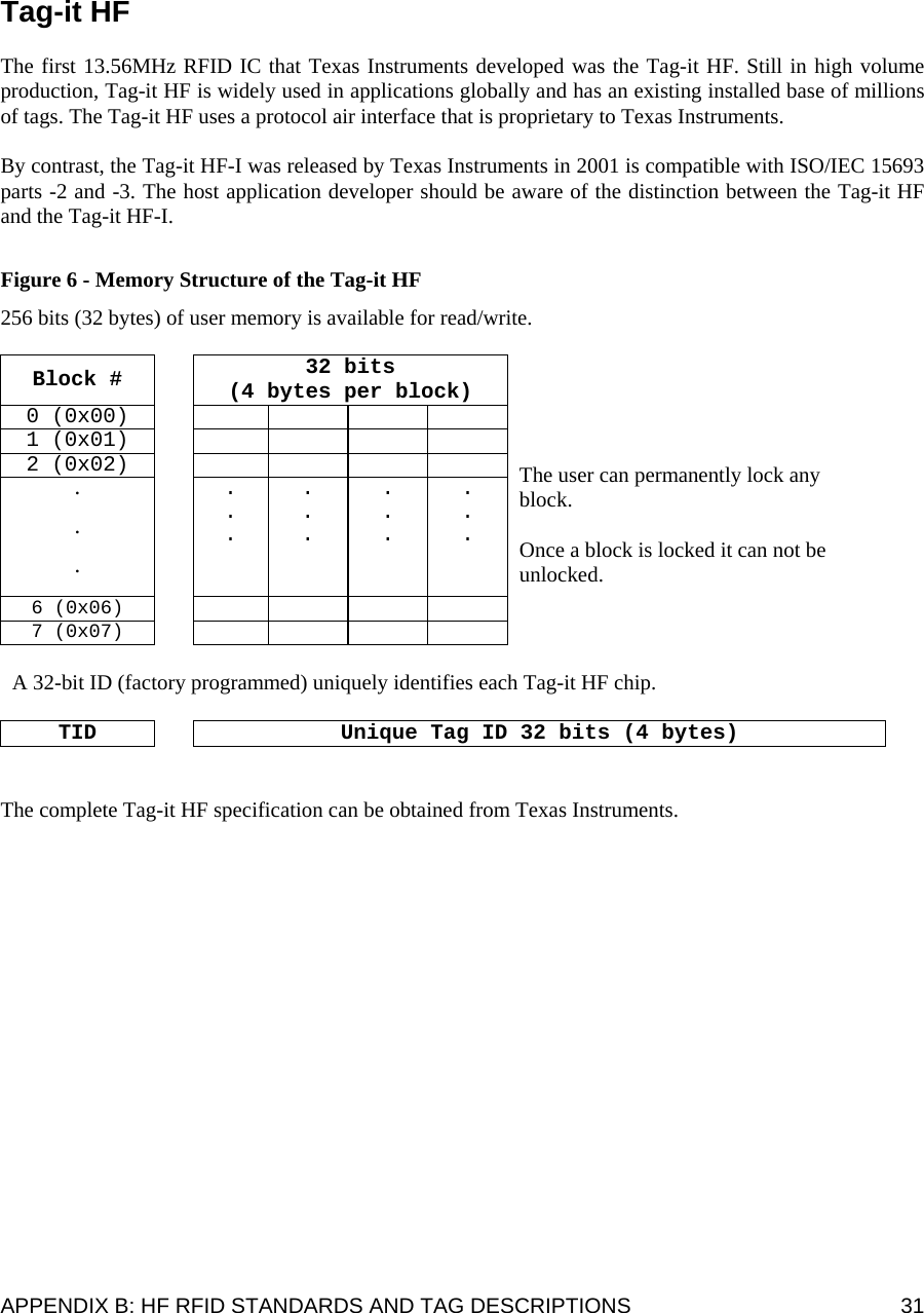
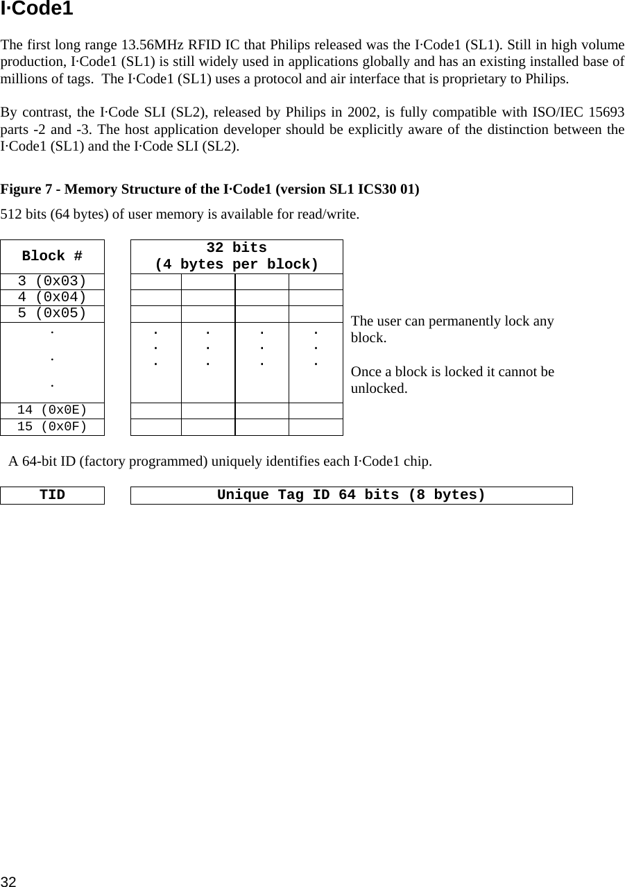
Socket Mobile RFID001 CompactFlash rfid Card User Manual Socket RFID Reader Card User s Guide

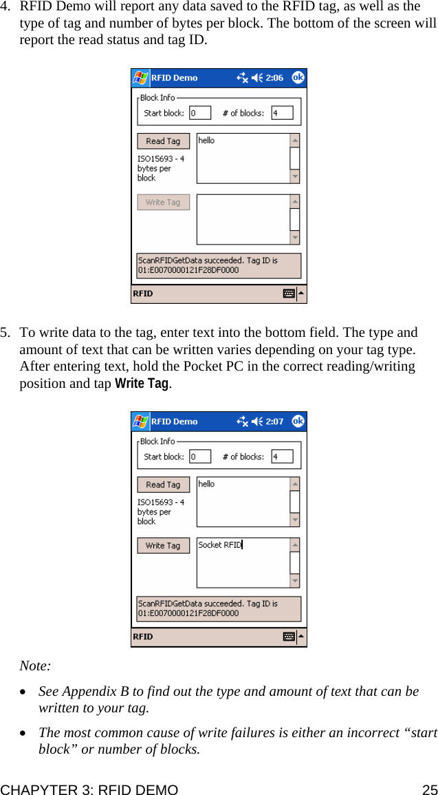
Socket Mobile, Inc. CompactFlash rfid Card Socket RFID Reader Card User s Guide

Manual

CF RFID Reader Card™ CompactFlash Card with Integrated High Frequency RFID Reader/Writer for Pocket PC 2003   User’s Guide
5/2005  Document # 6410-00260 B   Copyright Notice  Copyright © 2005 Socket Communications, Inc. All rights reserved.  Socket, the Socket logo and Mobility Friendly are registered trademarks of Socket Communications, Inc. CF RFID Reader Card, RFID Demo, SocketScan, and SocketScan Trigger are registered trademarks or trademarks of Socket Communications, Inc. All other brand and product names are trademarks of their respective holders.  Reproduction of the contents of this manual without the permission of Socket Communications is expressly prohibited. Please be aware that the products described in this manual may change without notice.  Feel free to contact SOCKET COMMUNICATIONS at:  Socket Communications, Inc. 37400 Central Court Newark, CA 94560  Other than the above, Socket Communications can assume no responsibility for anything resulting from the application of information contained in this manual.  Please refrain from any applications of the Socket CF RFID Reader Card that are not described in this manual. Please refrain from disassembling the CF RFID Reader Card. Disassembly of this device will void the product warranty.  You can track new product releases, software updates and technical bulletins by visiting Socket’s web page at: www.socketcom.com.
Table of Contents  COPYRIGHT NOTICE 2 1 | INTRODUCTION 4 About the Software 4 System Requirements 5 Package Contents 5 Product Registration 5 2 | SETUP FOR WINDOWS MOBILE 6 STEP 1: Uninstall Other Scanning Software 7 STEP 2: Install the Software 8 STEP 3: Insert the CF RFID Reader Card 10 STEP 4: Start SocketScan 10 STEP 5: Assign a Trigger Button 11 STEP 6: Read Tag ID into a Windows Program 12 OPTIONAL: Configure Prefix/Suffixes 15 OPTIONAL: Configure Sounds 16 OPTIONAL: Use SocketScan Trigger 17 3 | RFID DEMO 19 Read an RFID Tag 20 Enable Inventory and Loop Modes 22 Select Tag Type 23 ADVANCED: Write to Tag 24  APPENDICES A | SPECIFICATIONS 27 B | HF RFID STANDARDS & TAG DESCRIPTIONS 28 C | TROUBLESHOOTING 37 D | TECHNICAL SUPPORT 38  LIMITED WARRANTY 39 REGULATORY COMPLIANCE 41  3
1 | Introduction   Now add high frequency RFID capabilities to your mobile data collection application with the Socket CF RFID Reader Card. This product reads and writes to all ISO 15693 and many proprietary  13.56 MHz RFID tags being used or deployed for asset tracking, access control, process control and healthcare/medical/pharmaceutical applications.    The Socket CF RFID Reader Card gives you the freedom of  reading and writing to high frequency RFID tags anytime, anywhere with your Pocket PC2003 (Windows Mobile) device.  The card’s compact design lets you read tags with only one hand.  The CF RFID Reader Card is sleekly designed with no cables or batteries – it draws minimal power from the Pocket PC.  The card is designed to withstand repeated three-foot drops to concrete – even when inserted in the Pocket PC.    About the Software  SocketScan™ enters the RFID tag ID directly into any open Windows program, as if the data were manually typed. You can configure Prefix/Suffixes and assign a beep tone to signify good data reads.   Socket RFID Demo allows you to read memory blocks of selected RFID tags in range in either Inventory Mode or a continuous Loop Mode. For advanced users, there is also the capability to write data to the RFID memory.  For Windows Mobile, also included is SocketScan Trigger, which places a software trigger on your screen that you can tap to trigger the reader. Installation is optional.  For software updates: www.socketcom.com/support/support_bar.asp 4
System Requirements  Your device should meet these minimum requirements: • Pocket PC running Windows Mobile 2003 or 2003SE • Available CompactFlash card slot  Note: For operation in a PC Card slot, use a PC Card adapter, available separately, SKU# AC4000-978.  Package Contents  The CF RFID Reader Card package includes the following: • Socket CF RFID Reader Card • SocketScan Installation CD • Booklet with copyright and warranty information  Product Registration  Socket highly recommends that all customers register their products. Register online at: www.socketcom.com/prodreg.     Product registration is not required to ensure your warranty rights.  CHAPTER 1: INTRODUCTION  5
2 | Setup for Windows Mobile   This chapter shows how to install, configure, and use the CF RFID Reader Card on any of the following Windows Mobile-based devices: • Pocket PC 2003 • Pocket PC 2003SE (Second Edition)  This chapter shows Pocket PC 2003 screens. Other Windows Mobile-based devices will have functionally equivalent screens except where otherwise noted.     Setup Summary STEP 1: Uninstall any bar code scanning software already on your device. STEP 2: Install the software. STEP 3: Insert the CF RFID Reader Card into Your Device. STEP 4: Start SocketScan. STEP 5: Assign a trigger button. STEP 6: Read tag IDs into a Windows program.  OPTIONAL:  • Configure prefix/suffixes. • Configure sounds to confirm a successful read. • Use SocketScan Trigger. 6
STEP 1: Uninstall Other Scanning Software Delete any bar code scanning software you may already have installed on your Pocket PC. You can either uninstall the software directly from your Pocket PC, or indirectly via ActiveSync.  OPTION 1: Uninstall Directly from the Pocket PC 1. Make sure the bar code scanning software is closed, and remove the CF RFID Reader Card from your Pocket PC. 2. Tap Start | Settings. Tap on the System tab or Control Panel. 3. Tap on the Remove Programs icon. 4. Select the bar code scanning software, then tap Remove. 5. Tap Yes to confirm removal of the program.  OPTION 2: Uninstall via ActiveSync 1. Make sure the bar code scanning software is closed, and remove the CF RFID Reader Card from your Pocket PC. 2. Use ActiveSync and a serial/Ethernet/USB cable or cradle to make an active connection between your Pocket PC and a host PC. 3. On the host PC, open Microsoft ActiveSync. 4. Click Tools | Add/Remove Programs.  5. Select the bar code scanning software and click Remove. 6. In the confirmation screen, click OK. 7. The next dialog will ask if you want to remove the software from your host PC as well.  • Click NO to keep a copy of the software on the host PC that can later be re-installed onto a Pocket PC. • Click YES to remove the software from the host PC. CHAPTER 2: SETUP FOR WINDOWS MOBILE  7
STEP 2: Install the Software  Follow these instructions to install SocketScan into your Pocket PC. Afterwards, you may choose to repeat the same process to install the RFID Demo and/or Floating Trigger software, if desired.  1. Use ActiveSync and a serial/Ethernet/USB cable or cradle to make an active connection between the Pocket PC and a host PC.     2. Insert the installation CD into your host PC.   3. Use My Computer or Windows Explorer to access your CD-ROM drive. In the CD, click on SETUP.EXE.      4. Follow the instructions on your screen to install the software.  • Read the information in the Welcome screen and click next. • In the Main Page, click Install Software. • In the Installation screen, click Windows CE.   8
5. In the File Download screen, click Run.     6. If a Security Warning appears, click Run.    7. The installation wizard will begin. Follow the instructions that appear on your screen to complete the installation.    8. When software installation is complete, disconnect the Pocket PC from the host PC. Soft reset the Pocket PC by pressing the reset button.  IMPORTANT! BE SURE TO SOFT RESET YOUR POCKET PC AFTER INSTALLATION! CHAPTER 2: SETUP FOR WINDOWS MOBILE  9
STEP 3: Insert the CF RFID Reader Card   Insert into an adapter, then plug the combined unit into a PC Card slot. Plug directly into a CompactFlash card slot.  OR     STEP 4: Start SocketScan  1. Pocket PC: Go to Start | Programs | SocketScan.     2. Whenever SocketScan is running, either of two icons may appear in the menu bar (visible from the Today screen for Pocket PCs).   Make sure the “CF RFID Reader Card detected” icon appears.  Icon  Meaning.  CF RFID Reader Card detected. SocketScan detects the reader card and is ready to read or write.  No RFID Reader Card detected. The reader card is either missing or improperly inserted.   Note: The Dell Axim X5 and Toshiba e750 Pocket PC 2002 devices MAY exhibit a bug that prevents the operation of CompactFlash serial devices like the CF RFID Reader Card the first time they are inserted after a soft reset. If this occurs in your device, read the README file on the installation CD or visit: www.socketcom.com/support/support_bar.asp. 10
STEP 5: Assign a Trigger Button Refer to your Pocket PC’s user documentation to assign a trigger button for the CF RFID Reader Card  Note:  • If SocketScan is not running yet, then pressing the assigned trigger button is a quick way to launch SocketScan. Pressing the trigger button will activate the reader only when SocketScan is open.  • If it is inconvenient or impossible for you to assign a hardware button on your Pocket PC, you can install SocketScan Trigger from the installation CD to place a software trigger button on your screen.   1. Go to Start | Settings | Personal | Buttons.    2. From the Button list, select a button to trigger the CF RFID Reader Card. In the Button assignment field, select SocketScan. When done, tap ok.    Note: For maximum ergonomic placement, choose a button located directly beneath your thumb or forefinger when you hold the Pocket PC. The Voice Record button is a good choice for many Pocket PCs. CHAPTER 2: SETUP FOR WINDOWS MOBILE  11
STEP 6: Read Tag ID into a Windows Program  1. Start the Windows application that you want to receive the data (e.g., Excel, Notepad, etc.). Make sure a document or spreadsheet is open. Place the cursor where you want to enter data.    Note: If using Pocket Excel, you may want to increase the cell width to fit the entire length of a tag ID, which may have more than 20 characters.  2. Hold the Pocket PC so that the CF RFID Reader Card is directly above and parallel to the RFID tag, at most 2.5 inches above the tag. The back surface of the card must face the top of the RFID tag as pictured below:    CORRECT POSITION:   Hold the RFID Reader Card parallel to and directly above the tag, at most 2.5 inches above the tag.   Parallel,  2.5 inches max. 12
WRONG POSITION:   DO NOT hold the RFID Reader Card at an angle towards the tag.    WRONG POSITION:   DO NOT hold the RFID Reader Card perpendicular to the tag.   3. Press the assigned trigger button and read the tag. When data is read, a beep should sound indicating a good read.  If the CF RFID Reader Card fails to read data within a few seconds, you must try again.  Note: Alternatively, you can tap the SocketScan Trigger to read the tag, if you installed the SocketScan Trigger software.  CHAPTER 2: SETUP FOR WINDOWS MOBILE  13
4. After a successful read, data should appear in your document. For example, in a Pocket Excel spreadsheet, data should appear in the first cell.  Note: If your Pocket PC enters sleep mode when SocketScan is running, simply press the ON button to restart SocketScan and initialize the reader.  Note: The tag ID consists of a two digit tag type code, a colon and a 12, 16 or 20 character tag ID. If you would like to strip the tag type code and following  fill zeroes from the wedge function, e-mail info@socketscan.com and ask for a special DLL file to accomplish this. This capability will be included as an option in a future version of SocketScan.  14
OPTIONAL: Configure Prefix/Suffixes The SocketScan applet lets you specify prefix and/or suffix characters to be added automatically to the data you read. This helps to further eliminate manual data entry.   1. Tap on the SocketScan icon. In the pop-up menu, tap Prefix/Suffix.   Note: You can configure prefix/suffixes whether or not the CF RFID Reader Card is inserted into your Pocket PC.  2. In the pop-up menu, select Prefix/Suffix...    3. In the screen that appears, enter the characters you want to be appended to each tag read (128 character maximum). Tap ok.   Note: Only printable ASCII characters can be used as prefixes or suffixes.  Note: The default suffix is a carriage return. CHAPTER 2: SETUP FOR WINDOWS MOBILE  15
OPTIONAL: Configure Sounds The SocketScan Sounds applet lets you choose any WAV sound file to be played to indicate a successful read.   1. Tap on the RFID Reader Card icon   at the bottom of the Today screen.   2. In the pop-up menu, select Sounds...    3. In the screen that appears, select a sound for indicating successful reads. Tap ok.  Browse box  To you want to play a .WAV file, after selecting Play .wav file, you can search through files by tapping the browse box. In the Open screen, tap on the file you want:   Note: You can only select a WAV file from the My Documents folder. If needed, copy the file you need to this folder. 16
OPTIONAL: Use SocketScan Trigger If you find it inconvenient or impossible to assign or use a hardware button to trigger the reader, you can install this virtual trigger button that “floats” on top of the active application.  1. Make sure to do all of the following before using SocketScan Trigger: • Install SocketScan Trigger from the installation CD. The software must be installed separately from SocketScan. • Start SocketScan. Tap Start | Programs | SocketScan. • Insert the CF RFID Reader Card into your Pocket PC. • Open the application that you want to read the tag ID into.  2. Start SocketScan Trigger. Tap Start | Programs | SocketScan Trigger.   3. The floating trigger button will appear on your screen on top of the active application.    Drag from the title bar to move the trigger button to a convenient place on the screen.  Tap the trigger button to activate the RFID Reader Card.   CHAPTER 2: SETUP FOR WINDOWS MOBILE  17
4. A SocketScan Trigger icon will also appear in the menu bar of the Today screen. Tap on this icon to reveal a pop-up menu with the following options:    • Tap Scan Now to activate the scanner as if you had tapped the trigger button.  • Tap Remove Floating Trigger to remove the trigger button from the screen but keep the icon handy on the task bar. To restore the trigger button, tap on the menu bar icon. In the pop-up menu, tap Launch Floating Trigger.  • Tap About to view SocketScan Trigger version information.  • Tap Close SocketScan Trigger to close the application completely. From this state, the SocketScan trigger can only be launched from the Programs page.  18
3 | RFID Demo   This chapter shows how to use the Socket RFID Demo application with the Socket CF RFID Reader Card to perform the following:  • Read an RFID Tag. • Enable Loop Mode. • Select Tag Type. • Advanced – Write to Tag.  Before you begin using the Socket RFID Demo application, make sure you have done the following: • Install the RFID Demo application onto your Pocket PC. Follow the same software instructions described in Chapter 2, but in the Installation screen, click RFID Demo.  • Assign a trigger button for SocketScan, or install the Socket Floating Trigger, as described in Chapter 2. CHAPYTER 3: RFID DEMO  19
Read an RFID Tag 1. Start RFID Demo. Tap Start | Programs | RFID Demo.  2. The main screen of RFID Demo will appear with blank fields.  3. Hold the Pocket PC in the correct position to read an RFID tag, as described in Chapter 2. Hold the Pocket PC so the RFID Reader Card is parallel to and directly above the tag, at most 2.5 inches above the tag.   Parallel,  2.5 inches maz.  20
4. Tap Select Tags. Alternatively, you can press your trigger button or tap the Floating Trigger. 5. Tag ID(s) should appear in the Available Tags field. Additionally, the bottom of the screen will report the number of RFID tags found in range.  6. In the Available Tags field, tap to highlight the RFID tag you wish to read, then tap Read Tag. 7. After the Socket RFID Reader Card reads the tag, Tag Data will appear. If desired, check Display as hex data to view the data in hexadecimal format.  CHAPYTER 3: RFID DEMO  21
Enable Inventory and Loop Modes  The Socket RFID Reader Card has four types of reading modes that result from different combinations of inventory mode and loop mode. The chart below describes the results of enabling or disabling the modes.  Tag Select Mode  Loop Mode  Inventory Mode  Description One tag  Disabled  Disabled  Selects the first tag in RF field One tag continuously  Enabled  Disabled Selects the first tag continuously (the same tag ID will be returned as long as the tag remains in the RF field. All tags present  Disabled Enabled Inventory mode: returns the tag IDs of all tags in the RF field and then reports when there are no more tags. All tags continuously  Enabled  Enabled Returns the tag IDs of all tags in the RF field. It does not repeat a tag ID unless the tag goes out and then re-enters the RF field.  1. In the main screen of RFID Demo, tap RFID at the bottom of the screen. In the pop-up menu, select adjust the Inventory Mode and/or Loop Mode settings as desired.     2. After selecting the desired settings, tap Select Tags. The RFID Reader Card will begin searching for tags in range, according to the settings you enabled. 22
Select Tag Type  1. In the main screen of Socket RFID Demo, tap RFID at the bottom of the screen. In the pop-up menu, tap Select Tag Type.    2. In the Select Tag Type dialog box, use the drop-down menu to select the tag type. Tap ok.     Note:  • Tag selection response time is longer with Auto Detect than for specific tag types. If Auto Detect is not selected, only the type of tags selected can be read or written to. • Auto Detect will search for tag types 01 to 04. Pico Tag (06) must be selected in order to read tag ID. CHAPYTER 3: RFID DEMO  23
ADVANCED: Write to Tag 1. In the main screen of Socket RFID Demo, tap RFID at the bottom of the screen. In the pop-up menu, tap Advanced.  2. Use the next screen to read and write data in specific blocks of an RFID tag. Enter the number of the starting block and number of blocks you would like to read.  3. Hold the Pocket PC in the correct position to read RFID tags — parallel to the tag and directly above it, at most 2.5 inches above. Tap Read Tag. 24
4. RFID Demo will report any data saved to the RFID tag, as well as the type of tag and number of bytes per block. The bottom of the screen will report the read status and tag ID.  5. To write data to the tag, enter text into the bottom field. The type and amount of text that can be written varies depending on your tag type. After entering text, hold the Pocket PC in the correct reading/writing position and tap Write Tag.  Note:  • See Appendix B to find out the type and amount of text that can be written to your tag. • The most common cause of write failures is either an incorrect “start block” or number of blocks. CHAPYTER 3: RFID DEMO  25
6. After writing data to the tag, the bottom of the screen will report the write status.  7. To verify that the data was written successfully to the tag, hold the Pocket PC in the correct reading/writing position, and tap Read Tag.  8. To close the advanced screen, tap ok. 26
APPENDIX A: SPECIFICATIONS  27 Appendix A Specifications   Physical Characteristics CompactFlash Card Size: 1.43 x 1.68 x 0.13 inches  (36 x 42.7 x 3.3 mm) Weight: 1.1 oz. (34 g) RFID Reader Head Size: 1.76 x 1.93 x 0.82 inches (45 x 49 x 21 mm)   Power Consumption (3.3 V): Idle: 11 mA  Read/Write: 52 mA  Also operates at 5 V   Environmental: Operating Temperature: 10 to +50°C (-4 to +122°F)  Storage Temperature:  -40 to +70°C (-40 to +158°F) Humidity: 5-95% RH non-condensing   Frequency:  13.56 MHz (HF)  Maximum Read Range:  2.5 inches (6.35 cm), depending on tag antenna size  Compatibility: Windows COM port  HF RFID Tags Supported ISO15693:  ICode SL2, LRI512, my-d, Tag-It HF-I Proprietary:  ICode 1, PicoTag (tag ID only), Tag-It HF, GemWave (tag ID only) ISO14443A:  Mifare (tag ID only)  Operating System Support: Windows CE.NET v4.2  (Windows Mobile)  Certification: FCC: Part 15, Class B, CE: EN55024:1998, C-TICK: s.182
28 Appendix B HF RFID Standards and  Tag Descriptions  ISO15693  The ISO/IEC 15693 standard was developed for “Contactless Vicinity Cards”. Adopted in 1998, ISO15693 has significantly enabled global acceptance of 13.56MHz RFID technology. Based on contributions by Texas Instruments and Philips, ISO/IEC 15693 is largely a superset of the features and specifications of the Tag-it HF and I·Code1 products, respectively.   • ISO15693-1:  Defines the physical characteristics of a credit card transponder.  • ISO15693-2:   Specifies the 13.56MHz air interface and modulation methods that accommodate regulatory bodies worldwide.   • ISO15693-3:  Specifies the command protocol and anti-collision method for data exchange between tags and readers.   The ISO15693 “standard” permits tags to be manufactured that support optional and custom commands, and that have custom memory structures, sizes and architectures.  The SkyeRead family of RFID readers fully supports all four (4) IC manufacturers that offer ISO/IEC 15693 compatible tags.   Tag-It HF-I  ISO15693 (Texas Instruments) The complete Tag-It HF-I specification can be found in the Texas Instruments publication titled “Tag-It HF-I Transponder Inlays Reference Guide”.  Figure 1 - Memory Structure of the Tag-It HF-I 2K bits (256 bytes) of user memory is available for read/write.   Block #  32 bits (4 bytes per block) 0 (0x00)         1 (0x01)         2 (0x02)         . . . . . . . . . . . . . . . 62 (0x3E)         63 (0x3F)           The user can permanently lock any block.   Once a block is locked it can not be unlocked.   A 64-bit ID (factory programmed) uniquely identifies each Tag-It HF-I chip.   TID    0xE0  0x07 Unique Tag ID - 48 bits (6 bytes)
 APPENDIX B: HF RFID STANDARDS AND TAG DESCRIPTIONS  29 I·Code SLI  ISO15693 (Philips) The complete I·Code SLI specification can be found in the Philips publication titled “I·Code SLI Smart Label IC SL2 ICS20 Functional Specification”. Figure 1 - Memory Structure of the I·Code SLI (version SL2 ICS20)  896 bits (112 bytes) of user memory is available for read/write.   Block #  32 bits (4 bytes per block) 0 (0x00)     1 (0x01)     2 (0x02)     . . . . . . . . . . . . . . . 26 (0x1A)      27 (0x1B)           The user can permanently lock any block.   Once a block is locked it can not be unlocked.    A 64-bit ID (factory programmed) uniquely identifies each I·Code SLI chip (SL2 ICS20).   TID    0xE0  0x04  0x01  Unique Tag ID 40 bits (5 bytes)   my-d SRF55VxxP ISO15693 (Infineon) The complete my-d SRF55VxxP specification can be obtained from Infineon. Figure 2 - Memory Structure of the my-d SRF55V02P  29 blocks of 8 bytes = 232 bytes (1856 bits) of user memory is available for read/write.   Block #  64 bits (8 bytes per block) 3 (0x03)          4 (0x04)          5 (0x05)          . . . . . . . . . . . . . . . . . . . . . . . . . . . 30 (0x1E)          31 (0x1F)            The user can permanently lock any block   Once a block is locked it can not be unlocked.   A 64-bit ID (factory programmed) uniquely identifies each my-d SRF55V02P chip.  TID    0x60  0x05  0x02  Unique Tag ID - 40 bits (5 bytes)
30 Figure 4 - Memory Structure of the my-d SRF55V10P  125 blocks of 8 bytes = 1000 bytes (8000 bits) of user memory is available for read/write.   Block #  64 bits (8 bytes per block) 3 (0x03)          4 (0x04)          5 (0x05)          . . . . . . . . . . . . . . . . . . . . . . . . . . . 126 (0x7E)         127 (0x7F)            The user can permanently lock any block   Once a block is locked it can not be unlocked.   A 64-bit ID (factory programmed) uniquely identifies each my-d SRF55V10P chip.  TID    0x60  0x05  0x00  Unique Tag ID - 40 bits (5 bytes)    LRI512 ISO15693 (ST Microelectronics) The complete LRI512 specification can be found in ST Microelectronics’ publication titled “LRI512 Memory TAG IC 512 bit High Endurance EEPROM 13.56MHz, ISO 15693 Standard Compliant with E.A.S.”. Figure 5 - Memory Structure of the STM LRI512 512 bits (64 bytes) of user memory is available for read/write.   Block #  32 bits (4 bytes per block) 3 (0x03)         4 (0x04)         5 (0x05)         . . . . . . . . . . . . . . . 14 (0x0E)       15 (0x0F)             The user can permanently lock any block.   Once a block is locked it can not be unlocked.    A 64-bit ID (factory programmed) uniquely identifies each STM LRI512 chip.  TID    0xE0  0x02  Unique Tag ID 48 bits (6 bytes)
 APPENDIX B: HF RFID STANDARDS AND TAG DESCRIPTIONS  31 Tag-it HF  The first 13.56MHz RFID IC that Texas Instruments developed was the Tag-it HF. Still in high volume production, Tag-it HF is widely used in applications globally and has an existing installed base of millions of tags. The Tag-it HF uses a protocol air interface that is proprietary to Texas Instruments.   By contrast, the Tag-it HF-I was released by Texas Instruments in 2001 is compatible with ISO/IEC 15693 parts -2 and -3. The host application developer should be aware of the distinction between the Tag-it HF and the Tag-it HF-I.   Figure 6 - Memory Structure of the Tag-it HF 256 bits (32 bytes) of user memory is available for read/write.   Block #  32 bits (4 bytes per block) 0 (0x00)         1 (0x01)         2 (0x02)         . . . . . . . . . . . . . . . 6 (0x06)       7 (0x07)             The user can permanently lock any block.   Once a block is locked it can not be unlocked.    A 32-bit ID (factory programmed) uniquely identifies each Tag-it HF chip.  TID    Unique Tag ID 32 bits (4 bytes)   The complete Tag-it HF specification can be obtained from Texas Instruments.
32 I·Code1  The first long range 13.56MHz RFID IC that Philips released was the I·Code1 (SL1). Still in high volume production, I·Code1 (SL1) is still widely used in applications globally and has an existing installed base of millions of tags.  The I·Code1 (SL1) uses a protocol and air interface that is proprietary to Philips.   By contrast, the I·Code SLI (SL2), released by Philips in 2002, is fully compatible with ISO/IEC 15693 parts -2 and -3. The host application developer should be explicitly aware of the distinction between the I·Code1 (SL1) and the I·Code SLI (SL2).   Figure 7 - Memory Structure of the I·Code1 (version SL1 ICS30 01) 512 bits (64 bytes) of user memory is available for read/write.   Block #  32 bits (4 bytes per block) 3 (0x03)         4 (0x04)         5 (0x05)         . . . . . . . . . . . . . . . 14 (0x0E)       15 (0x0F)             The user can permanently lock any block.   Once a block is locked it cannot be unlocked.    A 64-bit ID (factory programmed) uniquely identifies each I·Code1 chip.  TID    Unique Tag ID 64 bits (8 bytes)
 APPENDIX B: HF RFID STANDARDS AND TAG DESCRIPTIONS  33 PicoTag  Inside Contactless (formerly Inside Technologies) makes a contactless RFID product series called the PicoTag.  There are two different sizes of PicoTag memories, 2K and 16K. There are two different modes of operation, plain and secure.  Figure 8 - Memory Structure of the PicoTag   2K  29 blocks of 8 bytes = 232 bytes (1856 bits) of user memory is available for read/write.   Block #  64 bits (8 bytes per block) 3 (0x03)          4 (0x04)          5 (0x05)          . . . . . . . . . . . . . . . . . . . . . . . . . . . 30 (0x1E)          31 (0x1F)            The user can permanently lock any block   Once a block is locked it can not be unlocked.   A 64-bit ID (factory programmed) uniquely identifies each PicoTag chip.  TID    Unique Tag ID 64 bits (8 bytes)
34 ISO14443  ISO/IEC 14443 is a 4-part RFID standard for short-range “Contactless Proximity Cards”.  Adopted in 1999 and 2000, ISO14443 has become the worldwide standard for cashless payment and contactless stored value applications.  •  ISO14443-1  defines the physical characteristics of an RFID card.  •  ISO14443-2  specifies two types (A and B) of 13.56MHz air interface and modulation methods used for communication between tags and readers.    •  ISO14443-3  specifies the anti-collision method for selecting one tag among many.  •  ISO14443-4  defines the high-level protocol and method for data exchange between tags and readers.    14443-A Mifare Standard 4K (Philips) The Mifare chip from Philips is used in millions of secure contactless applications since it was introduced in 1995.   Figure 9 - Memory Structure of the Mifare Standard 4K (MF1 IC S70) BYTE BLOCK  SECTOR  15 14 13 12 11  10 09 08 07 06 05 04 03 02 01 000  Serial Number  Check Byte  Manufacturer Data 1  Data 2  Data 3 0 Key A  Lock Bits  Key B 4  Data 5  Data 6  Data 7 1 Key A  Lock Bits  Key B . . . . . . . . . 60  Data 61  Data 62  Data 63 15 Key A  Lock Bits  Key B   The complete Mifare specification can be obtained from the Philips publication “Mifare Standard 4 kByte Card IC MF1 IC S70” dated October 2002.
 APPENDIX B: HF RFID STANDARDS AND TAG DESCRIPTIONS  35 Mifare Ultralight (Philips) The complete Mifare Ultralight specification can be obtained from the Philips publication “Mifare Ultralight Contactless Single-trip Ticket IC MF0 IC U1 Functional Specification” dated March 2003.  Figure 10 - Memory Structure of the Mifare Ultralight (MF0 IC U1) Byte Block  00 01  02 03 0 SN0 SN1 SN2 BCC0 1 SN3 SN4 SN5 SN6 2 BCC1 Internal Lock 0  Lock 1 3  OTP 0  OTP 1  OTP 2  OTP 3 4  Data 0  Data 1  Data 2  Data 3 . . . . . . 15  Data 44  Data 45  Data 46  Data 47     System Area      User Area
LTO CM 14443-A (LTO)  The LTO-CM is compliant with ISO14443-A air interface. Figure 12 - Memory Structure of the LTO CM 128 blocks of 32 bytes = 4096 bytes (32768 bits) of user memory is available for read/write.   36
 Appendix C Troubleshooting  For help on SocketScan on a Windows Mobile-based device, tap Start | Help.  SYMPTOM: I get the “No Card Detected”   icon in the task tray and can’t trigger the laser or scan any bar codes.  POSSIBLE REASON  SOLUTION Your mobile computer does not recognize the RFID Reader Card. Make sure the RFID Reader Card is inserted properly. If necessary, remove and reinsert. If using battery power, be sure to tap Yes if asked if you want to use battery power.  SYMPTOM: When I try to read a tag, no data appears on my screen.  POSSIBLE REASON  SOLUTION You are holding the Pocket PC and RFID Reader Card in the wrong position.. Hold the Pocket PC so the RFID Reader Card is parallel to and directly above the RFID tag, at most 2.5 inches above the tag. The RFID tag antenna is broken or incorrectly formatted.  Try reading another RFID tag that is correctly formatted. The tag type may be disabled.  Use RFID Demo to determine the tag type. If needed, reconfigure the RFID Reader Card for the correct tag type.   SYMPTOM:  When I press the trigger button, nothing happens.  POSSIBLE REASON  SOLUTION You programmed the trigger button incorrectly. Test the button by assigning a different program to it and make sure it works properly.  APPENDIX C: TROUBLESHOOTING | 37
Appendix D Technical Support   If you have trouble installing or using RFID Reader Card, Socket has two technical support resources to help you. Please note that technical support is available in English only.  1.  Socket On-Demand Support (SOS) Socket On-Demand Support is an interactive technical support program that focuses in on your specific problem to provide the answers you need. SOS provides immediate service and is the best place to start for technical support. To access SOS, visit: www.socketcom.com/support. Click on the SOS icon.   If SOS cannot solve your problem, end the session by submitting an email inquiry to a Socket technical support engineer as prompted. Your interactive session will be saved for reference.  2.  Live Technical Support  IMPORTANT! To obtain technical support, you must first register your product online at www.socketcom.com/prodreg.  After you register your product, log in and click on the Technical Support tab. Click New Trouble Ticket.     If we are unable to resolve your support inquiry online, we can arrange for a technical support representative to call you at a specific time.  Please refrain from disassembling the Socket RFID Reader Card. Disassembly of this device will void the product warranty. 38 | APPENDIX D: TECHNICAL SUPPORT
  Limited Warranty  Socket Communications Incorporated (Socket) warrants this product against defects in material and workmanship, under normal use and service, for the following period from the date of purchase: Socket CF RFID Reader Card: One year  Incompatibility is not a defect covered by Socket’s warranty. During the warranty period, Socket will, at its option, repair or replace the defective product at no charge when furnished with proof of retail purchase, provided that you deliver the product to Socket or to an authorized Socket Service Center. The returned product must be accompanied by a return material authorization (RMA) number issued by Socket or by Socket's Authorized Service Center. If you ship the product, you must use the original container or equivalent and you must pay the shipping charges to Socket. Socket will pay shipping charges back to any location in the contiguous United States. This warranty applies only to the original retail purchaser and is not transferable. Socket may, at its option, replace or repair the product with new or reconditioned parts and the returned product becomes Socket's property. Socket warrants the repaired or replaced products to be free from defects in material or workmanship for ninety (90) days after the return shipping date, or for the duration of the original warranty period, whichever is greater. This warranty does not cover the replacement of products damaged by abuse, accident, misuse or misapplication, nor as a result of service or modification other than by Socket. SOCKET IS NOT RESPONSIBLE FOR INCIDENTAL OR CONSEQUENTIAL DAMAGES RESULTING FROM BREACH OF ANY EXPRESS OR IMPLIED WARRANTY, INCLUDING DAMAGE TO PROPERTY AND, TO THE EXTENT PERMITTED BY LAW, DAMAGES FOR PERSONAL INJURY. THIS WARRANTY IS IN LIEU OF ALL OTHER WARRANTIES INCLUDING IMPLIED WARRANTIES OF MERCHANTABILITY AND FITNESS FOR A PARTICULAR PURPOSE. Some states do not allow limitation of implied warranties, or the exclusion or limitation of incidental or consequential damages, so that the above limitations or exclusions may not apply to you. This warranty gives you specific legal rights and you may also have other rights which vary from state to state. This product may contain fully tested, recycled parts, warranted as if new. For warranty information, call (510) 744-2700. 39
Limited Software Warranty  LIMITED WARRANTY. SOCKET warrants that the original disk or CD ROM is free from defects for 90 days from the date of delivery of the SOFTWARE. CUSTOMER REMEDIES. SOCKET’S entire liability and your exclusive remedy shall be, at SOCKET’S option, either (a) return of the price paid or (b) replacement of the SOFTWARE which does not meet SOCKET’S Limited Warranty and which is returned to SOCKET with a copy of your receipt. Any replacement SOFTWARE will be warranted for the remainder of the original warranty period or 30 days, whichever is longer. THESE REMEDIES ARE NOT AVAILABLE OUTSIDE OF THE UNITED STATES OF AMERICA.    NO OTHER WARRANTIES. SOCKET disclaims all other warranties, either express or implied, including but not limited to implied warranties of merchantability and fitness for a particular purpose, with respect to the SOFTWARE and the accompanying written materials. This limited warranty gives you specific legal rights. You may have others which vary from state to state. NO LIABILITY FOR CONSEQUENTIAL DAMAGES. In no event shall SOCKET or its suppliers be liable for any damages whatsoever (including, without limitation, damages for loss of business profits, business interruption, loss of business information, or other pecuniary loss) arising out of the use of or inability to use the SOFTWARE, even if SOCKET has been advised of the possibility of such damages. Because some states do not allow the exclusion or limitation of liability for consequential or incidental damages, the above limitation may not apply to you. EXPORT LAW ASSURANCES. You may not use or otherwise export or re-export the SOFTWARE except as authorized by United States law and laws of the jurisdiction in which the SOFTWARE was obtained. In particular, but without limitation, none of the SOFTWARE may be used or otherwise exported or re-exported (a) into (or to a national or resident of) a United States embargoed country or (b) to anyone on the U.S. Treasury Department’s list of Specially Designated Nationals or the U.S. Department of Commerce’s Table of Denial Orders. By using the SOFTWARE, you represent and warrant that you are not located in, under control of, or a national or resident of any such country or on any such list. GOVERNMENT END USERS. If the SOFTWARE is supplied to the U. S. Government, the SOFTWARE is classified as “restricted computer software” as defined in clause 52.227-19 of the FAR. The U. S. Government ‘s rights to the SOFTWARE are as provided in clause 52.227-19 of the FAR. CONTROLLING LAW AND SEVERABILITY. This License shall be governed by the laws of the United States and the State of California. If for any reason a court of competent jurisdiction finds any provision, or portion thereof, to be unenforceable, the remainder of this License shall continue in full force and effect. 40
 Regulatory Compliance  This device complies with part 15 of the FCC Rules. Operation is subject to the following two conditions: (1) This device may not cause harmful interference, and (2) this device must accept any interference received, including interference that may cause undesired operation.  Changes or modifications not expressly approved by the party responsible for compliance could void the user's authority to operate the equipment.   41
    © Socket Communications, Inc.  5/2005  Printed in U.S.A.

Navigation menu