Socket Mobile RFID002 CF RFID Scan Card User Manual Socket RFID Reader Card User s Guide
Socket Mobile, Inc. CF RFID Scan Card Socket RFID Reader Card User s Guide
User Manual
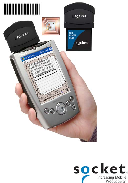
CF RFID Reader-Scan Card™
Series 6
Dual-Function RFID Reader and
Bar Code Scanner for Pocket PCs
User’s Guide

9/2005 Document # 6410-00266 A
Copyright Notice
Copyright © 2005 Socket Communications, Inc. All rights reserved.
Socket, the Socket logo and Mobility Friendly are registered trademarks of
Socket Communications, Inc. CF RFID Reader-Scan Card, RFID Demo,
SocketScan, and SocketScan Trigger are registered trademarks or
trademarks of Socket Communications, Inc. All other brand and product
names are trademarks of their respective holders.
Reproduction of the contents of this manual without the permission of
Socket Communications is expressly prohibited. Please be aware that the
products described in this manual may change without notice.
Feel free to contact SOCKET COMMUNICATIONS at:
Socket Communications, Inc.
37400 Central Court
Newark, CA 94560
Other than the above, Socket Communications can assume no responsibility
for anything resulting from the application of information contained in this
manual.
Please refrain from any applications of the Socket CF RFID Reader Card
that are not described in this manual. Please refrain from disassembling the
CF RFID Reader Card. Disassembly of this device will void the product
warranty.
You can track new product releases, software updates and technical
bulletins by visiting Socket’s web page at: www.socketcom.com.
Table of Contents
COPYRIGHT NOTICE 2
1 | INTRODUCTION 5
About the Software 5
System Requirements 6
Package Contents 6
Product Registration 6
Resellers and Integrators 6
Vertical Solutions 6
2 | SETUP FOR WINDOWS MOBILE 7
STEP 1: Uninstall Other Scanning Software 8
STEP 2: Install the Software 9
STEP 3: Insert the CF RFID Reader-Scan Card 10
STEP 4: Assign Trigger Button(s) 11
STEP 6: Read Data into a Windows Program 13
OPTIONAL: Configure RFID 19
OPTIONAL: Configure Prefix/Suffixes 20
OPTIONAL: Configure Sounds 21
OPTIONAL: Configure Bar Code Symbologies 22
OPTIONAL: Use SocketScan Trigger 23
OPTIONAL: View Version Information 25
3 | RFID DEMO 26
Read an RFID Tag 27
Enable Inventory and Loop Modes 29
Select Tag Type 30
ADVANCED: Write to Tag 31
APPENDICES
A | PRODUCT SPECIFICATIONS 34
B | HF RFID STANDARDS & TAG DESCRIPTIONS 35
C | BAR CODE LABEL SPECIFICATIONS 44
D | CLASS 1 VS. CLASS 2 LASER SCANNERS 45
E | ENABLING OR DISABLING SYMBOLOGIES 48
F | LASER DECODE ZONE 50
G | TROUBLESHOOTING 52
3
1 | Introduction
As RFID begins to supplement bar codes in many
applications, both technologies will co-exist for
many years. Now you can add high frequency RFID
read/write and laser bar code scanning capabilities
to your Pocket PC-based data collection application
with the Socket CF RFID Reader-Scan Card. This
dual-function device reads and writes to all ISO
15693 and many proprietary 13.56 MHz RFID tags
and also scans all common linear bar codes.
The CF RFID Reader-Scan Card is sleekly designed
with no cables or batteries – it draws minimal power
from the Pocket PC. Plus, the card is designed to
withstand repeated three-foot drops to concrete –
even when inserted into the Pocket PC.
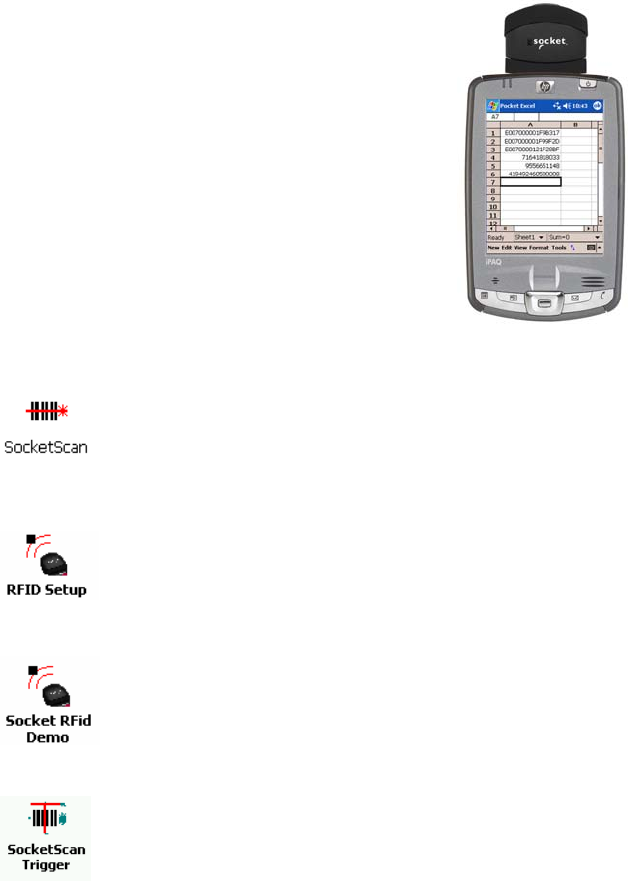
About the Software
SocketScan™ enters the RFID tag ID or bar coded data
directly into any open Windows program, as if the data were
manually typed. You can configure Prefix/Suffixes,
enable/disable bar code symbologies, and assign a beep tone
to signify good data reads.
The RFID Setup utility allows you configure what kinds of
data are returned after reading RFID tags, including tag ID,
tag memory, tag types, tag type prefix, etc. You can also
enter a string used to indicate read errors and enable/disable
inventory mode.
Socket RFID Demo allows you to read memory blocks of
selected RFID tags in range in either Inventory Mode or a
continuous Loop Mode. For advanced users, there is also the
capability to write data to the RFID memory.
SocketScan Trigger places a software trigger on your screen
that you can tap to trigger the reader or scanner. Installation
is optional.
CHAPTER 2: SETUP FOR WINDOWS MOBILE 5
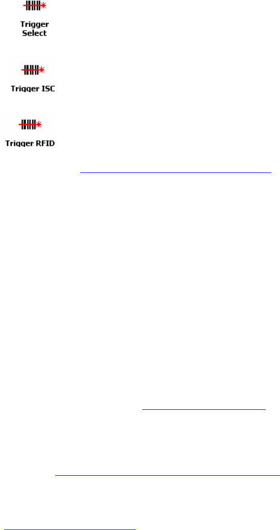
The Trigger Select program allows you to press a button to
quickly switch between the RFID and laser scanning modes
of the RFID Reader-Scan Card.
The Trigger ISC program allows you to assign a button on
your Pocket PC exclusively for triggering the bar code laser
scanner.
The Trigger RFID program allows you to assign a button on
your Pocket PC exclusively for triggering the RFID reader.
Software updates: www.socketcom.com/support/support_bar.asp
System Requirements
Your device should meet these minimum requirements:
• Pocket PC running Windows Mobile 2003/2003SE
• Available CompactFlash or PC Card slot
(Operation in a PC Card slot requires a PC Card adapter, available
separately, SKU# AC4000-978.)
Package Contents
The CF RFID Reader-Scan Card package includes the following:
• Socket CF RFID Reader-Scan Card
• SocketScan Installation CD
• Booklet with copyright and warranty information
Product Registration
Socket highly recommends that all customers register their products.
Registered users receive priority for technical support, product updates, and
special offers. Register online at: www.socketcom.com/prodreg. Product
registration is not required to ensure your warranty rights.
Resellers and Integrators
For information about Socket’s Strategic Vertical Integrator (SVI) Program,
please visit: www.socketcom.com/solutions/default.asp?Type=SVI
Vertical Solutions
For information about third party vertical application solutions, please visit:
www.socketcom.com/solutions/
6
2 | Setup for Windows Mobile
This chapter shows how to install, configure, and use
the CF RFID Reader-Scan Card on a Pocket PC
running any of the following versions of Windows
Mobile:
• Windows Mobile 2003
• Windows Mobile 2003SE (Second Edition)
The product includes support for square screens and
landscape mode for Windows Mobile.
Setup Summary
STEP 1: Uninstall other bar code scanning software.
STEP 2: Install the software.
STEP 3: Insert the CF RFID Reader-Scan Card.
STEP 4: Start SocketScan.
STEP 5: Assign a trigger button.
STEP 6: Read tag IDs into a Windows program.
OPTIONAL:
• Configure RFID
• Configure prefix/suffixes.
• Configure sounds to confirm a successful read.
• Configure bar code symbologies.
• Use SocketScan Trigger.
• View version information.
CHAPTER 2: SETUP FOR WINDOWS MOBILE 7

STEP 1: Uninstall Other Scanning Software
Delete any bar code scanning software you may already have installed on
your Pocket PC. You can either uninstall the software directly from your
Pocket PC, or indirectly via ActiveSync.
OPTION 1: Uninstall Directly from the Pocket PC
1. Make sure the bar code scanning software is closed, and remove the CF
RFID Reader Card from your Pocket PC.
2. Tap Start | Settings. Tap on the System tab or Control Panel.
3. Tap on the Remove Programs icon.
4. Select the bar code scanning software, then tap Remove.
5. Tap Yes to confirm removal of the program.
OPTION 2: Uninstall via ActiveSync
1. Make sure the bar code scanning software is closed, and remove the CF
RFID Reader Card from your Pocket PC.
2. Use ActiveSync and a serial/Ethernet/USB cable or cradle to make an
active connection between your Pocket PC and a host PC.
3. On the host PC, open Microsoft ActiveSync.
4. Click Tools | Add/Remove Programs.
5. Select the bar code scanning software and click Remove.
6. In the confirmation screen, click OK.
7. The next dialog will ask if you want to remove the software from your
host PC as well.
• Click NO to keep a copy of the software on the host PC that can later
be re-installed onto a Pocket PC.
• Click YES to remove the software from the host PC.
8
STEP 2: Install the Software
Follow these instructions to install SocketScan into your Pocket PC.
Afterwards, you may choose to repeat the same process to install the RFID
Demo and/or Floating Trigger software, if desired.
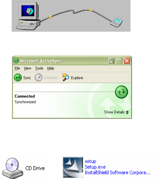
1. Use ActiveSync and a serial/Ethernet/USB cable or cradle to make an
active connection between the Pocket PC and a host PC.
ActiveSync should report that you have Connected, and the ActiveSync
logo should turn green.
Pocket_PC
2. Insert the installation CD into your host PC.
3. Use My Computer or Windows Explorer to access your CD-ROM drive.
In the CD, click on SETUP.EXE.
CHAPTER 2: SETUP FOR WINDOWS MOBILE 9
4. SocketScan will begin to automatically install on your Pocket PC.
Follow the screens on your host PC and Pocket PC.
5. If your Pocket PC warns that the software comes from an unknown
publisher, tap Yes to continue installation.
6. When software installation is complete, remove the Pocket PC from the
cradle. Soft reset the Pocket PC by pressing the reset button.
Note: After software installation, several new icons will appear in the
Programs screen.
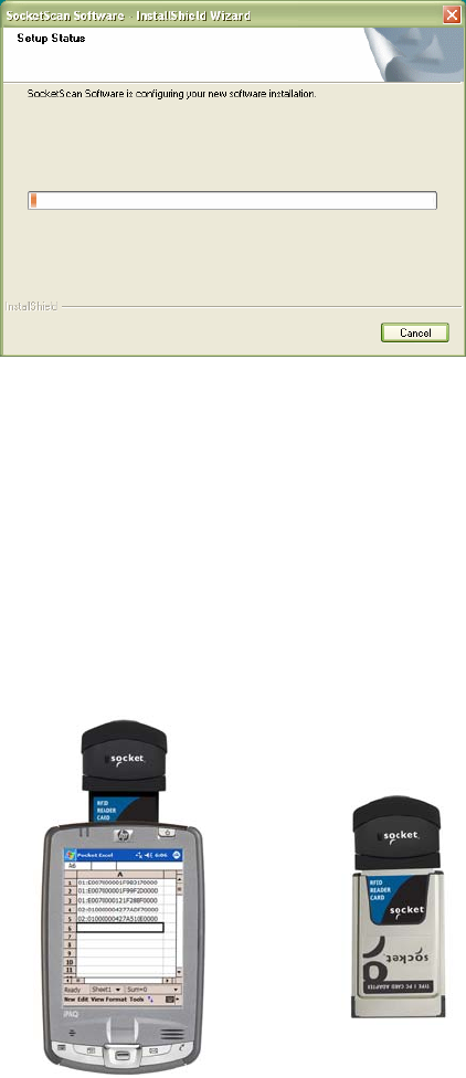
STEP 3: Insert the CF RFID Reader-Scan Card
Insert into a PC
Card adapter, then
plug the combined
unit into a PC Card
s
lot.
Plug directly into
a CompactFlash
card slot. OR
10
STEP 4: Assign Trigger Button(s)
You must set up a mechanism for triggering the CF RFID Reader-Scan Card.
Hardware button(s) are the best triggering method from a Pocket PC. To
make the dual functionality of the CF RFID Reader-Scan Card easy to use,
SocketScan allows you to configure up to four buttons for launching
SocketScan and/or triggering the RFID reader or bar code scanner. Please
refer to the chart below to determine which SocketScan functions you would
like to assign to buttons on your Pocket PC.
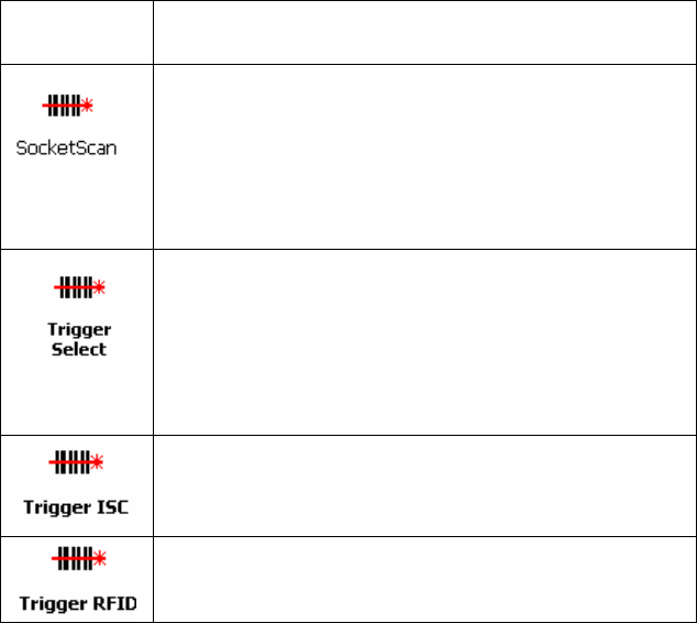
Program What happens when you press a button assigned
to this program?
SocketScan will launch. If SocketScan is already running,
pressing this button will trigger either the RFID reader or
laser scanner, depending on which mode the card is in. If
you assign only one hardware button for use with the CF
RFID Reader-Scan Card, this is the program that should be
assigned. If you do not assign a button to this, you will have
to manually start SocketScan by tapping Start | Programs |
SocketScan.
Your Pocket PC will switch from RFID mode to bar code
scanning mode, or vice versa. This is designed to be used
in conjunction with a trigger button assigned to
SocketScan. You can also use Trigger Select to toggle to
other Socket bar code scanners that use a software trigger.
The laser bar code scanner will be triggered. SocketScan
must be running.
The RFID reader will be triggered. SocketScan must be
running.
Note:
• If it is inconvenient or impossible for you to assign a hardware button
on your Pocket PC, you can install SocketScan Trigger from the
installation CD, which allows you to tap on the icon to trigger
SocketScan and the RFID reader/bar code scanner.
• Refer to your Pocket PC manual for specific instructions on assigning
buttons.
CHAPTER 2: SETUP FOR WINDOWS MOBILE 11
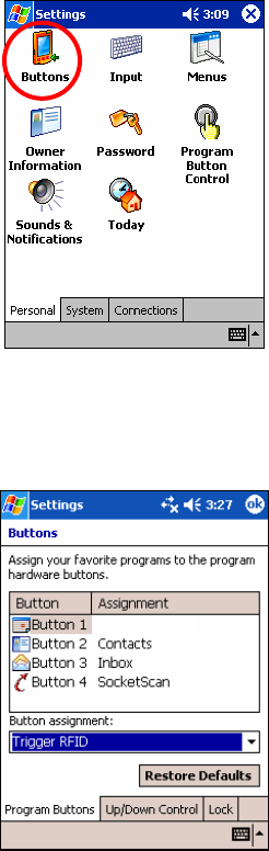
1. Tap Start | Settings | Personal | Buttons.
2. In the Button list, tap to highlight a button you would like to assign a
new program to. In the drop-down menu, select the program. If desired,
repeat to assign additional trigger buttons. When done, tap ok.
Trigger Select
Note: For maximum ergonomic placement, choose a button located
directly beneath your thumb or forefinger when you hold the Pocket PC.
The Voice Record button is a good choice for many Pocket PCs, if
available.
12
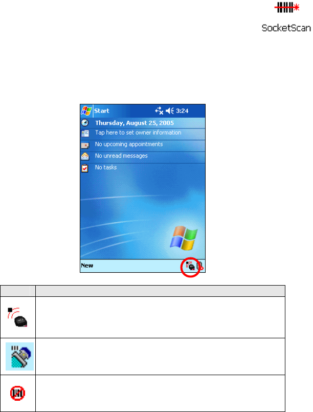
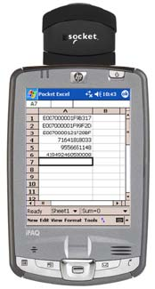
STEP 5: Read Data into a Windows Program
1. Start SocketScan. If you assigned a hardware button to
SocketScan, you can press the button to quickly launch
the program. Otherwise, tap Start | Programs |
SocketScan.
2. Whenever SocketScan is running, any of three icons may appear at the
bottom of the Today screen. Make sure an icon appears indicating that
the SocketScan detects the reader-scan card, either in RFID or scanning
mode.
Icon Meaning.
Card detected, RFID mode. SocketScan detects the
reader-scan card and is ready to read RFID tags.
Card detected, scanning mode. SocketScan detects the
reader-scan card and is ready to read bar codes.
No RFID Reader Card detected. The reader card is either
missing or improperly inserted.
Note:
• If the card is inserted, but SocketScan does not detect it, push the
card gently but firmly all the way into the slot.
• By default, the RFID Reader Card will return the tag ID. The RFID
Setup utility can be used so that the RFID Reader Card returns only
the tag data, or the tag ID plus the tag data.
CHAPTER 2: SETUP FOR WINDOWS MOBILE 13
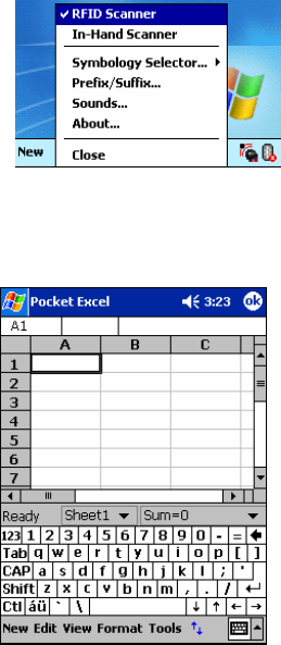
3. If you did not assign buttons to Trigger ISC or Trigger RFID, make sure
the CF RFID Reader-Scan Card is in the correct mode for the function
you wish to use. The SocketScan icon at the bottom of the Today screen
indicates your current mode.
To switch modes, do either of the following:
• If you assigned a button to Trigger Select, press the button.
• Tap on the SocketScan icon. In the pop-up menu, tap to select the
card mode you want.
4. Start the Windows application that you want to receive the data (e.g.,
Excel, Notepad, etc.). Make sure a document or spreadsheet is open.
Place the cursor where you want to enter data.
Note: If reading RFID tags into Excel, you may want to increase the cell
width to fit the entire length of a tag ID, which may have more than 20
characters.
5. Hold the Pocket PC so the CF RFID Reader-Scan Card is in the correct
reading/scanning position (see next page) and press the trigger button.
Please note that the correct positions for RFID reading and
bar code scanning are very different!
14
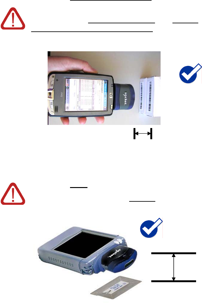
CORRECT BAR CODE SCANNING POSITION:
Hold the RFID Reader-Scan Card so that the lens
is angled about 45° to the bar code and at least
2.0 inches away from the bar code. The red laser
line should cover the entire width of the bar code.
Note: The proper scanning distance and angle vary depending
on the size, type and quality of the bar code, and the quality of
the printing material.
CORRECT RFID POSITION:
Hold the RFID Reader Card parallel to and directly
above the tag, at most 2.0 inches above the tag.
2.0 inches MIN.
Parallel,
2.0 inches MAX.
Note: The LED will turn amber to indicate that the RFID Reader Card
is reading tag IDs. It does not indicate a successful read, nor does it
indicate bar code scanning.
16
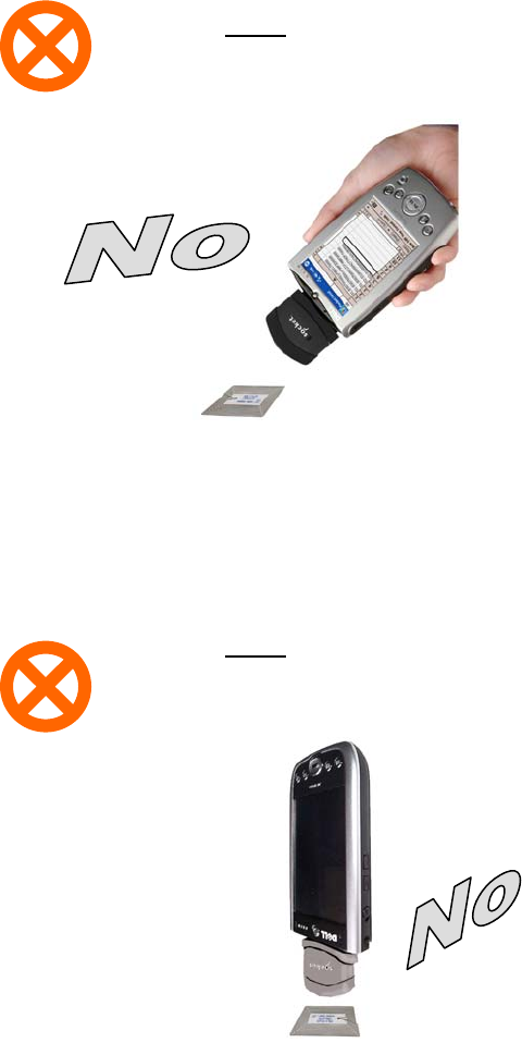
WRONG RFID POSITION:
DO NOT direct the RFID Reader-Scan Card at
an angle towards the tag.
WRONG RFID POSITION:
DO NOT hold the RFID Reader-ScanCard
perpendicular to the tag.
CHAPTER 2: SETUP FOR WINDOWS MOBILE 17
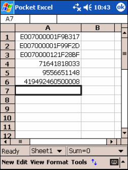
6. When data is read, a beep should sound indicating a good read, and data
should appear in your application. For example, in an Excel spreadsheet,
data should appear in the cell you highlighted. The next cell should now
be highlighted, ready for the next scan/read.
If the CF RFID Reader-Scan Card fails to read data within a few
seconds, you must try again.
Note:
• If your Pocket PC enters sleep mode when SocketScan is running,
press the ON button to restart SocketScan and initialize the reader.
• By default, the RFID Reader Card will return the tag ID. The RFID
Setup utility can be used so that the RFID Reader Card returns only
the tag data, or the tag ID plus the tag data. (See the next page for
instructions.)
18
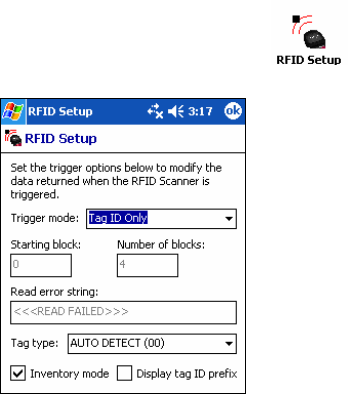
OPTIONAL: Configure RFID
This utility allows you to configure what kinds of data are returned after
reading RFID tags.
Note: These settings are only used with the SocketScan keyboard wedge programs
and Scan Demo.
1. Tap Start | Settings | System tab | RFID Setup.
2. Enter your desired settings, then tap ok.
Trigger mode:
• Tag ID only: Select to read only the tag ID.
• Read Data Only: Select to read only data from the tag memory.
• Tag ID & Read Data: Select to read both the tag ID and tag memory.
Starting block: If you selected a Read Data option in the drop-down
menu, enter the number of the first block you want to begin reading.
Number of blocks: If you selected a Read Data option in the drop-down
menu, enter the number of blocks you want to read.
Read error string: Enter what string you want your application to display in
case the CF RFID Reader-Scan Card has problems reading the tag data.
Tag type: Select the type of RFID tag you would like to read. The Auto
Detect setting enables all tag types to be read.
Note: Selecting a specific tag may result in a longer read range and faster read.
Inventory mode: Check to enable inventory mode. The CF RFID Reader-Scan Card
will read all of the tags present in an RFID field, if supported by the tag type.
Display tag ID prefix: Check to display the RFID tag ID prefix with each
tag ID. The prefix indicates the tag type.
CHAPTER 2: SETUP FOR WINDOWS MOBILE 19
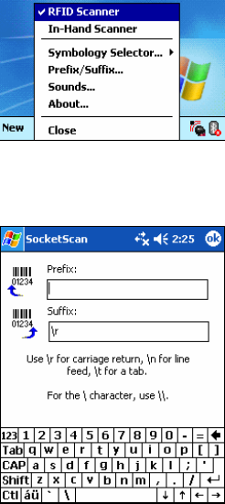
OPTIONAL: Configure Prefix/Suffixes
The SocketScan applet lets you specify prefix and/or suffix characters to be
added automatically to the data you read. This helps to further eliminate
manual data entry.
1. Tap on the SocketScan icon. In the pop-up menu, tap Prefix/Suffix.
Note: You can configure prefix/suffixes whether or not the CF RFID
Reader-Scan Card is inserted into your Pocket PC.
2. In the pop-up menu, select Prefix/Suffix...
3. In the screen that appears, enter the characters you want to be appended
to each tag read (128 character maximum). Tap ok.
Note: Only printable
ASCII characters can
be used as prefixes or
suffixes.
Note:
• The default suffix is a carriage return.
• If in the RFID Setup utility you selected Tag ID & Read Data, the
prefix/suffix is added to both the tag ID and the read data fields.
20
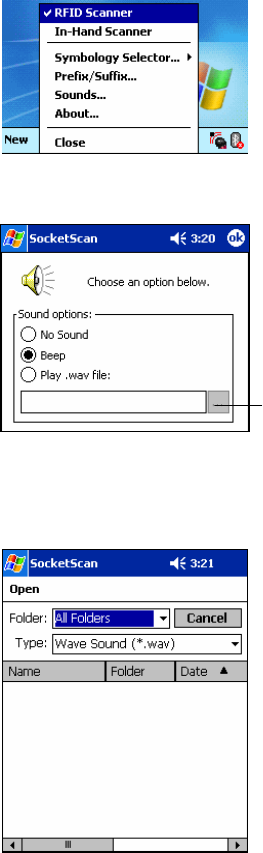
OPTIONAL: Configure Sounds
The SocketScan Sounds applet lets you choose any WAV sound file to be
played to indicate a successful read.
1. Tap on the SocketScan icon at the bottom of the Today screen.
2. In the pop-up menu, select Sounds...
3. In the screen that appears, select a sound for indicating successful reads.
Tap ok.
Browse box
To you want to play a .WAV file, after selecting Play .wav file, you can
search through files by tapping the browse box. In the Open screen, tap
on the file you want:
Note: You can only select
a WAV file from the My
Documents folder. If
needed, copy the file you
need to this folder.
CHAPTER 2: SETUP FOR WINDOWS MOBILE 21
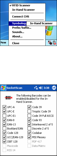
OPTIONAL: Configure Bar Code Symbologies
SocketScan provides an applet that makes it easy to modify which bar code
symbologies you want the scanner to recognize and attempt to decode. By
default, the scanner is set to recognize several of the most common
symbologies.
1. Tap on the SocketScan icon at the bottom of the Today screen.
2. In the pop-up menu, tap Symbology Selector. If SocketScan is currently
configured for more than one scanner, then tap In-Hand Scanner in the
submenu that appears.
Note: The Connect CHS option will only appear if you have enabled
SocketScan for the Cordless Hand Scanner in the Socket CHS
configuration utility.
3. In the screen that appears, use the checkboxes to enable/disable
symbologies. Tap ok.
Note:
• Symbologies not supported by the CF RFID Reader-Scan Card will be
grayed out.
• Enabling all possible symbologies will make the decode process
slightly longer.
22
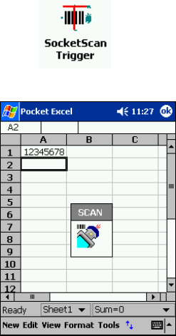
OPTIONAL: Use SocketScan Trigger
If you find it inconvenient or impossible to assign or use a hardware button
to trigger the reader, you can install this virtual trigger button that “floats”
on top of the active application.
1. Make sure to do all of the following before using SocketScan Trigger:
• Install SocketScan Trigger from the installation CD. The software
must be installed separately from SocketScan.
• Start SocketScan. Tap Start | Programs | SocketScan.
• Insert the CF RFID Reader-Scan Card into your Pocket PC.
• Open the application that you want to read the tag ID into.
2. Start SocketScan Trigger. Tap Start | Programs | SocketScan Trigger.
3. The floating trigger button will appear on your screen on top of the
active application.
Drag from the title bar to move the trigger button to a convenient place
on the screen.
Tap the trigger button to activate the RFID Reader-Scan Card.
(The trigger will activate the selected function (either the RFID reader
or the laser scanner), as indicated by the SocketScan icon at the bottom
of the Today screen.)
CHAPTER 2: SETUP FOR WINDOWS MOBILE 23
4. A SocketScan Trigger icon will also appear in the menu bar of the
Today screen. Tap on this icon to reveal a pop-up menu with the
following options:
• Tap Scan Now to activate the scanner as if you had tapped the
trigger button.
• Tap Remove Floating Trigger to remove the trigger button from the
screen but keep the icon handy on the task bar. To restore the
trigger button, tap on the menu bar icon. In the pop-up menu, tap
Launch Floating Trigger.
• Tap About to view SocketScan Trigger version information.
• Tap Close SocketScan Trigger to close the application completely.
From this state, the SocketScan trigger can only be launched from
the Programs page.
24
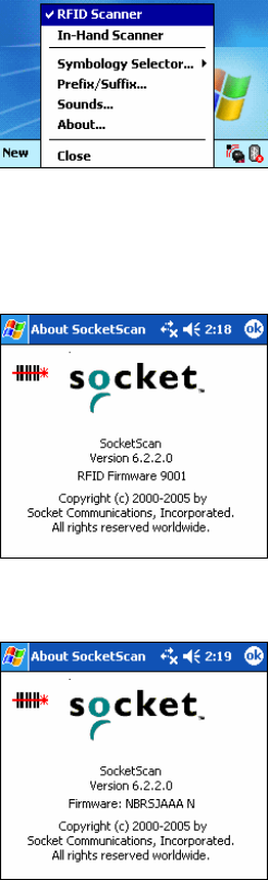
OPTIONAL: View Version Information
SocketScan includes an About screen which displays the SocketScan
version, as well as the firmware/scan engine version for the selected device.
1. In the Today screen, check the SocketScan icon at the bottom of the
screen to verify that the correct device is selected. If required, select the
correct device by tapping on the icon and in the pop-up menu, selecting
the device you want.
2. Tap on the SocketScan icon at the bottom of the screen. In the pop-up
menu, tap About. The screen reports the SocketScan version.
If the RFID Reader is currently selected, the RFID firmware version
will also appear.
If the bar code scanner is currently selected, the scanning
engine/firmware version will appear.
Note: If you need technical support for your device, please include these
firmware versions with your request.
CHAPTER 2: SETUP FOR WINDOWS MOBILE 25
3 | RFID Demo
This chapter shows how to use the Socket RFID Demo
application with the Socket CF RFID Reader-Scan Card to
perform the following:
• Read an RFID Tag.
• Enable Loop Mode.
• Select Tag Type.
• Advanced – Write to Tag.
Before you begin using the Socket RFID Demo application, make sure you
have done the following:
• Installed the RFID Demo application onto your Pocket PC, following
the same software installation procedure described in Chapter 2.
• Inserted the CF RFID Reader-Scan Card into your Pocket PC.
• When you use this application, you should only trigger the RFID Reader
Card by tapping on the Select Tags or Read Tag button on the RFID
Demo screen.
26
Read an RFID Tag
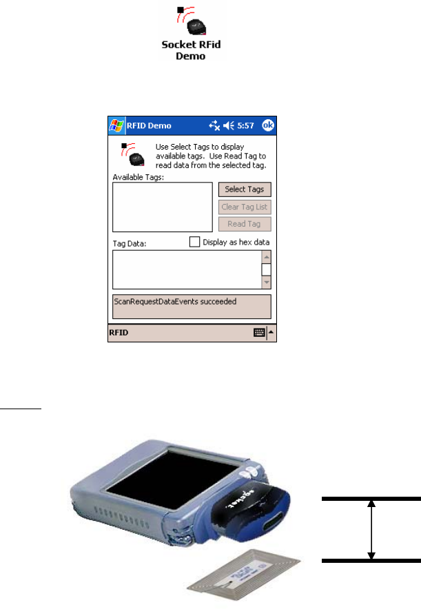
1. Start RFID Demo. Tap Start | Programs | RFID Demo.
2. The main screen of RFID Demo will appear with blank fields.
3. Hold the Pocket PC in the correct position to read an RFID tag, as
described in Chapter 2. Hold the Pocket PC so the RFID Reader Card is
parallel to and directly above the tag, at most 2.0 inches above the tag.
Parallel,
2.0 inches MAX.
4. Tap Select Tags.
CHAPTER 3: RFID DEMO 27
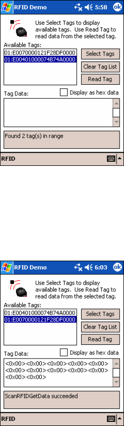
5. Tag ID(s) should appear in the Available Tags field. Additionally, the
bottom of the screen will report the number of RFID tags found in
range.
6. In the Available Tags field, tap to highlight the RFID tag you wish to
read, then tap Read Tag.
7. After the Socket RFID Reader Card reads the tag, Tag Data will appear.
If desired, check Display as hex data to view the data in hexadecimal
format.
28
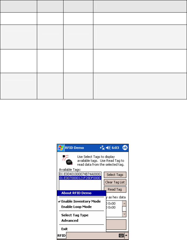
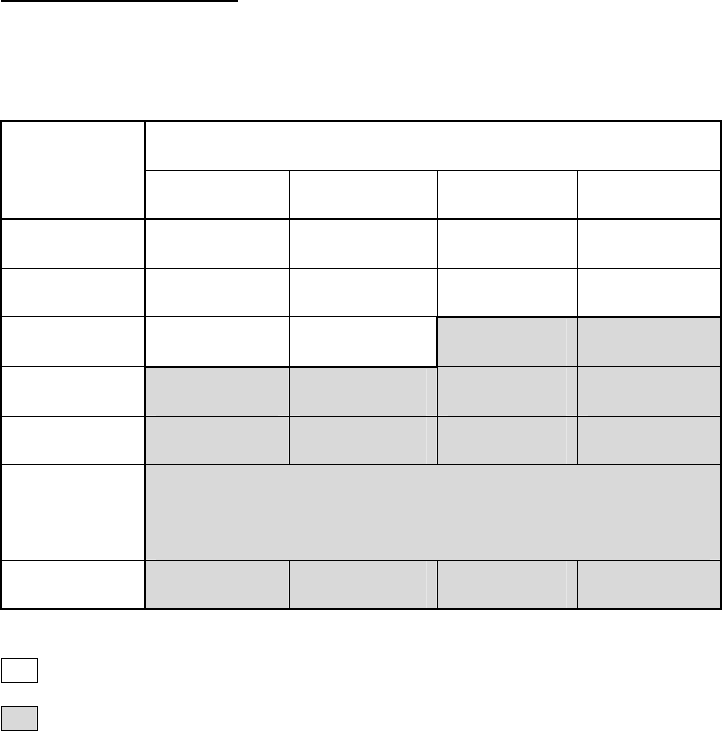
Enable Inventory and Loop Modes
The Socket RFID Reader Card has four types of reading modes that result
from different combinations of inventory mode and loop mode. The chart
below describes the results of enabling or disabling the modes.
Tag Select
Mode Loop
Mode Inventory
Mode Description
One tag Disabled Disabled Selects the first tag in RF field
One tag
continuously Enabled Disabled Selects the first tag continuously (the
same tag ID will be returned as long as
the tag remains in the RF field.
All tags
present Disabled Enabled Inventory mode: returns the tag IDs of
all tags in the RF field and then reports
when there are no more tags.
All tags
continuously Enabled Enabled
Returns the tag IDs of all tags in the RF
field. It does not repeat a tag ID unless
the tag goes out and then re-enters the
RF field.
Note: Not all tag types are readable when Inventory Mode is enabled.
1. In the main screen of RFID Demo, tap RFID at the bottom of the screen.
In the pop-up menu, select adjust the Inventory Mode and/or Loop
Mode settings as desired.
2. After selecting the desired settings, tap Select Tags. The RFID Reader
Card will begin searching for tags in range, according to the settings you
enabled.
CHAPTER 3: RFID DEMO 29
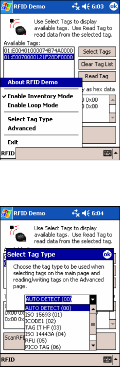
Select Tag Type
1. In the main screen of Socket RFID Demo, tap RFID at the bottom of the
screen. In the pop-up menu, tap Select Tag Type.
2. In the Select Tag Type dialog box, use the drop-down menu to select the
tag type. Tap ok.
Note:
• Tag selection response time is longer with Auto Detect than for specific
tag types. If Auto Detect is not selected, only the type of tags selected
can be read or written to.
• Auto Detect will search for tag types 01 to 04. Pico Tag (06) must be
selected in order to read tag ID.
30
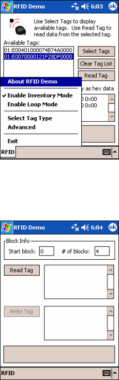
ADVANCED: Write to Tag
1. In the main screen of Socket RFID Demo, tap RFID at the bottom of the
screen. In the pop-up menu, tap Advanced.
2. Use the next screen to read and write data in specific blocks of an RFID
tag. Enter the number of the starting block and number of blocks you
would like to read.
3. Hold the Pocket PC in the correct position to read RFID tags — parallel
to the tag and directly above it, at most 2.0 inches above. Tap Read Tag.
CHAPTER 3: RFID DEMO 31
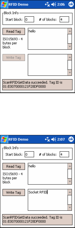
4. RFID Demo will report any data saved to the RFID tag, as well as the
type of tag and number of bytes per block. The bottom of the screen will
report the read status and tag ID.
5. To write data to the tag, enter text into the bottom field. The type and
amount of text that can be written varies depending on your tag type.
After entering text, hold the Pocket PC in the correct reading/writing
position and tap Write Tag.
Note:
• The number of characters in the Write Tag field must match the
number of bytes per block multiplied by the number of blocks, or an
error will occur.
• See Appendix B to find out the type and amount of text that can be
written to your tag.
• The most common cause of write failures is either an incorrect “start
block” or number of blocks.
32
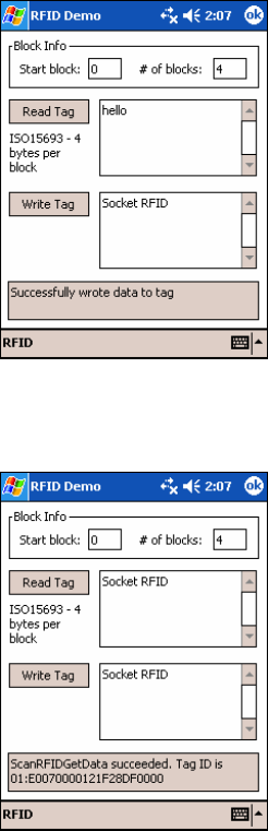
6. After writing data to the tag, the bottom of the screen will report the
write status.
7. To verify that the data was written successfully to the tag, hold the
Pocket PC in the correct reading/writing position, and tap Read Tag.
8. To close the advanced screen, tap ok.
CHAPTER 3: RFID DEMO 33
34
Appendix A
Product Specifications
Physical Characteristics
CompactFlash Card Size: 1.43 x 1.68 x 0.20 inches (36 x 42.7 x 5.0 mm)
Weight: 1.6 oz. (45 g)
Scanner Head Size: 1.76 x 1.93 x 0.82 inches (45 x 49 x 21 mm)
Power Consumption (3.3 V):
Idle: 11 mA
RFID Reading/Writing: 52 mA
Bar Code Scanning: 72 mA
Also operates at 5 V
Environmental:
Operating Temperature: 10 to +50°C (-4 to +122°F)
Storage Temperature: -40 to +70°C (-40 to +158°F)
Humidity: 5-95% RH non-condensing
Compatibility: Windows COM port
Operating System Support: Windows CE.NET v4.2 (Windows Mobile)
Certification: FCC: Part 15, Class B, CE: EN55024:1998, C-TICK: s.182
RFID Characteristics:
Frequency: 13.56 MHz (HF)
Maximum Read Range: 2.0 inches, depending on tag antenna size
HF RFID Tags Supported
ISO15693: ICode SL2, LRI512, my-d, Tag-It HF-I
Proprietary: ICode 1, PicoTag (tag ID only), Tag-It HF, GemWave (tag ID only)
Scanner Characteristics: Laser Classes Available:
Version 6M: Laser Class 1 Version 6P: Laser Class 2
APPENDIX B: HF RFID STANDARDS AND TAG DESCRIPTIONS 35
Appendix B
HF RFID Standards and Tag Descriptions
ISO15693
The ISO/IEC 15693 standard was developed for “Contactless Vicinity Cards”. Adopted in 1998, ISO15693
has significantly enabled global acceptance of 13.56MHz RFID technology. Based on contributions by
Texas Instruments and Philips, ISO/IEC 15693 is largely a superset of the features and specifications of the
Tag-it HF and I·Code1 products, respectively.
• ISO15693-1: Defines the physical characteristics of a credit card transponder.
• ISO15693-2: Specifies the 13.56MHz air interface and modulation methods that accommodate
regulatory bodies worldwide.
• ISO15693-3: Specifies the command protocol and anti-collision method for data exchange between
tags and readers.
The ISO15693 “standard” permits tags to be manufactured that support optional and custom commands,
and that have custom memory structures, sizes and architectures. The SkyeRead family of RFID readers
fully supports all four (4) IC manufacturers that offer ISO/IEC 15693 compatible tags.
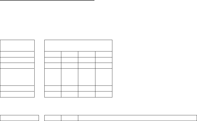
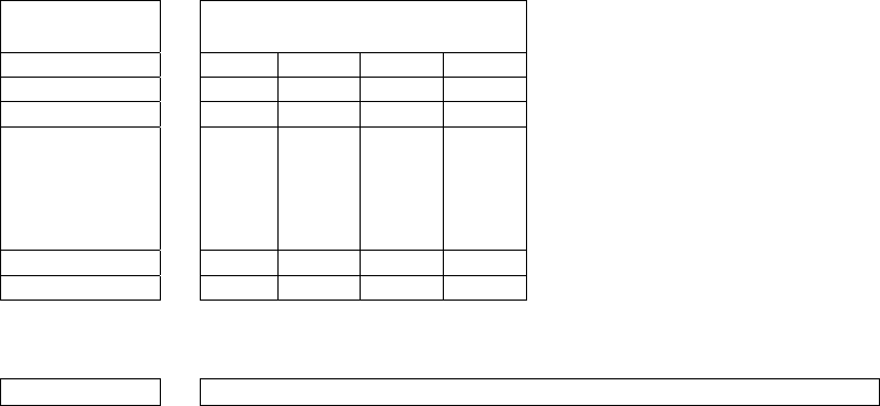
Tag-It HF-I ISO15693 (Texas Instruments)
The complete Tag-It HF-I specification can be found in the Texas Instruments publication titled “Tag-It
HF-I Transponder Inlays Reference Guide”.
Figure 1 - Memory Structure of the Tag-It HF-I
2K bits (256 bytes) of user memory is available for read/write.
Block # 32 bits
(4 bytes per block)
0 (0x00)
1 (0x01)
2 (0x02)
.
.
.
.
.
.
.
.
.
.
.
.
.
.
.
62 (0x3E)
63 (0x3F)
The user can permanently lock
any block.
Once a block is locked it can
not be unlocked.
A 64-bit ID (factory programmed) uniquely identifies each Tag-It HF-I chip.
TID 0xE0 0x07 Unique Tag ID - 48 bits (6 bytes)
36
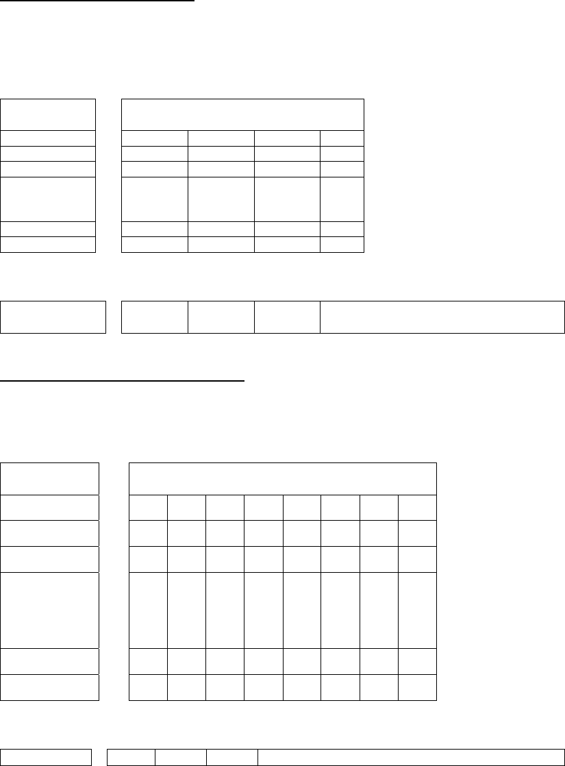
I·Code SLI ISO15693 (Philips)
The complete I·Code SLI specification can be found in the Philips publication titled “I·Code SLI Smart
Label IC SL2 ICS20 Functional Specification”.
Figure 1 - Memory Structure of the I·Code SLI (version SL2 ICS20)
896 bits (112 bytes) of user memory is available for read/write.
Block # 32 bits
(4 bytes per block)
0 (0x00)
1 (0x01)
2 (0x02)
.
.
.
.
.
.
.
.
.
.
.
.
.
.
.
26 (0x1A)
27 (0x1B)
The user can permanently lock
any block.
Once a block is locked it can not
be unlocked.
A 64-bit ID (factory programmed) uniquely identifies each I·Code SLI chip (SL2 ICS20).
TID 0xE0 0x04 0x01 Unique Tag ID 40 bits (5
bytes)
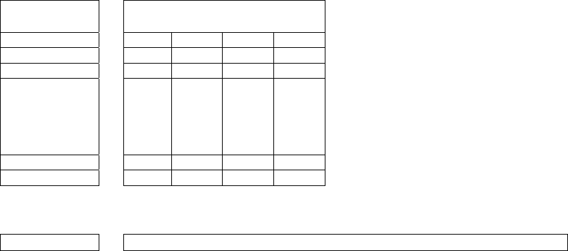
my-d SRF55VxxP ISO15693 (Infineon)
The complete my-d SRF55VxxP specification can be obtained from Infineon.
Figure 2 - Memory Structure of the my-d SRF55V02P
29 blocks of 8 bytes = 232 bytes (1856 bits) of user memory is available for read/write.
Block # 64 bits
(8 bytes per block)
3 (0x03)
4 (0x04)
5 (0x05)
.
.
.
.
.
.
.
.
.
.
.
.
.
.
.
.
.
.
.
.
.
.
.
.
.
.
.
30 (0x1E)
31 (0x1F)
The user can
permanently lock
any block
Once a block is
locked it can not be
unlocked.
A 64-bit ID (factory programmed) uniquely identifies each my-d SRF55V02P chip.
TID 0x60 0x05 0x02 Unique Tag ID - 40 bits (5 bytes)
APPENDIX B: HF RFID STANDARDS AND TAG DESCRIPTIONS 37
Figure 4 - Memory Structure of the my-d SRF55V10P
125 blocks of 8 bytes = 1000 bytes (8000 bits) of user memory is available for read/write.
Block # 64 bits
(8 bytes per block)
3 (0x03)
4 (0x04)
5 (0x05)
.
.
.
.
.
.
.
.
.
.
.
.
.
.
.
.
.
.
.
.
.
.
.
.
.
.
.
126 (0x7E)
127 (0x7F)
The user can
permanently lock
any block
Once a block is
locked it can not be
unlocked.
A 64-bit ID (factory programmed) uniquely identifies each my-d SRF55V10P chip.
TID 0x60 0x05 0x00 Unique Tag ID - 40 bits (5 bytes)
LRI512 ISO15693 (ST Microelectronics)
The complete LRI512 specification can be found in ST Microelectronics’ publication titled “LRI512
Memory TAG IC 512 bit High Endurance EEPROM 13.56MHz, ISO 15693 Standard Compliant with
E.A.S.”.
Figure 5 - Memory Structure of the STM LRI512
512 bits (64 bytes) of user memory is available for read/write.
Block # 32 bits
(4 bytes per block)
3 (0x03)
4 (0x04)
5 (0x05)
.
.
.
.
.
.
.
.
.
.
.
.
.
.
.
14 (0x0E)
15 (0x0F)
The user can permanently lock any
block.
Once a block is locked it can not be
unlocked.
A 64-bit ID (factory programmed) uniquely identifies each STM LRI512 chip.
TID 0xE0 0x02 Unique Tag ID 48 bits (6 bytes)
38
Tag-it HF
The first 13.56MHz RFID IC that Texas Instruments developed was the Tag-it HF. Still in high volume
production, Tag-it HF is widely used in applications globally and has an existing installed base of millions
of tags. The Tag-it HF uses a protocol air interface that is proprietary to Texas Instruments.
By contrast, the Tag-it HF-I was released by Texas Instruments in 2001 is compatible with ISO/IEC 15693
parts -2 and -3. The host application developer should be aware of the distinction between the Tag-it HF
and the Tag-it HF-I.
Figure 6 - Memory Structure of the Tag-it HF
256 bits (32 bytes) of user memory is available for read/write.
Block # 32 bits
(4 bytes per block)
0 (0x00)
1 (0x01)
2 (0x02)
.
.
.
.
.
.
.
.
.
.
.
.
.
.
.
6 (0x06)
7 (0x07)
The user can permanently lock any
block.
Once a block is locked it can not be
unlocked.
A 32-bit ID (factory programmed) uniquely identifies each Tag-it HF chip.
TID Unique Tag ID 32 bits (4 bytes)
The complete Tag-it HF specification can be obtained from Texas Instruments.
APPENDIX B: HF RFID STANDARDS AND TAG DESCRIPTIONS 39
I·Code1
The first long range 13.56MHz RFID IC that Philips released was the I·Code1 (SL1). Still in high volume
production, I·Code1 (SL1) is still widely used in applications globally and has an existing installed base of
millions of tags. The I·Code1 (SL1) uses a protocol and air interface that is proprietary to Philips.
By contrast, the I·Code SLI (SL2), released by Philips in 2002, is fully compatible with ISO/IEC 15693
parts -2 and -3. The host application developer should be explicitly aware of the distinction between the
I·Code1 (SL1) and the I·Code SLI (SL2).
Figure 7 - Memory Structure of the I·Code1 (version SL1 ICS30 01)
512 bits (64 bytes) of user memory is available for read/write.
Block # 32 bits
(4 bytes per block)
3 (0x03)
4 (0x04)
5 (0x05)
.
.
.
.
.
.
.
.
.
.
.
.
.
.
.
14 (0x0E)
15 (0x0F)
The user can permanently lock any
block.
Once a block is locked it cannot be
unlocked.
A 64-bit ID (factory programmed) uniquely identifies each I·Code1 chip.
TID Unique Tag ID 64 bits (8 bytes)
40
PicoTag
Inside Contactless (formerly Inside Technologies) makes a contactless RFID product series called the
PicoTag. There are two different sizes of PicoTag memories, 2K and 16K. There are two different modes
of operation, plain and secure.
Figure 8 - Memory Structure of the PicoTag 2K
29 blocks of 8 bytes = 232 bytes (1856 bits) of user memory is available for read/write.
Block # 64 bits
(8 bytes per block)
3 (0x03)
4 (0x04)
5 (0x05)
.
.
.
.
.
.
.
.
.
.
.
.
.
.
.
.
.
.
.
.
.
.
.
.
.
.
.
30 (0x1E)
31 (0x1F)
The user can
permanently lock
any block
Once a block is
locked it can not be
unlocked.
A 64-bit ID (factory programmed) uniquely identifies each PicoTag chip.
TID Unique Tag ID 64 bits (8 bytes)
Note: Only the tag ID can be read by the CF RFID Reader-Scan Card.
APPENDIX B: HF RFID STANDARDS AND TAG DESCRIPTIONS 41
ISO14443
ISO/IEC 14443 is a 4-part RFID standard for short-range “Contactless Proximity Cards”.
Adopted in 1999 and 2000, ISO14443 has become the worldwide standard for cashless payment
and contactless stored value applications.
• ISO14443-1 defines the physical characteristics of an RFID card.
• ISO14443-2 specifies two types (A and B) of 13.56MHz air interface and modulation methods
used for communication between tags and readers.
• ISO14443-3 specifies the anti-collision method for selecting one tag among many.
• ISO14443-4 defines the high-level protocol and method for data exchange between tags and
readers.
14443-A Mifare Standard 4K (Philips)
The Mifare chip from Philips is used in millions of secure contactless applications since it was introduced
in 1995.
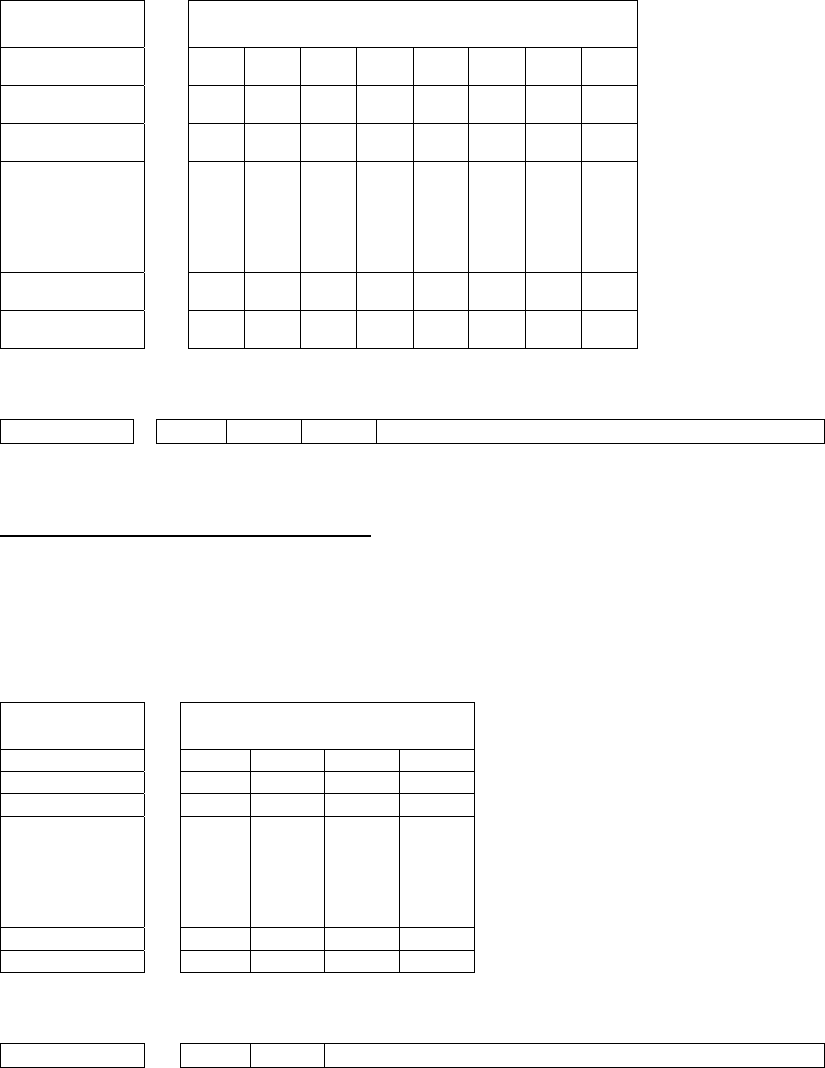
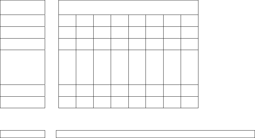
Figure 9 - Memory Structure of the Mifare Standard 4K (MF1 IC S70)
BYTE
BLOCK SECTO
R 15 14 13 12 11 10 09 08 07 06 05 04 03 02 01 00
0 Serial Number Check
Byte Manufacturer Data
1 Data
2 Data
3
0
Key A Lock Bits Key B
4 Data
5 Data
6 Data
7
1
Key A Lock Bits Key B
.
.
.
.
.
.
.
.
.
60 Data
61 Data
62 Data
63
15
Key A Lock Bits Key B
The complete Mifare specification can be obtained from the Philips publication “Mifare Standard 4 kByte
Card IC MF1 IC S70” dated October 2002.
Note: Only the tag serial number can be read by the CF RFID Reader Card.
42
Mifare Ultralight (Philips)
The complete Mifare Ultralight specification can be obtained from the Philips publication “Mifare
Ultralight Contactless Single-trip Ticket IC MF0 IC U1 Functional Specification” dated March 2003.
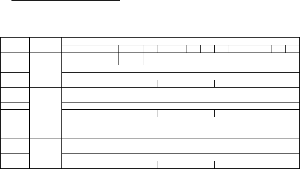
Figure 10 - Memory Structure of the Mifare Ultralight (MF0 IC U1)
Byte
Block 00 01 02 03
0 SN0 SN1 SN2 BCC0
1 SN3 SN4 SN5 SN6
2 BCC1 Internal Lock 0 Lock 1
3 OTP 0 OTP 1 OTP 2 OTP 3
4 Data 0 Data 1 Data 2 Data 3
.
.
.
.
.
.
15 Data 44 Data 45 Data 46 Data 47
System Area
User Area
Note: Only the tag serial number can be read by the CF RFID Reader Card.
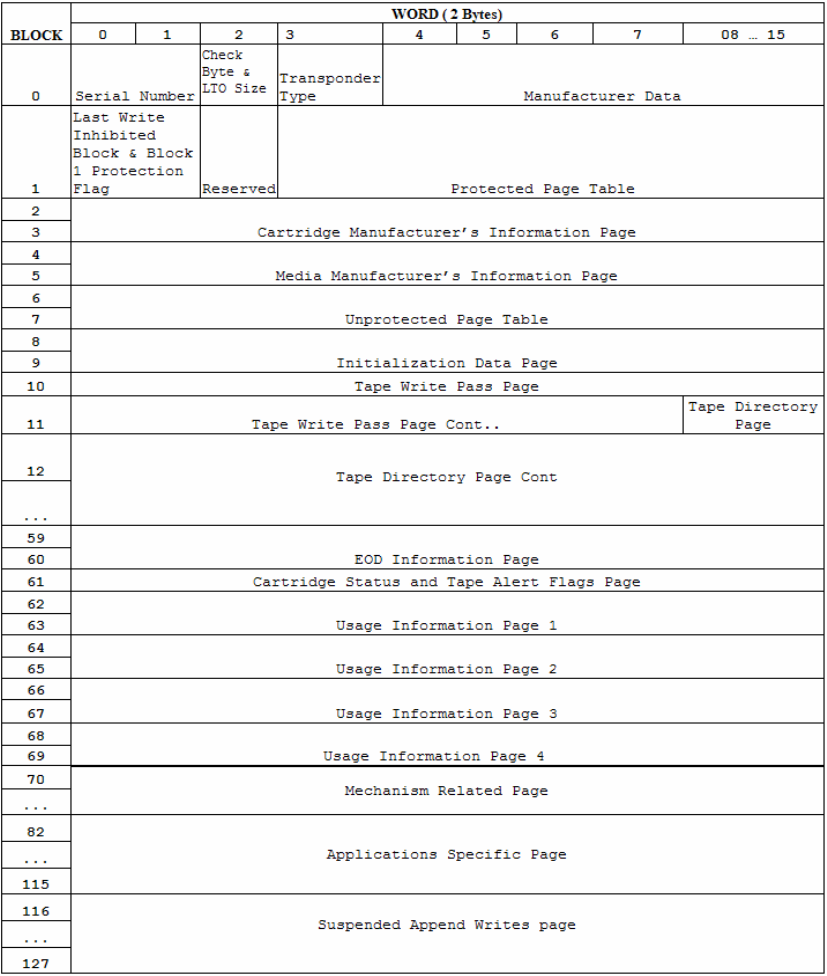
LTO CM 14443-A (LTO) The LTO-CM is compliant with ISO14443-A air interface.
Figure 12 - Memory Structure of the LTO CM
128 blocks of 32 bytes = 4096 bytes (32768 bits) of user memory is available for read/write.
Note: Only the tag serial number can be read by the CF RFID Reader-Scan Card.
APPENDIX B: HF RFID STANDARDS AND TAG DESCRIPTIONS 43
Appendix C
Bar Code Label Specifications
All bar code symbols/labels should satisfy the appropriate AIM Uniform
Symbology Specification.
Background Substrate:
The bar code symbol should be printed on material (media) that is reflective
and has a matte (not glossy) finish. A background diffuse reflectance of at
least 70% to 80% is desirable for optimum contrast. Retro-reflective media
should be used to obtain decode distances greater than 36 inches.
Ink Color and Type:
The inked bars should not exceed 25% reflectance at the wavelength that is
being used for reading, whether printed with black ink or colored ink. The
reflectance value should not vary more than 5% within the same character.
Voids and Specks:
The code should be printed clearly, free of voids, specks, blemishes and
lines that could “fool” the scanner. Specks or blemishes in the white
spaces, or false or missing bar sections could be interpreted by the reading
equipment as part of the code. Generally, the width of such flaws is more
serious than the height. Code symbols/ labels should be rejected if these
defects are present.
Definition:
The bars in the bar code symbol should be well defined. Their edges
should not be rough or fuzzy, so that the bars and spaces have the proper
widths intended for the bar code symbology used.
Contrast:
Background reflectance (that of the substrate on which the codes are
printed) should always provide a good contrast relative to the ink
reflectance (that of the code bars). The difference between the two should
be at least 37.5% at the wavelength used for reading.
Tolerance:
The ratio of the widths of bars and spaces in a bar code symbol must
conform to the appropriate AIM bar code specifications and can cause
problems if not correct throughout the bar code. Problems can occur when
bar edges are smeared or rough, or when they exhibit voids.
44 | APPENDIX B: SAFETY AND USAGE TIPS

Appendix D
Class 1 vs. Class 2 Laser Scanners
This is a paper on bar code laser scanners that Jack Brandon, Product
Marketing Manager of Scanner Products for Socket Communications,
published in 2001. You can download a copy of this paper from:
www.socketcom.com/support/learn.asp
Introduction
Socket now offers the popular CF RFID Reader-Scan Card with either a
CMOS, Class 1 or Class 2 laser engine. This document describes the
differences between the Class 1 and Class 2 devices and the appropriate
applications for each.
The primary difference is the power output of the laser. The Class 1 laser
has a nominal power output of 0.5 milliwatts, while the output of the Class 2
laser is 1.2 milliwatts. This difference impacts the scanning performance of
the device in three ways:
1. Distance — For scanning distances of up to 10 inches, there is very
little difference in the ability of either the Class 1 or the Class 2 laser to
scan a given bar code. Beyond 10 inches, the Class 2 laser will scan a
standard, high quality bar code about 20% - 25% farther than the Class
1 laser.
Scanning a standard bar code of any size at a distance greater than 25
inches becomes difficult with the Class 1 laser, while the Class 2 laser
will easily scan very large bar codes at 60 inches and beyond. There
are a many variables involved in determining the distance at which a
bar code can be scanned, including:
a. The size of the bar code — The width of the narrowest bar in
thousandths of an inch (or ‘mils’) is referred to as the “X
dimension” or “size” of a bar code. Standard retail UPC or EAN
bar codes are 10 mils (0.010 inches). Larger bar codes, such as
warehouse location bar codes, can be 200 mils or larger. The
larger a bar code, the greater the distance from which it can be
scanned.
Please refer to the Decode Zone charts in Appendix F for more
detailed information on the relationship between the size of a bar
code and the distance at which it can be scanned.
APPENDIX C: BAR CODE LABEL SPECIFICATIONS | 45

b. The label media — The media is the material a bar code is printed
on. This is usually some type of paper but can also be a plastic or
even metallic material. Because the reading mechanism in a bar
code scanner is based on contrast, the whiter and more reflecting a
media is, the farther away it can be scanned. Retro-reflective
media (like a stop sign) is used for scanning very large bar code
labels at distances of 20 feet and more.
c. The bar code symbology — There are many different bar code
symbologies (or ‘languages’), such as UPC, EAN, Code 39, Code
128, Code 93 and more. Some symbologies are easier to decode
than others and can, therefore, be scanned at greater distances.
2. Packaging or covering materials — The Class 2 laser can more
effectively scan through difficult packaging materials such as Mylar
(used for electronic components) or thick plastic or glass such as
automobile windshields.
3. Ambient light — The Class 2 laser can more effectively scan in high
ambient light conditions such as high intensity lighting or even daylight
(indirect sunlight). Scanning bar codes in direct sunlight is extremely
difficult because sunlight contains enough energy in the red spectrum
used by the laser to ‘blind’ the scanner’s decode system.
The second difference between the Class 1 and Class 2 lasers in the Socket
CF RFID Reader-Scan Card is the wavelength frequency of the laser beam.
The Class 1 laser has a 670 nanometer (nm) beam common in most laser bar
code scanners, while the Class 2 features a 650 nm beam. There is no
difference in the scanning capability of the two frequencies, but the 650 nm
beam is more visible to the human eye, making it appear brighter than the
Class 1 laser.
The user must see the oscillating laser beam in order to aim it effectively at
the bar code to be scanned. The Class 2, 650 nm laser is easier to see and
aim than the Class 1 laser, especially when scanning at greater distances,
through difficult materials or in high ambient light.
A third difference between the Class 1 and Class 2 lasers is the current
demand during scanning. At 3.3 Volt power (standard for CompactFlash
card slots) the Class 1 laser draws about 67 milliamps (mA) and the Class 2
laser draws about 75 mA. Both lasers draw about 3 – 4 mA when idle.
Therefore, for a given level of scanning activity, using the Class 1 laser
should result in a slightly longer battery life.
A final consideration in the selection of either a Class 1 or Class 2 laser is
safety. Staring directly into any laser beam for an extended period of time
46 | APPENDIX C: BAR CODE LABEL SPECIFICATIONS
will cause damage to the eyes of humans and animals. The normal use of a
bar code scanner is inherently very safe because (a) the laser is typically
aimed away from the person using the scanner, and (b) the beam oscillates
39 times per second over a 53° arc, making it impossible to stare into the
beam. Additionally, using the lower powered Class 1 laser makes it even
less likely that eye damage will occur. There are certain organizations in
Europe, in fact, that require a Class 1 laser in bar code scanners to meet
more stringent safety standards. The Socket CF RFID Reader-Scan Scan
Card with Class 1 laser meets these European safety standards. Please refer
to the Regulatory Compliance section at the end of this User’s Guide for
more detailed safety information.
Conclusion
The Class 1 laser is suitable for most applications with expected scanning
distances of less than 20 inches and normal ambient light conditions. The
Class 1 laser may be required by certain European organizations to meet
more stringent safety standards. When an application is likely to require
more demanding scanning capabilities, the Class 2 laser provides the
assurance of maximum scanning performance.
Note: People who use portable computers to gather and manage data at the
point of activity are typically very quick to learn how to use a laser bar code
scanner and realize the resulting gains in productivity. They are easily
discouraged, however, if time and effort are required to obtain a successful
scan – thus the decline in popularity of the much less expensive bar code
contact wands seen at most retail checkout counters during the 1980’s. The
higher cost of the Class 2 version of the CF RFID Reader-Scan Card is
easily justified if the application requires higher scanning performance.
APPENDIX C: BAR CODE LABEL SPECIFICATIONS | 47
Appendix E
Enabling or Disabling Symbologies
All Socket bar code scanning products are pre-set to automatically detect
and decode (autodiscriminate) the most common bar code symbologies.
Refer to the table on the next page to determine which symbologies and
parameters are set as default. If you would like to change your symbology
settings, you can choose from either of two options, depending on what
device you are using and what settings you want to change.
Note: With more symbologies enabled, the scanner must work harder to
search through all the possible combinations. This may make the decoding
process slightly longer.
OPTION 1: Symbology Selector for Windows Mobile
If you are using a Windows Mobile-based device, you can quickly enable
and disable any of the seventeen most popular symbologies by using the
SocketScan Symbology Selector. Refer to Chapter 2 for instructions.
Note: The length of some symbologies will change after Symbology Selector
is used. Refer to the table on the next page.
OPTION 2: Scan Programming Bar Codes
If you want to modify an option not included in Symbology Selector, you
can scan programming bar codes to configure your CF RFID Reader-Scan
Card. There are a variety of programming bar codes available that let you
enable/disable symbologies as well as configure special features (e.g.,
specify bar code lengths, transmit check digits, recognize supplementals,
etc.).
To obtain the programming bar codes, download the Programming Guide
online from www.socketcom.com/support/support_bar.asp.
WARNING!
When scanning programming bar codes with the CF
RFID Reader-Scan Card, do not scan any bar codes
that set communication protocols, as the CF RFID
Reader-Scan Card will be disabled and must be
returned to Socket for reprogramming.
48 | APPENDIX D: ENABLING/DISABLING SYMBOLOGIES
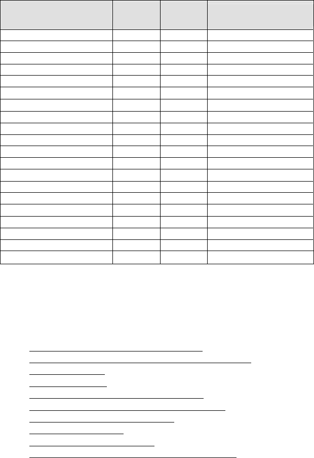
Table 1. Default Symbologies and Settings of the CF RFID Reader-Scan Card
Symbology Default Length Length with
Symbology Selector
UPC-A Enabled N/A N/A
UPC-E Enabled N/A N/A
UPC-E1 Disabled N/A N/A
EAN-8 Enabled N/A N/A
EAN-13 Enabled N/A N/A
• Supplementals Disabled N/A N/A
• Transmit Check Digit Enabled N/A N/A
Bookland EAN Disabled N/A N/A
Code 128 - All Enabled Any Any
Code 39 Enabled 2 to 55 2 to 55
Trioptic Code 39 Disabled 2 to 55 2 to 55
Code 39 Full ASCII Disabled 2 to 55 2 to 55
• Transmit Check Digit Disabled N/A N/A
Code 93 Disabled 4 to 55 2 to 55
Interleaved 2 of 5* Enabled 14 Only 2 to 55
• Transmit Check Digit Disabled N/A N/A
Discrete 2 of 5* Disabled 12 Only 2 to 55
Codabar Disabled 5 to 55 2 to 55
MSI Plessey* Disabled 6 to 55 2 to 55
• Transmit Check Digit Disabled N/A N/A
*WARNING: Setting the length to “Any” may lead to inaccurate decodes in these
symbologies
For more information on bar codes, symbologies, labels or other bar code
related topics, visit any of the following web sites:
a. www.aimglobal.org/technologies/barcode/
b. www.aimglobal.org/aimstore/stackedsymbologies.htm
c. www.adams1.com
d. www.bizfonts.com
e. www.barcode-us.com/info_center/upc.htm (UPC Codes)
f. www.barcode-us.com/info_center/bookinfo.htm (Bookland EAN)
g. www.dataid.com/bcsymbology.htm
h. www.aaabarcodes.com
i. www.snx.com/mechanics.html
j. www.idautomation.com/barcoding4beginners.html
APPENDIX D: ENABLING/DISABLING SYMBOLOGIES | 49
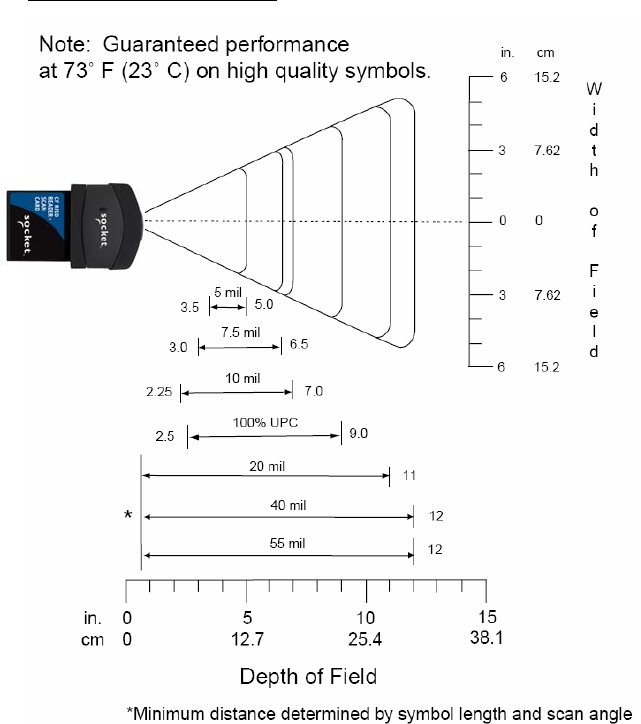
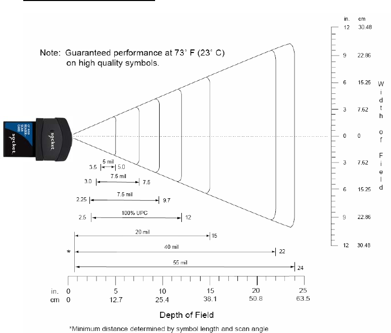
Appendix F
Laser Decode Zone
The decode zones for the Class 1 and Class 2 lasers in the CF RFID Reader-
Scan Card are shown below. The minimum element width (“X Dimension”
or bar code “size”) is the width in thousandths of an inch (mils) of the
narrowest element (bar or space) in the symbol. The figures shown are the
typical scanning distances (depths of field) for selected bar code sizes. The
maximum usable length of a bar code symbol (Width of Field) at any given
range is also shown below.
Class 1 Laser Decode Zone
50 | APPENDIX E: DECODE ZONE
Class 2 Laser Decode Zone
APPENDIX E: DECODE ZONE | 51
Appendix G
Troubleshooting
For help on SocketScan on a Windows Mobile-based device, tap Start | Help.
SYMPTOM:
I get the “No Card Detected” icon in the task tray and
can’t trigger the laser or scan any bar codes.
POSSIBLE REASON SOLUTION
Your mobile computer does not
recognize the RFID Reader-
Scan Card.
Make sure the RFID Reader
Card is inserted properly. If
necessary, remove and
reinsert. If using battery power,
be sure to tap Yes if asked if
you want to use battery power.
SYMPTOM:
When I try to read an RFID tag, no data appears on my
screen.
POSSIBLE REASON SOLUTION
You are holding the Pocket PC
and RFID Reader-Scan Card in
the wrong position..
Hold the Pocket PC so the
RFID Reader-Scan Card is
parallel to and directly above
the RFID tag, at most 2.5
inches above the tag.
The RFID tag antenna is
broken or incorrectly formatted. Try reading another RFID tag
that is correctly formatted.
The tag type may be disabled. Use RFID Demo to determine
the tag type. If needed,
reconfigure the RFID Reader-
Scan Card for the correct tag
type.
SYMPTOM:
When I press the trigger button, nothing happens.
POSSIBLE REASON SOLUTION
You programmed the trigger
button incorrectly. Test the button by assigning a
different program to it and make
sure it works properly.
52 | APPENDIX C: TROUBLESHOOTING
Appendix H
Technical Support
If you have trouble installing or using RFID Reader-Scan Card, Socket has
two technical support resources to help you. Please note that technical
support is available in English only.
1. Socket On-Demand Support (SOS)
Socket On-Demand Support is an interactive technical
support program that focuses in on your specific
problem to provide the answers you need. SOS
provides immediate service and is the best place to start for technical
support. To access SOS, visit: www.socketcom.com/support. Click on
the SOS icon.
If SOS cannot solve your problem, end the session by submitting an
email inquiry to a Socket technical support engineer as prompted. Your
interactive session will be saved for reference.
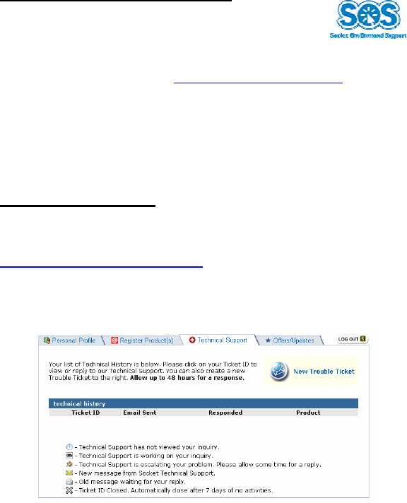
2. Live Technical Support
IMPORTANT! To obtain technical support, you must first
register your product online at
www.socketcom.com/prodreg.
After you register your product, log in and click on the Technical
Support tab. Click New Trouble Ticket.
If we are unable to resolve your support inquiry online, we can arrange
for a technical support representative to call you at a specific time.
Please refrain from disassembling the Socket RFID Reader-Scan Card.
Disassembly of this device will void the product warranty.
APPENDIX D: TECHNICAL SUPPORT | 53
Limited Warranty
Socket Communications Incorporated (Socket) warrants this product against defects
in material and workmanship, under normal use and service, for the following
period from the date of purchase:
Socket CF RFID Reader-Scan Card: Two years
Incompatibility is not a defect covered by Socket’s warranty. During the warranty
period, Socket will, at its option, repair or replace the defective product at no charge
when furnished with proof of retail purchase, provided that you deliver the product
to Socket or to an authorized Socket Service Center.
The returned product must be accompanied by a return material authorization
(RMA) number issued by Socket or by Socket's Authorized Service Center. If you
ship the product, you must use the original container or equivalent and you must pay
the shipping charges to Socket. Socket will pay shipping charges back to any
location in the contiguous United States. This warranty applies only to the original
retail purchaser and is not transferable.
Socket may, at its option, replace or repair the product with new or reconditioned
parts and the returned product becomes Socket's property. Socket warrants the
repaired or replaced products to be free from defects in material or workmanship for
ninety (90) days after the return shipping date, or for the duration of the original
warranty period, whichever is greater.
This warranty does not cover the replacement of products damaged by abuse,
accident, misuse or misapplication, nor as a result of service or modification other
than by Socket.
SOCKET IS NOT RESPONSIBLE FOR INCIDENTAL OR CONSEQUENTIAL
DAMAGES RESULTING FROM BREACH OF ANY EXPRESS OR IMPLIED
WARRANTY, INCLUDING DAMAGE TO PROPERTY AND, TO THE EXTENT
PERMITTED BY LAW, DAMAGES FOR PERSONAL INJURY. THIS
WARRANTY IS IN LIEU OF ALL OTHER WARRANTIES INCLUDING
IMPLIED WARRANTIES OF MERCHANTABILITY AND FITNESS FOR A
PARTICULAR PURPOSE.
Some states do not allow limitation of implied warranties, or the exclusion or
limitation of incidental or consequential damages, so that the above limitations or
exclusions may not apply to you. This warranty gives you specific legal rights and
you may also have other rights which vary from state to state.
This product may contain fully tested, recycled parts, warranted as if new.
For warranty information, call (510) 744-2700.
54
Limited Software Warranty
LIMITED WARRANTY. SOCKET warrants that the original disk or CD ROM is
free from defects for 90 days from the date of delivery of the SOFTWARE.
CUSTOMER REMEDIES. SOCKET’S entire liability and your exclusive remedy
shall be, at SOCKET’S option, either (a) return of the price paid or (b) replacement
of the SOFTWARE which does not meet SOCKET’S Limited Warranty and which
is returned to SOCKET with a copy of your receipt. Any replacement SOFTWARE
will be warranted for the remainder of the original warranty period or 30 days,
whichever is longer. THESE REMEDIES ARE NOT AVAILABLE OUTSIDE OF
THE UNITED STATES OF AMERICA.
NO OTHER WARRANTIES. SOCKET disclaims all other warranties, either
express or implied, including but not limited to implied warranties of
merchantability and fitness for a particular purpose, with respect to the
SOFTWARE and the accompanying written materials. This limited warranty gives
you specific legal rights. You may have others which vary from state to state.
NO LIABILITY FOR CONSEQUENTIAL DAMAGES. In no event shall SOCKET
or its suppliers be liable for any damages whatsoever (including, without limitation,
damages for loss of business profits, business interruption, loss of business
information, or other pecuniary loss) arising out of the use of or inability to use the
SOFTWARE, even if SOCKET has been advised of the possibility of such
damages. Because some states do not allow the exclusion or limitation of liability
for consequential or incidental damages, the above limitation may not apply to you.
EXPORT LAW ASSURANCES. You may not use or otherwise export or re-export
the SOFTWARE except as authorized by United States law and laws of the
jurisdiction in which the SOFTWARE was obtained. In particular, but without
limitation, none of the SOFTWARE may be used or otherwise exported or re-
exported (a) into (or to a national or resident of) a United States embargoed country
or (b) to anyone on the U.S. Treasury Department’s list of Specially Designated
Nationals or the U.S. Department of Commerce’s Table of Denial Orders. By using
the SOFTWARE, you represent and warrant that you are not located in, under
control of, or a national or resident of any such country or on any such list.
GOVERNMENT END USERS. If the SOFTWARE is supplied to the U. S.
Government, the SOFTWARE is classified as “restricted computer software” as
defined in clause 52.227-19 of the FAR. The U. S. Government ‘s rights to the
SOFTWARE are as provided in clause 52.227-19 of the FAR.
CONTROLLING LAW AND SEVERABILITY. This License shall be
governed by the laws of the United States and the State of California. If for
any reason a court of competent jurisdiction finds any provision, or portion
thereof, to be unenforceable, the remainder of this License shall continue in
full force and effect.
55

Regulatory Compliance
This device complies with part 15 of the FCC Rules. Operation is subject to
the following two conditions: (1) This device may not cause harmful
interference, and (2) this device must accept any interference received,
including interference that may cause undesired operation.
Changes or modifications not expressly approved by the party responsible
for compliance could void the user's authority to operate the equipment.
PRODUCT DISPOSAL: This product must not be disposed of with
municipal waste. It is your responsibility to dispose of your waste
equipment by handing it over to a designated collection point for the
recycling of waste electrical and electronic equipment.
56
© Socket Communications, Inc. 9/2005 Printed in U.S.A.