SolarEdge Technologies PLNX Linus communication board User Manual rev
SolarEdge Technologies Ltd Linus communication board Users Manual rev
Users Manual_rev.pdf
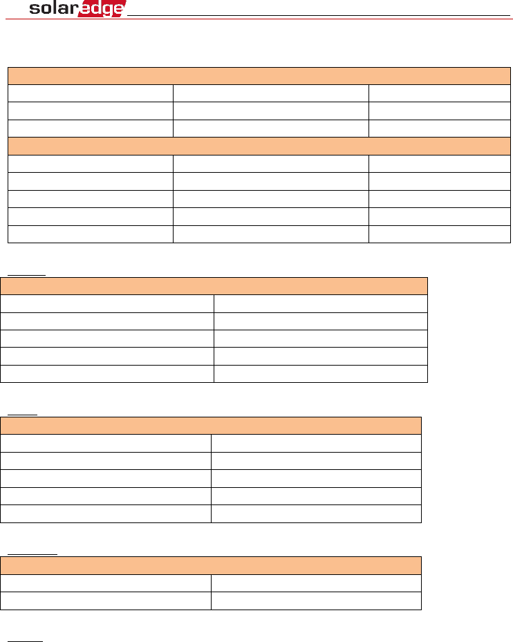
Specifications
Model: 2AGPT-PLNX
Power
Input Voltage
5
Vdc
Connector Type
Micro-fit
Power Consumption
<3
W
Communication interfaces
RS485 Interfaces
2 ports
Ethernet Interface
10/100-BaseT
Wi-Fi interface
802.11b/802.11g/802.11n
ZigBee interface
O-QSPK
Power reducer
4/6 pin control, 5V
ZigBee
Technical Information ZigBee
Operating Frequencies
2.4 GHz -2.48GHz
Bandwidth
2.25MHz
Clock Frequency
38.4MHz
Maximum RF Power
18.85dBm
Antenna Gain
5dBi
Wi-Fi
Technical Information Wi-Fi
Operating Frequencies
2.4 GHz -2.48GHz
Bandwidth
20MHz
Clock Frequency
26 MHz
Maximum RF Power
11.32dBm
Antenna Gain
5dBi
Ethernet
Technical Information Ethernet
Clock Frequency
50MHz
Mode operating
100BASE-TX
RS485
The Linux communication board can be connected to another SolarEdge unit (inverter,
another communication board) by RS485. Baud Rate frequency 115200Hz.
Activating, Commissioning and
Configuring the System Using SolarEdge
Inverter SetApp
If applicable, you can connect communication options at this stage.
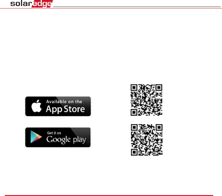
Once all connections are made, the system should be activated and commissioned
using the SolarEdge Inverter SetApp mobile application. You can download the app
from the iTunes and Google Play app stores prior to reaching the site.
Internet connection is required for the download and for the one-time registration,
however not required for using SetApp.
Step 1: Activating
During system activation, a Wi-Fi connection is created between the mobile device
and the Linux communication board.
Before activation - download, register (first time only) and log-in to SetApp on your
mobile device.
► To activate the installation:
1 Turn ON the Linux communication board.
2 Open SetApp and follow the instructions on the screen (scan the Linux
communication board bar-code, usually located on inverter; move the ON/OFF/P
switch to P position and release within 5 sec. back to ON (1) position). SetApp creates
a Wi- Fi connection, upgrades the inverter CPU firmware and activates the inverter.
Step 2: Commissioning and Configuring the
Installation
This section describes how to use the SetApp menus for commissioning and
configuring the Linux communication board settings.
Menus may vary in your application depending on your system type.
► To access the Commissioning screen:
Do one of the following:
▪
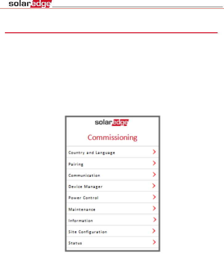
During first time installation: Upon Activation completion, in the
SetApp, tap
Start Commissioning
.
The main Commissioning menu screen is displayed:
▪
If the Linux communication board has already been activated and
commissioned:
1.
If not already ON - turn ON AC to the inverter by turning ON the circuit breaker on
the main distribution panel.
2.
If not already ON - move the Connection Unit switch to the ON position.
3.
Open SetApp and follow the instructions on the screen (scan the Linux
communication board bar-code, usually located on the inverter; move the
ON/OFF/P switch to P position (for less than 5 sec) and release).
4.
The mobile device creates a Wi-Fi connection with the Linux communication board
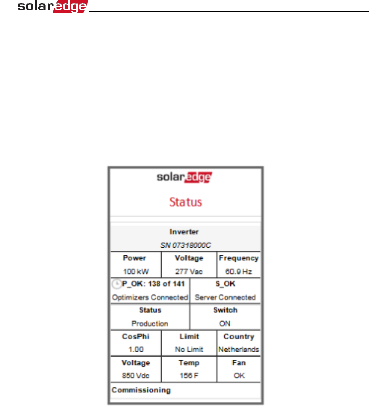
and displays the main Status screen.
5.
Tap Commissioning at the bottom of the screen. The main Commissioning menu
screen is displayed.
In the main menus, tap the menu red arrows (›) to perform the system
commissioning or configuration task. Tap the Back arrow (‹) to return to the
previous menu.
The next sections provide more information about configuration options.
Setting Country and Language
1 From the Commissioning screen select Country and Language.
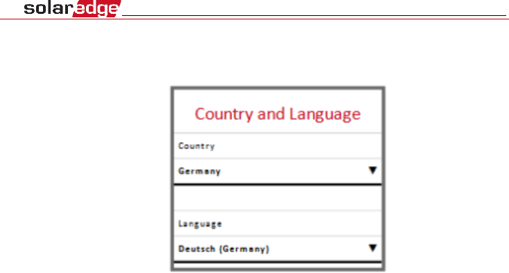
2 From the Country drop-down list, select the required country setting.
1.
From the Language drop-down list, select the language.
2.
Tap OK.
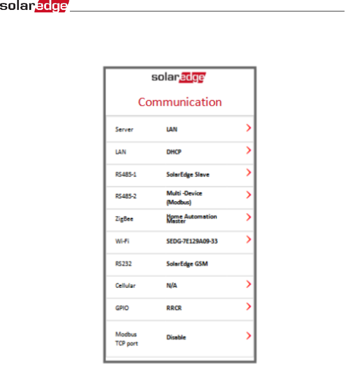
Communication
1.
Select the Communication menu to define and configure the following:
•
The communication option used by the inverter to
communicate with the SolarEdge monitoring
platform
•
The communication option used to communicate
between multiple SolarEdge devices or other
external
non-SolarEdge devices, such as electricity meters or
loggers.
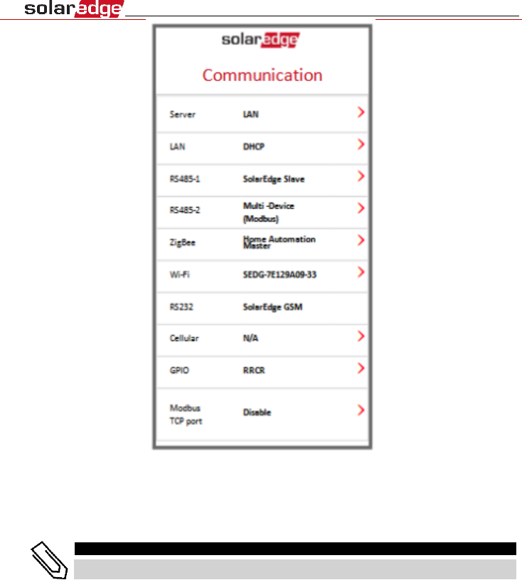
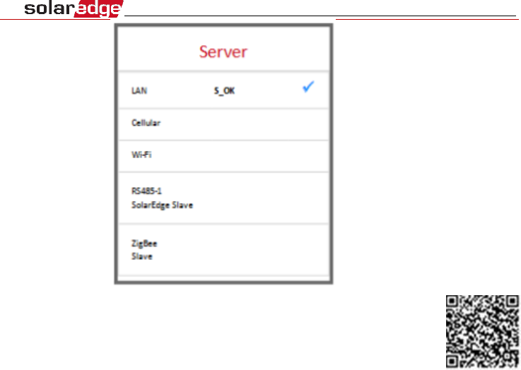
2.
Tap the Server red arrow to set the communication method to be used for
communication between devices and the SolarEdge monitoring platform. The
default is LAN. Refer to Setting Up Communication for a full description of these
communication options.
NOTE
The Server menu shows only the communication options installed in the inverter.
For detailed information about all the configuration options, refer to
the Communication Options Application Note, available on the
SolarEdge website at
https://www.solaredge.com/sites/default/files/solaredge-
communication_options_application_note_v2_250_and_above.pdf.
Information
From the main menu, select Information to view and set various system settings, as
described below.
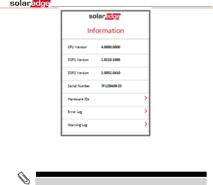
•
CPU Version
: The communication board firmware
version
•
DSP 1/2 Version
: The digital board firmware version
NOTE
Please have these numbers ready when you contact SolarEdge Support.
•
Serial Number
- The inverter serial number as appears on
the enclosure sticker
•
Hardware IDs
: Displays the following HW serial numbers
(if exist, and connected to the inverter):
o
This inverter
: the inverter's ID
o
Meter #
: Modbus meter ID (up to 3 meters can be
connected)
o
ZB
: ZigBee Card MAC address
o
WiFi
: Wi-Fi MAC address
•
Error Log
: Displays the last five errors, and enables
resetting (clearing) the log.
•
Warning Log:
Displays the last five warnings, and enables
resetting (clearing) the log.
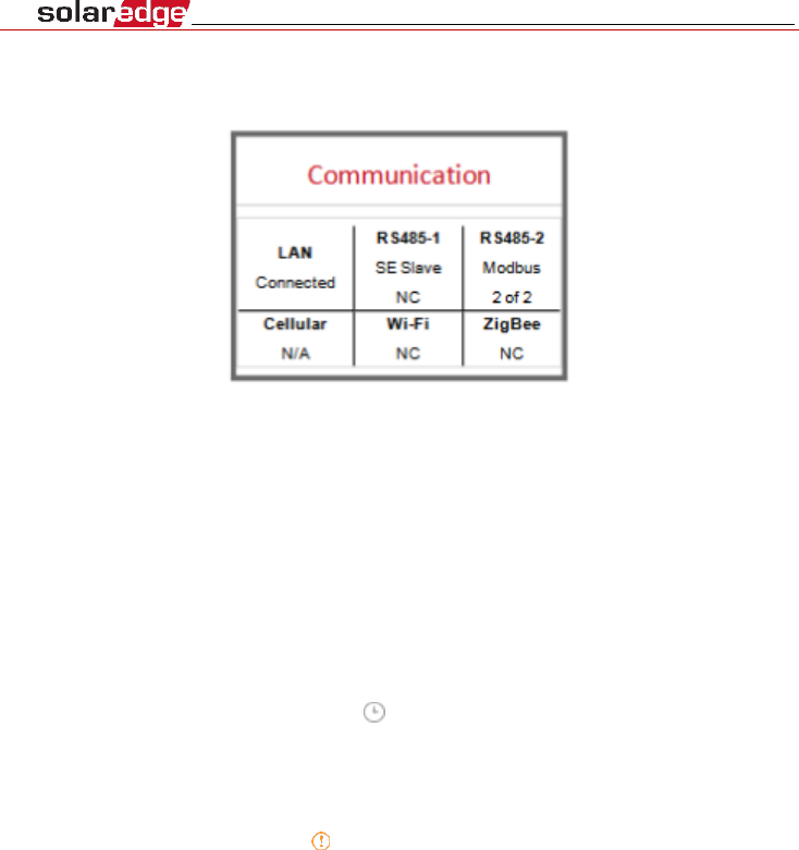
Communication Status
This screen displays the status of connection option(s): LAN, RS485, Wi-Fi, GSM or
ZigBee card.
For each communication option, one of the following statuses is displayed:
•
Connected
: The inverter established a successful
connection and communication with the specified server
port/device
•
NC
: Not Connected.
•
S_OK
: The connection to the SolarEdge monitoring
platform is successful (should appear only if the
inverter is
connected to the server)
•
N/A
: Not Applicable
•
x of y
: Number of devices connected out of all devices
•
Temporarily displayed (with a
clock sign):
o
Initializing communication
o
Connecting
to a network
o
Connecting
to SolarEdge servers
•
Error message
(with the
sign).
Setting Up Communication
The inverter sends the following information to the monitoring platform:
▪
Power optimizer information received via the DC power lines
(the PV output circuit)
▪
Inverter information
▪
Information of any other connected devices
This chapter describes setting up communication between:
▪
the inverter and the monitoring platform through the Internet
(wired/ wireless), or through a cellular
connection
▪
multiple inverters for a master/slave configuration
Communication setup is not required for power harvesting, however it is needed
for using the SolarEdge monitoring platform.
NOTE
It is recommended to connect communication connections before connecting the
AC, for easier access to the communication board.
CAUTION!
When connecting the communication cables, make sure that the ON/OFF/P switch at
the bottom of
the inverter is turned OFF, and the AC is turned OFF.
When configuring the communication parameters, make sure that the ON/OFF/P
switch is in P
position, and the AC is turned ON.
When connecting the communication cables, make sure that the ON/OFF/P switch on
the Connection Unit is turned OFF, and the AC is turned OFF.
When configuring the communication parameters, make sure that the ON/OFF/P
switch on the Connection Unit is OFF, and the AC is turned ON.
Communication Options
The following types of communication can be used to transfer the monitored to
the SolarEdge monitoring platform.
Only communication products offered by SolarEdge are supported.
Ethernet
Ethernet is used for a LAN connection
RS485
RS485 is used for the connection of multiple SolarEdge devices on the same bus in a
master-slave
configuration. RS485 can also be used as an interface to external
devices, such as meters and third party data loggers.
▪
RS485-1: Enables the connection of multiple inverters over the
same bus, such that connecting
only one inverter to the Internet
is sufficient to provide communication services for all the
inverters on the bus. RS485-1 has built-in surge protection.
▪
RS485-2: Enables connection of non-SolarEdge devices.
Wi-Fi/ZigBee
Wi-Fi and ZigBee are implemented in the Linux communication board.
GSM
This wireless communication option (purchased separately) enables
using a GSM connection to connect one or several devices (depending
on the data plan used) to the
SolarEdge monitoring platform.
The GSM cellular modem is provided with a user manual, which
should be reviewed prior to connection. Refer to
http://www.solaredge.com/sites/default/files/cellular_
gsm_installation_guide.pdf
Linux Communication Board
Primary Unit Communication Board
Use this communication board to:
▪
GSM- connect a GSM modem.
▪
RS485-1 - connected to the Connection Unit communication
board. For connecting
multiple inverters over the same bus,
connect RS485 wires to the terminal blocks on the Connection
Unit Communication Board.
▪
RS485-2 - connect a non-SolarEdge device, such as a meter or a
third party data logger, to the RS485-2
connector. Every pair of in
and out wires are connected to the same pin.
▪
Power Reduction Interface (PRI) - connect a power reduction
device. See application_note_power_
control_configuration.pdf
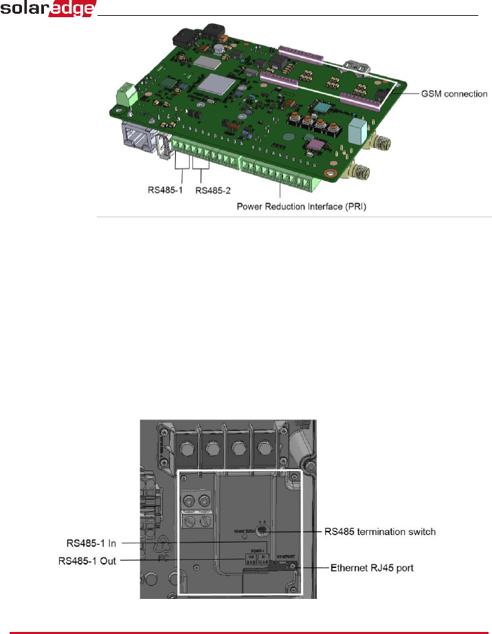
Connection Unit Communication Board
Use this communication board to:
▪
connect a standard RJ45 connector for Ethernet.
▪
connect RS485 wires to the terminal blocks for RS485
connection. There are two 3-pin terminal blocks, one for
connecting the preceding device in the bus and one for
connecting the following
device. Additionally, the RS485 port
has a built-in surge protection.
Creating an Ethernet (LAN) Connection
This communication option enables using an Ethernet connection to connect the
Linux communication board to the
monitoring platform through a LAN.
Ethernet cable specifications:
▪
Cable type – a shielded Ethernet cable (Cat5/5E STP) may be used
▪
Maximum distance between the inverter and the router – 100
m/ 330 ft.
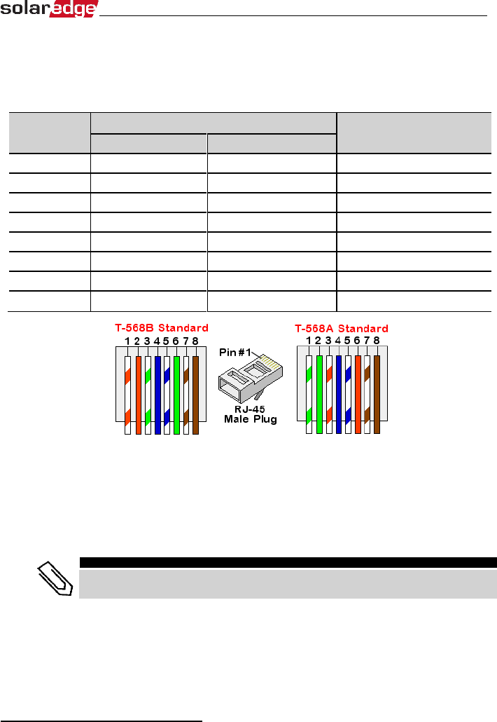
► To connect the Ethernet cable:
You can use either wiring standard, as long as both sides of the cable have the
same pin-out and color-coding.
RJ45 Pin #
Wire Color1
10Base-T Signal
100Base-TX Signal
T568B
T568A
1
White/Orange
White/Green
Transmit+
2
Orange
Green
Transmit-
3
White/Green
White/Orange
Receive+
4
Blue
Blue
Reserved
5
White/Blue
White/Blue
Reserved
6
Green
Orange
Received-
7
White/Brown
White/Brown
Reserved
8
Brown
Brown
Reserved
1 Connect the cable RJ45 connector to the RJ45 port of the Ethernet switch or router.
You can connect more than one Linux communication board to the same
switch/router or to different switches/routers, as needed. Each Linux
communication board sends its monitored data independently to the SolarEdge
monitoring platform.
NOTE
There are no LED indicators on the Ethernet connector, if the inverter is not
communicating with the monitoring platform through a LAN.
1
The connection does not support RX/TX polarity change. Supporting crossover Ethernet cables depends on the switch
capabilities.
2 The inverter is configured by default to LAN. If reconfiguration is required:
1.
Use the SolarEdge SetApp to access the Commissioning main menu screen
2.
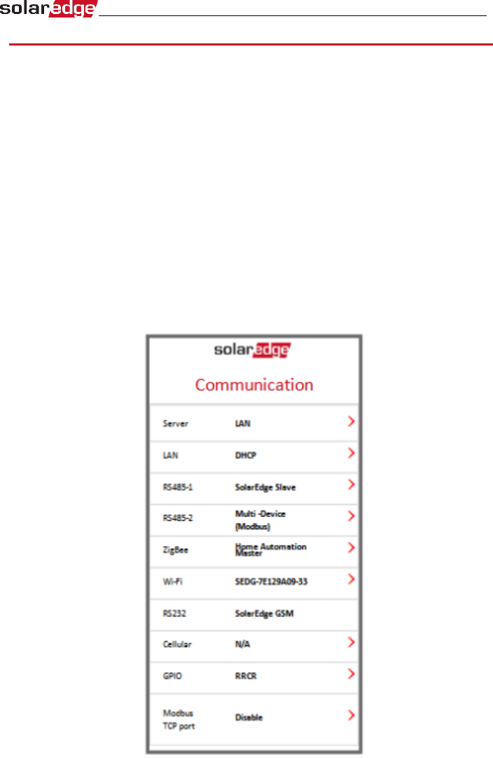
From the main menu tap Communication. The Communication screen is displayed:
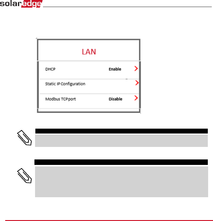
3.
Select the following to configure the connection:
•
Server
>
LAN
•
LAN
>
DHCP
>
Enable
4.
Verify the connection.
NOTE
The system automatically establishes communication with the monitoring
platform as it is configured to LAN by default.
NOTE
If your network has a firewall, you may need to configure it to enable the
connection to the following address:
•
Destination Address: prod.solaredge.com
•
Modbus TCP Port: 22222 (for incoming and outgoing data)
Creating an RS485 Bus Connection
The RS485 option enables creating a bus of connected Linux communication board,
consisting of up to 31 slave boards and 1 master. Using this option, Linux
communication boards are connected to each other in a bus (chain) via their RS485
connectors, thus allowing to connect only the master board to the monitoring
platform. The first and last board in the chain must be terminated.
RS485 wiring specifications:
▪
Cable type: Min. 3-wire shielded twisted pair (a shielded
Ethernet cable (Cat5/5E STP) may be used)
▪
Wire cross-section : 0.2- 1 mm²/ 24-18 AWG
▪
Maximum distance between first and last devices: 1 km /3300 ft.
The following sections describe how to physically connect the RS485 bus and how
to configure the bus.
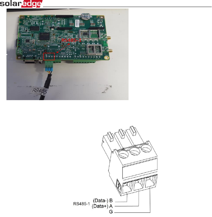
1 Loosen the screws of pins A(+), B(-), and G in either the 'Out' or 'In' RS485 terminal
block.
2 Insert the wire ends into the G, A and B pins shown above. Use one terminal block
for the previous Linux communication board in the bus and the other terminal block
for the next Linux communication board in the bus,. You can use any color wire for
each of the A, B and G connections, as long as the same color wire is used for all A
pins, the same color for all B pins and the same color for all G pins.
3 Tighten the terminal blocks screws.
4 Check that the wires are fully inserted and cannot be pulled out easily.
5 Push the RS485 terminal blocks firmly all the way into the connectors on the
communication board.
RS485 Bus Configuration
► To connect to the monitoring platform:
1.
Designate a single communication board as the connection point between the RS485
bus and the SolarEdge
monitoring platform. This board will serve as the master board.
2.
Connect the master to the SolarEdge monitoring platform via the LAN option or any
of the other options.
► To configure the RS485 bus:
All inverters are configured by default as slaves. To configure the master:
1.
Verify switch is OFF.
2.
Verify the AC is on.
3.
Turn ON the Connection Unit.
4.
Use SetApp to access the Commissioning main menu screen.
5.
From the main menu tap Communication. The Communication screen is displayed:
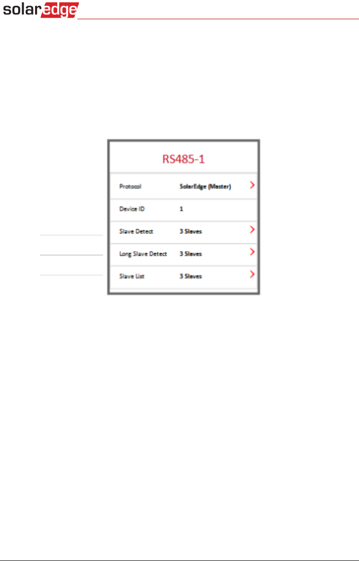
6.
Select the following to configure the connection:
•
Server
>
LAN
•
RS485-1
>
Protocol
>
SolarEdge Master
•
RS485-1
>
Slave Detect
The system starts automatic detection of the SolarEdge slave inverters connected
to the master inverter. The inverter should report the correct number of slaves. If
it does not, verify the connections and terminations.
7.
To check the slave IDs and last communication time, select
RS485-1
>
Slave List
.
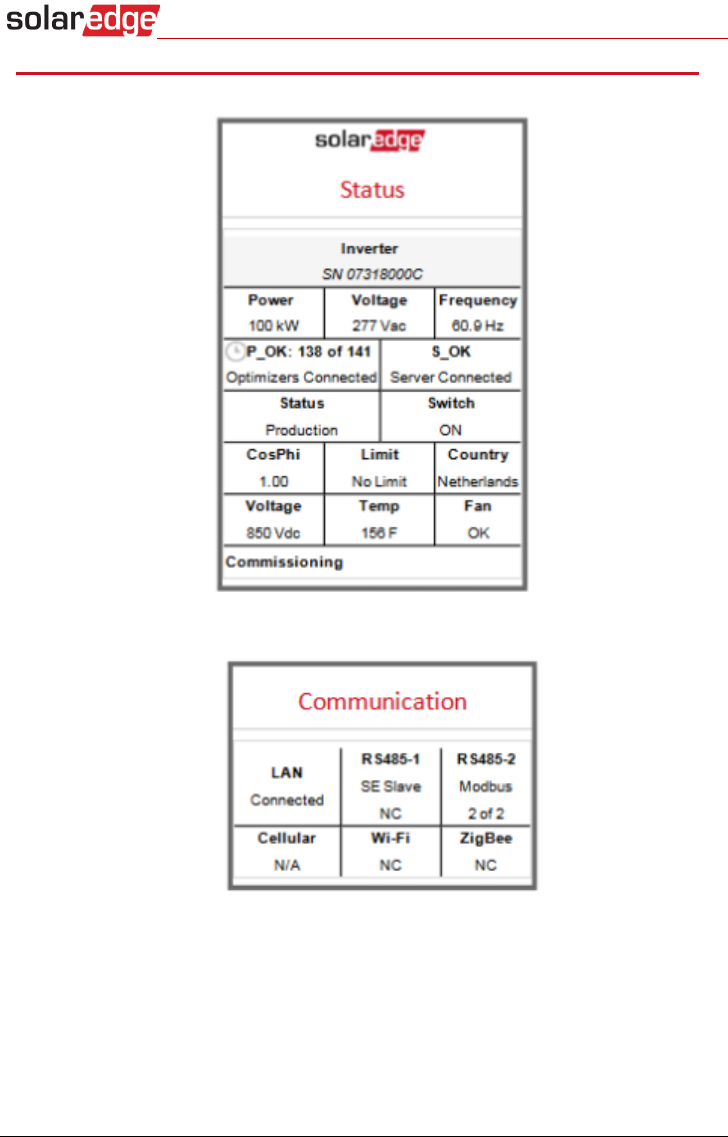
Verifying the Connection
1.
Check that S_OK - Server Connected status appears in the main inverter section:
2.
Scroll down to the Communication section and check that the communication
options are as required.

Federal Communication Commission Interference Statement
This device complies with Part 15 of the FCC Rules. Operation is subject to the following two conditions: (1) This device may not cause
harmful interference, and (2) this device must accept any interference received, including interference that may cause undesired
operation.
This equipment has been tested and found to comply with the limits for a Class B digital device, pursuant to Part 15 of the FCC Rules.
These limits are designed to provide reasonable protection against harmful interference in a residential installation. This equipment
generates, uses and can radiate radio frequency energy and, if not installed and used in accordance with the instructions, may cause
harmful interference to radio communications. However, there is no guarantee that interference will not occur in a particular
installation. If this equipment does cause harmful interference to radio or television reception, which can be determined by turning the
equipment off and on, the user is encouraged to try to correct the interference by one of the following measures:
- Reorient or relocate the receiving antenna.
- Increase the separation between the equipment and receiver.
- Connect the equipment into an outlet on a circuit different from that
to which the receiver is connected.
- Consult the dealer or an experienced radio/TV technician for help.
FCC Caution: Any changes or modifications not expressly approved by the party responsible for compliance could void the user's
authority to operate this equipment.
This transmitter must not be co-located or operating in conjunction with any other antenna or transmitter.
FOR MOBILE DEVICE USAGE (>20cm/low power)
Radiation Exposure Statement:
This equipment complies with FCC radiation exposure limits set forth for an uncontrolled environment. This equipment should be
installed and operated with minimum distance 20cm between the radiator & your body.
FOR COUNTRY CODE SELECTION USAGE (WLAN DEVICES)
Note: The country code selection is for non-US model only and is not available to all US model. Per FCC regulation, all WiFi product
marketed in US must fixed to US operation channels only.
This device is intended only for OEM integrators under the following conditions:
1)The antenna must be installed such that 20 cm is maintained between the antenna and users, and
2)The transmitter module may not be co-located with any other transmitter or antenna.
3)Module approval valid only when the module is installed in the tested host or compatible series of host which have similar RF
exposure characteristic with equal or larger antenna separation distance.
As long as 3 conditions above are met, further transmitter test will not be required. However, the OEM integrator is still responsible for
testing their end-product for any additional compliance requirements required with this module installed
IMPORTANT NOTE: In the event that these conditions can not be met (for example certain laptop configurations or co-location with
another transmitter), then the FCC authorization is no longer considered valid and the FCC ID can not be used on the final product. In
these circumstances, the OEM integrator will be responsible for re-evaluating the end product (including the transmitter) and obtaining
a separate FCC authorization.
End Product Labeling
FOR MOBILE DEVICE USAGE (>20cm/low power)
This transmitter module is authorized only for use in device where the antenna may be installed such that 20 cm may be maintained
between the antenna and users. The final end product must be labeled in a visible area with the following: “Contains FCC ID: 2AGPT-
PLNX”. The grantee's FCC ID can be used only when all FCC compliance requirements are met.
Manual Information To the End User
The OEM integrator has to be aware not to provide information to the end user regarding how to install or remove this RF module in the
user’s manual of the end product which integrates this module.
The end user manual shall include all required regulatory information/warning as show in this manual.

Industry Canada statement:
This device complies with ISED’s licence-exempt RSSs. Operation is subject to the following two conditions: (1) This device may not
cause harmful interference, and (2) this device must accept any interference received, including interference that may cause undesired
operation.
Le présent appareil est conforme aux CNR d’ ISED applicables aux appareils radio exempts de licence. L’exploitation est autorisée aux
deux conditions suivantes : (1) le dispositif ne doit pas produire de brouillage préjudiciable, et (2) ce dispositif doit accepter tout
brouillage reçu, y compris un brouillage susceptible de provoquer un fonctionnement indésirable.
FOR MOBILE DEVICE USAGE (>20cm/low power)
Radiation Exposure Statement:
This equipment complies with ISED radiation exposure limits set forth for an uncontrolled environment. This equipment
should be installed and operated with minimum distance 20cm between the radiator & your body.
Déclaration d'exposition aux radiations:
Cet équipement est conforme aux limites d'exposition aux rayonnements ISED établies pour un environnement non contrôlé. Cet
équipement doit être installé et utilisé avec un minimum de 20 cm de distance entre la source de rayonnement et votre corps.
This device is intended only for OEM integrators under the following conditions: (For module device use)
1) The antenna must be installed such that 20 cm is maintained between the antenna and users, and
2) The transmitter module may not be co-located with any other transmitter or antenna.
3) Module approval valid only when the module is installed in the tested host or compatible series of host which have similar
RF exposure characteristic with equal or larger antenna separation distance.
As long as 3 conditions above are met, further transmitter test will not be required. However, the OEM integrator is still
responsible for testing their end-product for any additional compliance requirements required with this module installed.
Cet appareil est conçu uniquement pour les intégrateurs OEM dans les conditions suivantes: (Pour utilisation de dispositif
module)
1)L'antenne doit être installée de telle sorte qu'une distance de 20 cm est respectée entre l'antenne et les utilisateurs, et
2)Le module émetteur peut ne pas être coïmplanté avec un autre émetteur ou antenne.
3)Approbation du Module valable que lorsque le module est installé dans l'hôte testé ou de la série de l'hôte compatible qui ont même
caractéristique de l'exposition aux RF avec la distance égale ou supérieure séparation antenne.
Tant que les 3 conditions ci-dessus sont remplies, des essais supplémentaires sur l'émetteur ne seront pas nécessaires. Toutefois,
l'intégrateur OEM est toujours responsable des essais sur son produit final pour toutes exigences de conformité supplémentaires requis
pour ce module installé.
IMPORTANT NOTE:
In the event that these conditions cannot be met (for example certain laptop configurations or co-location with another transmitter),
then the Canada authorization is no longer considered valid and the IC ID can not be used on the final product. In these circumstances,
the OEM integrator will be responsible for re-evaluating the end product (including the transmitter) and obtaining a separate Canada
authorization.
NOTE IMPORTANTE:
Dans le cas où ces conditions ne peuvent être satisfaites (par exemple pour certaines configurations d'ordinateur portable ou de
certaines co-localisation avec un autre émetteur), l'autorisation du Canada n'est plus considéré comme valide et l'ID IC ne peut pas être
utilisé sur le produit final. Dans ces circonstances, l'intégrateur OEM sera chargé de réévaluer le produit final (y compris l'émetteur) et
l'obtention d'une autorisation distincte au Canada.
End Product Labeling FOR MOBILE DEVICE USAGE (>20cm/low power)
This transmitter module is authorized only for use in device where the antenna may be installed such that 20 cm may be
maintained between the antenna and users. The final end product must be labeled in a visible area with the following:“Contains IC:
20916-PLNX ”.
Plaque signalétique du produit final
Ce module émetteur est autorisé uniquement pour une utilisation dans un dispositif où l'antenne peut être installée de
telle sorte qu'une distance de 20cm peut être maintenue entre l'antenne et les utilisateurs. Le produit final doit être étiqueté dans un
endroit visible avec l'inscription suivante: "Contient des IC: 20916-PLNX ".
Manual Information To the End User
The OEM integrator has to be aware not to provide information to the end user regarding how to install or remove this RF
module in the user’s manual of the end product which integrates this module.
The end user manual shall include all required regulatory information/warning as show in this manual.
Manuel d'information à l'utilisateur final
L'intégrateur OEM doit être conscient de ne pas fournir des informations à l'utilisateur final quant à la façon d'installer ou
de supprimer ce module RF dans le manuel de l'utilisateur du produit final qui intègre ce module.
Le manuel de l'utilisateur final doit inclure toutes les informations réglementaires requises et avertissements comme indiqué dans ce
manuel.
DETACHABLE ANTENNA USAGE
This radio transmitter (IC: 20916-PLNX / Model: 2AGPT-PLNX) has been approved by ISED to operate with the antenna type listed below
with maximum permissible gain indicated. Antenna types not included in this list, having a gain greater than the maximum gain
indicated for that type, are strictly prohibited for use with this device.
Le présent émetteur radio (IC: 20916-PLNX / Model: 2AGPT-PLNX) a été approuvé par ISED pour fonctionner avec les types d'antenne
énumérés ci-dessous et ayant un gain admissible maximal. Les types d'antenne non inclus dans cette liste, et dont le gain est supérieur
au gain maximal indiqué, sont strictement interdits pour l'exploitation de l'émetteur.
Approved antenna(s) list
Type
Gain
Brand
Manufacturer
Dipole
5dBi
FEI TENG WIRELESS TECHNOLOGY CO.,
LTD
FEI TENG WIRELESS TECHNOLOGY CO.,
LTD
Dipole
5dBi
SolarEdge
SolarEdge