SoloProtect S10621 Lone Worker Protection Device User Manual
Connexion2 Limited Lone Worker Protection Device
User Manual
Preface
09/11 page
i
i-Series and t-Series User Guide
Sept 2011
Revision 1.5a
This manual applies to Identicom models i750, i770, i757 and i777,
with software versions V5.2.13 or later,
and models t757 and t777 with software versions V5.2.13t or later.

Preface
09/11 page
ii
September 2011 Connexion 2 Ltd
Unit 5
Carrera Court
Church Lane
Dinnington
Sheffield S25 2RG
England
Email: info@connexion2.com
Website: www.connexion2.com
Printed in England September 2011

Preface
09/11 page
iii
About Identicom
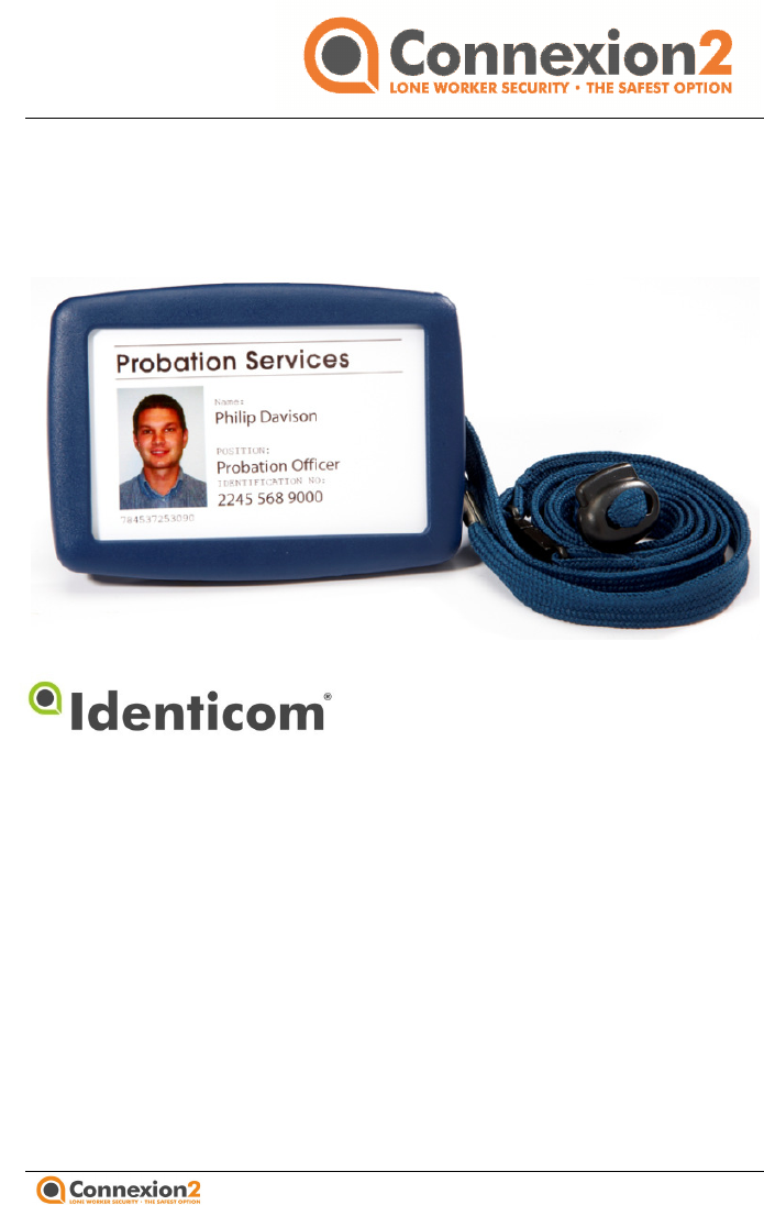
Identicom is a communication device disguised as an ID card
holder. It enables vulnerable solitary workers to communicate
discreetly with their back-up services in potentially hazardous
situations.
About this guide
This user guide provides all the information you need to set up,
operate and take care of your Identicom.
A Technical Reference Manual is available from Connexion2
(please email info@connexion2.com ) which provides
configuration information for the people who deploy and manage
the system, and run the back-up services.

Preface
09/11 page
iv
Identicom Limited Warranty
Thank you for buying this Connexion2 product. Please read this user
manual before attempting to use it. To avoid damaging the Identicom, do
not:
o Expose it to extremes of temperature or humidity;
o Subject it to hard knocks or excessive force;
o Immerse it in liquid; or
o Use volatile or corrosive substances when cleaning it, as damage
caused in any of these ways is not covered by this warranty.
If you have any difficulty using your Identicom, consult the user manual to
check you are using it correctly.
If within 12 months of the date of purchase this Identicom does not
function substantially as described in the user manual because of
defective materials or workmanship, Connexion2 Limited will repair it free
of charge, subject to the following conditions:
Where the fault is the result of misuse, unusual external effects,
accidental damage, normal wear and tear, or unauthorised repair,
Connexion2 Limited may charge you for the repair and retain this
Connexion2 product until you have paid that charge in full.
You must produce proof of purchase, showing the date of purchase of this
Connexion2 product, to have a repair carried out free of charge under this
warranty, so please keep your receipt/invoice safely. To have this
Connexion2 product repaired under this warranty, you first need to
contact Connexion2 via email for a Problem ID Number (Returns
Number). Either return it personally or send it by registered post/Courier,
together with your Problem ID Number, sales receipt, to your Connexion2
supplier or to Connexion2 Ltd, at the address shown in this user manual.
Please ensure that it is properly and securely packed. Please note that we
will not be liable for damage to or loss of this Connexion2 product while it
is in transit to Connexion2 or a Connexion2 supplier; check that your

Preface
09/11 page
v
insurance covers the relevant risks. Service is only available in countries
where Connexion2 Limited officially distributes the product.
In the event of Connexion2 being unable to correct or replace the
Identicom, Connexion2’s liability to you shall not exceed the purchase
price of the Identicom. In no event will Connexion2 be liable for direct,
indirect, special, incidental or consequential loss of profits or loss of data
arising out of use or misuse of the Identicom. Nothing in this warranty
shall limit or restrict Connexion2’s liability for death or personal injury
caused by its negligence.

Preface
09/11 page
vi
Contents
1 Introduction ...................................................................................... 1
2 Initial Setup ....................................................................................... 3
Installing the lanyard or lapel clip .................................................. 4
Inserting the SIM card .................................................................... 5
Inserting your ID card ..................................................................... 7
Charging ......................................................................................... 7
Switching the device on and off ..................................................... 8
Care and maintenance ................................................................... 8
3 Status Checking ................................................................................ 9
Battery and signal status checking ............................................... 10
Ending the status display ............................................................. 10
SIM card faults ............................................................................. 11
Red and Amber Alert status ......................................................... 11
4 Amber Alerts ................................................................................... 12
Starting an Amber Alert ............................................................... 12
Options when in an Amber Alert timer period ............................ 13
5 Red Alerts ....................................................................................... 14
Starting a Red Alert ...................................................................... 14
Voice call connection confirmation .............................................. 16
Heartbeat pulse ............................................................................ 16
Rip Alarm Alerts ........................................................................... 17
Man Down Red Alerts (models i770, i777 and t777 only) ........... 17
Clearing a Red Alert ...................................................................... 19
6 GPS Operation (i757 and i777 only) ............................................... 20
7 GPS Operation (t757 and t777 only) .............................................. 21
8 Identicom Indicators....................................................................... 22
LED indications ............................................................................. 22
Vibration patterns ........................................................................ 24
9 Technical Specifications.................................................................. 26
Preface
09/11 page
vii
Identicom models
This manual covers Identicom models i750, i770, i757 and i777,
and models t757 and t777.
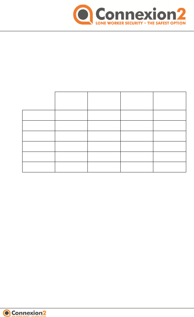
The table below indicates the main distinguishing features of
these models:
GSM GPS* GPS** Man
Down
i750
i770
i757
i777
t757
t777
GSM Global System for Mobile communications
GPS* Global Positioning System – user-initiated location
only; GPS fix transmitted via SMS message at user’s
request or as part of an alert
GPS** Global Positioning System – device tracking, data
logging, and geo-fence information via GPRS
Man Down Ability of the unit to detect when the user is
incapacitated, and alarm appropriately

06/10
1 Introduction
The Identicom has the
appearance of a simple ID card holder. It
holds your ID card, and also discreetly functions as a
communication device to help ensure your personal safety.
In the plastic body behind the ID card, the Identicom contains a
mobile phone, a SIM card and a micro
phone, together with
controls and indicators that allow you to operate the device.
There is also a vibration motor that can indicate confirmation of
your actions by giving recognisable periods of silent vibration.
The organisation that employs you, togethe
r with a service
provider, are responsible for configuring the SIM card in your
Identicom so that it operates in the way best suited to your
needs. This configuration process includes setting up conditions
called “Amber Alerts” and “Red Alerts”, and defini
text messages that will be sent to particular phone numbers in a
specific range of situations.
In this guide, where you see the symbol shown on the left, it
indicates that the mode of operation or feature being described is
configurable; that
is, it may or may not have been enabled on
your device. Check with your manager, or the supplier of your
Identicom, for details of how your unit has been configured.
The main functions of the Identicom are:
•
Before entering a potentially dangerous situation
check the Identicom’s battery level and the signal strength
(to make sure that it will be able to operate effectively if
needed).
• You can start an Amber Alert before you
begin
This sends standard text messages, allows you to send a
brief voice message, and can alert
your back
check your situation if you haven’t cancelled the Amber
Alert within a set time.
• You can start a Red Alert
state with a discreet press of
button while you are in a hazardous situation, or at any
1 Introduction
page
1
appearance of a simple ID card holder. It
holds your ID card, and also discreetly functions as a
communication device to help ensure your personal safety.
In the plastic body behind the ID card, the Identicom contains a
phone, together with
controls and indicators that allow you to operate the device.
There is also a vibration motor that can indicate confirmation of
your actions by giving recognisable periods of silent vibration.
r with a service
provider, are responsible for configuring the SIM card in your
Identicom so that it operates in the way best suited to your
needs. This configuration process includes setting up conditions
called “Amber Alerts” and “Red Alerts”, and defini
ng standard
text messages that will be sent to particular phone numbers in a
In this guide, where you see the symbol shown on the left, it
indicates that the mode of operation or feature being described is
is, it may or may not have been enabled on
your device. Check with your manager, or the supplier of your
Identicom, for details of how your unit has been configured.
Before entering a potentially dangerous situation
, you can
check the Identicom’s battery level and the signal strength
(to make sure that it will be able to operate effectively if
begin
every visit.
This sends standard text messages, allows you to send a
your back
-up services to
check your situation if you haven’t cancelled the Amber
state with a discreet press of
a
button while you are in a hazardous situation, or at any
1 Introduction
09/11 page
2
time when required. This sends standard text messages to
the designated phone numbers, and also opens a voice
link to allow the call centre to hear.
• Identicom models with the Man Down functionality
(models i770 and i777) can automatically initiate a Red
Alert state if the unit detects symptoms that suggest that
the user has become incapacitated. (These symptoms are
configurable to suit each user’s needs.) The user can be
warned by a Pre-Alert vibration (and optionally a call to
the user’s mobile phone) before the Red Alert is initiated.
• Identicom models i757 and i777 have an integrated Global
Positioning System (GPS) to assist with determining your
exact location in the event of an incident.
• Identicom models t757 and t777 have advanced GPS
facilities that allow high frequency logging of GPS data,
uploading of the data log via GPRS, and geo-fencing
facilities for defined locations.
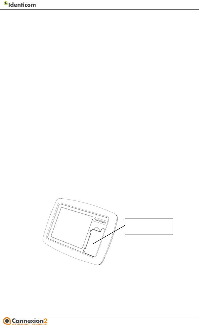
The front of the Identicom is shown below. With no ID card in
place, you can see the door to the recess where the SIM card is
installed.
SIM card door
2 Initial Setup
09/11 page
3
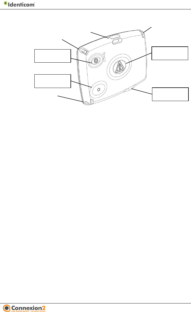
The rear of the Identicom is shown below.
You can attach the lanyard at points A and B for a landscape ID
card, or at points A and C for a portrait ID card. Alternatively, you
can attach a lapel clip at point D instead of the lanyard.
The Status button allows you to check the status of the battery
and the phone signal strength, and to check whether an Amber or
Red Alert has been started. The status LEDs are visible through
the plastic cover adjacent to the Status button.
Press the Amber Alert button to start or cancel an Amber Alert.
Press the Red Alert button to start or cancel a Red Alert.
2 Initial Setup
This section describes how to prepare the Identicom for use,
covering installation of the lanyard or lapel clip, insertion of the
SIM card, insertion of the ID card, charging, care and
maintenance, and switching the device on and off. The box
containing your Identicom includes the following items:
o The Identicom
o Easy Reference Guide
o Lanyard & three lanyard attachment plugs
o Lapel clip
o Charger (including country adapter)
A
B
C
D
Status button
Amber Alert
button
Red Alert
button
Charging
connection
09/11
Installing the lanyard or lapel clip
You install the lanyard at corners A and B (see the illustration on
the previous page) for a landscape ID card, or at corners A and C
for a portrait ID card. The attachment at corner A is by way
plastic plug which fits tightly in its socket, but which will pull out if
tugged firmly. The Identicom can be configured so that pulling
the lanyard plug out of its socket will cause a Red Alert. This is
designed to help you in case a person tries to
remove the
Identicom from you by force. A Red Alert caused in this manner is
referred to as a Rip Alarm Alert.
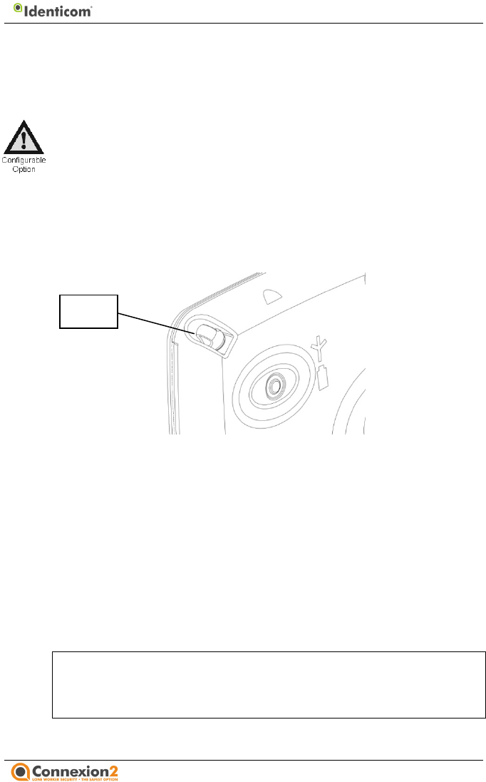
The figure below shows the plug in its socket at corner A.
Three plugs are provided with the Identicom offering increasing
degrees of tightness in the socket. Use the plug
labelled
tightest fitting, which requires the greatest amount of force to
remove it, or the plug labelled 3
for the lightest fitting, which
requires the least amount of force to remove it. We recommend
starting with the middle plug – labelled 2.
If you do not want to use the lanyard, you can attach a lapel clip
at point D (see the illustration on page 2). If yo
u are not using the
lanyard, insert one of the plugs into the socket at corner A to
prevent dust or dirt from entering the socket.
Note:
You must either attach the lanyard, or just insert a
plug, before you attempt to charge or switch on the
Identicom.
Use
the following procedure to attach the lanyard.
Plug
2 Initial Setup
page
4
You install the lanyard at corners A and B (see the illustration on
the previous page) for a landscape ID card, or at corners A and C
for a portrait ID card. The attachment at corner A is by way
of a
plastic plug which fits tightly in its socket, but which will pull out if
tugged firmly. The Identicom can be configured so that pulling
the lanyard plug out of its socket will cause a Red Alert. This is
remove the
Identicom from you by force. A Red Alert caused in this manner is
The figure below shows the plug in its socket at corner A.
Three plugs are provided with the Identicom offering increasing
labelled
1 for the
tightest fitting, which requires the greatest amount of force to
for the lightest fitting, which
requires the least amount of force to remove it. We recommend
If you do not want to use the lanyard, you can attach a lapel clip
u are not using the
lanyard, insert one of the plugs into the socket at corner A to
You must either attach the lanyard, or just insert a
plug, before you attempt to charge or switch on the
the following procedure to attach the lanyard.
2 Initial Setup
09/11 page
5
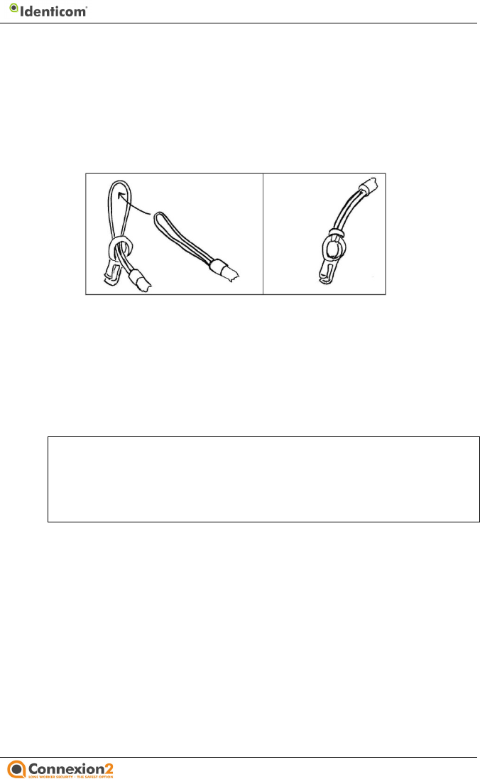
1. Thread the fine loop at one end of the lanyard part way
through the attachment hole in the plug you have selected to
use.
2. Thread the other end of the lanyard through the loop of cord
that has passed through the hole in the plug. Pull the lanyard
tight, so that the loop of cord is snug around the plastic plug.
3. Repeat this procedure with the other end of the lanyard at
the chosen attachment point (B for landscape or C for
portrait). Pull the lanyard tight, so that the loop of cord is
snug around the attachment point.
4. Insert the plastic plug into its socket at corner A. The lanyard
is now attached.
Note: There is no Rip Alarm switch at the lapel clip
attachment point. The Rip Alarm function can be
enabled with the lapel clip by using the lapel clip
lanyard accessory sold separately.
Inserting the SIM card
SIM card configuration is carried out by your employer, working
in conjunction with the service provider. The SIM card is normally
pre-configured so that you can use the Identicom immediately.
If your ID card is already fitted into the Identicom, you must
remove it to get access to the SIM card door. Gently press down
on the edge of the ID card nearest the exit slot, then slide the ID
card out.
Use the following procedure to insert the SIM card.
2 Initial Setup
09/11 page
6
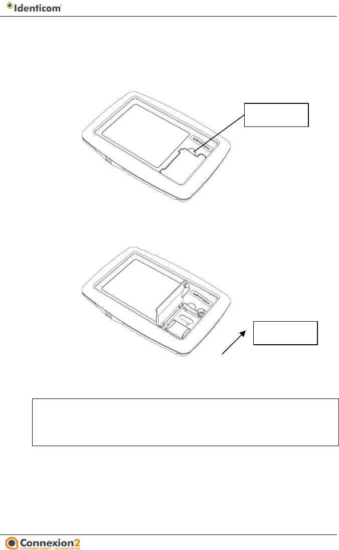
1. Make sure the device is switched off before inserting or
removing a SIM card. Use a finger nail, a small screwdriver tip
or a nail file to prise up the SIM card door next to the
rounded corner.
2. With the SIM card door open, raise the SIM card holder by
sliding the catch mechanism towards the Identicom logo.
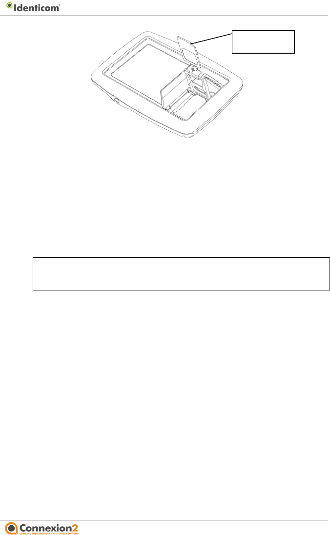
3. With the SIM card holder raised, orientate the SIM card as
shown and insert it in the holder.
Note: The gold connector must be on the under side, and the
angled corner must be next to the bottom right corner of
the device (looking at the front).
Prise open
here
Slide catch to
raise holder
2 Initial Setup
09/11 page
7
4. Press down the card holder and slide the catch mechanism
away from the Identicom logo to secure the SIM card in
place.
5. Close the SIM card door by pressing down on the rounded
corner.
The Identicom is now ready for use, but you should always charge
the device before using it.
Note: You must insert a valid SIM card to be able to use the
unit.
Inserting your ID card
Fit your ID card into the slot at the right side of the Identicom (as
you look at the front) and slide it in until it clicks into place. To
remove your card, gently press down on the edge of the ID card
nearest the exit slot, then slide the card out.
Charging
The Identicom must be fully charged before you attempt to use it,
in order to condition the battery fully. We recommend leaving
the device on charge for a minimum of 6 hours.
To make sure that the battery is fully charged when you need to
use the Identicom, always charge the device in between uses.
SIM card
angled corner

2 Initial Setup
09/11 page
8
To charge the Identicom, plug in and switch on the charger, then
connect the charging cable to the Identicom charge connection
point (see the illustration on page 2).
When the Identicom is connected to the charger, the Battery LED
is active. (The Battery LED is on the back of the device, next to the
Status button.) As the battery charges, the LED changes from
flashing red, to flashing amber, and when the battery is fully
charged, to constant green. If the battery LED remains red for a
long period, the Identicom requires a service.
Note: Placing the Identicom “on charge” automatically
switches the device on. When taken off charge, the
device remains switched on and ready to use.
Switching the device on and off
• To check the Identicom is on, press the Status button for 2
seconds. If the LEDs do not start flashing, the Identicom is
off.
• To switch the Identicom on, press the Status and Amber
buttons together until the LEDs start flashing. The device
vibrates briefly to confirm.
• To switch the Identicom off, press the Status and Amber
buttons together until the device vibrates twice.
When the Identicom is on, it registers with the mobile phone
network and is ready to communicate an Amber or Red alert. If
you go out of coverage for more than 30 minutes, the Identicom
switches to a sleep mode to preserve battery power. This does
not stop the Identicom from working, but when you press any of
the buttons it will take slightly longer to connect the call or report
the status.
Care and maintenance
The Identicom is purposely designed so that you do not need to
perform any routine maintenance procedures. However, you
should note the following points about cleaning and general care.

09/11
Cleaning
Use a damp cloth (not wet) to remove any dirt from the
Identicom. Be very careful not to allow water into the unit,
particularly around the SIM card door.
Do not use any alcohol or chemical cleaning agents of
Moisture resistance
The Identicom is not waterproof and you should take care not to
expose the unit to liquids of any kind, including water, rain, and
extreme humidity.
Impact damage
The Identicom is made from a tough ABS plastic case. It is
des
igned to resist a certain amount of damage caused by general
use, but will not withstand heavy impacts.
Removal of SIM cards
If the SIM card needs to be removed from the device the unit
MUST be turned off. Do not
remove the SIM whilst the unit is
turned on or whilst
on charge, as this will cause the unit not to
function.
3 Status Checking
You can check the Identicom’s battery level and the phone signal
strength before a visit, so that you can make sure that it will be
able to operate effectively if needed
. Your Identicom can be
configured so that this status information is also sent as a text
message to your administrator or monitoring centre.
3 Status Checking
page
9
Use a damp cloth (not wet) to remove any dirt from the
Identicom. Be very careful not to allow water into the unit,
Do not use any alcohol or chemical cleaning agents of
any type.
The Identicom is not waterproof and you should take care not to
expose the unit to liquids of any kind, including water, rain, and
The Identicom is made from a tough ABS plastic case. It is
igned to resist a certain amount of damage caused by general
If the SIM card needs to be removed from the device the unit
remove the SIM whilst the unit is
on charge, as this will cause the unit not to
You can check the Identicom’s battery level and the phone signal
strength before a visit, so that you can make sure that it will be
. Your Identicom can be
configured so that this status information is also sent as a text
message to your administrator or monitoring centre.
09/11
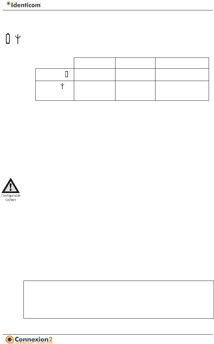
Battery and signal status checking
Press and hold the Status
button until both the LEDs start to flash
red. Af
ter a short while, the battery and signal LEDs stop flashing
to indicate the following:
Green Amber
Red
Battery Good Low
Poor
Signal Good Low
Poor or no
network signal
If either LED is red, you should not rely on the Identicom in an
emergency.
When the battery LED is Amber, you should recharge the
Identicom as soon as possible.
Refer to the Technical Specifications in section 9 of this guide for
expected battery life, when charged.
Identicom offers the facility of using vibration patterns to in
activation of the Status Check and to confirm that neither the
network coverage nor battery strength LED is red. This function
aids the use of Identicom by the visually impaired. The vibration
patterns are described in the table in Section 8 of this
There is another configurable option
to display the current GPS
location fix status at the end of a Status Check. See Section 7 of
this guide for further details.
Ending the status display
When both the status LEDs have displayed their status for 5
seconds, the LEDs are turned off and the device is ready for use.
Note:
If you press the status button when the unit is out of
coverage, the status is displayed to you by way of the
LEDs, but the unit waits until it is back in coverage
before attempting t
o send any text messages.
3 Status Checking
page
10
button until both the LEDs start to flash
ter a short while, the battery and signal LEDs stop flashing
Red
Poor
Poor or no
network signal
If either LED is red, you should not rely on the Identicom in an
When the battery LED is Amber, you should recharge the
Refer to the Technical Specifications in section 9 of this guide for
Identicom offers the facility of using vibration patterns to in
dicate
activation of the Status Check and to confirm that neither the
network coverage nor battery strength LED is red. This function
aids the use of Identicom by the visually impaired. The vibration
patterns are described in the table in Section 8 of this
guide.
to display the current GPS
location fix status at the end of a Status Check. See Section 7 of
When both the status LEDs have displayed their status for 5
seconds, the LEDs are turned off and the device is ready for use.
If you press the status button when the unit is out of
coverage, the status is displayed to you by way of the
LEDs, but the unit waits until it is back in coverage
o send any text messages.

3 Status Checking
09/11 page
11
SIM card faults
If no SIM card is fitted, or there is a fault with the SIM card, the
Identicom flashes the battery and signal LEDs red alternately for
two seconds, and then switches itself into the ‘power off’ state.
You must insert a valid SIM card to be able to use the unit.
Red and Amber Alert status
If the Identicom is in an Amber Alert state or a Red Alert state
when the Status button is pressed, the signal status LED shows a
two second constant indication of the state:
• Constant amber for two seconds indicates an Amber Alert
is in progress.
• Constant red for two seconds indicates a Red Alert is in
progress.

09/11
4 Amber Alerts
An Ambe
r Alert is an advance warning to your back
that you are about to enter a potentially dangerous situation.
Typically, you would start an Amber Alert before you enter the
situation, such as in the street or your car before entering a
house. This
gives you the privacy to send a brief voice message
describing the situation and/or details of your location.
Your Identicom can be configured so that the Amber Alert lasts
for a set period. If you take no action at the end of this Amber
Alert period, the
device automatically escalates into a Red Alert
to advise your back-
up services that a problem has been
encountered.
Most of the options described below for Amber Alerts are
configurable. Check with your manager, or the supplier of your
Identicom, for det
ails of how your unit has been configured.
Starting an Amber Alert
Press the Amber Alert
button for at least 1.5 seconds to start an
Amber Alert. The Identicom gives three short bursts of vibration
to confirm the state. If configured, the Amber Alert text
is sent to the designated numbers.
If configured, the Identicom also opens a voice call to the
designated number, so that you can send a voice message to
describe the situation. The Signal and Battery LEDs show constant
amber while the call is bein
g connected, and then turn to flashing
amber when the connection has been made.
The flashing amber
LEDs are the prompt to start the voice message. There is also the
option of having the device vibrate once when the LEDs switch
from constant to flashing as
an aid for the visually impaired.
The time allowed for you to send the voice message can be set
between 1 and 60 seconds. Ten seconds before the end of this
call period, the LEDs change back to constant amber to warn you
that the call period is soon ending
. When the voice call period
ends, the Signal and Battery LEDs go out.
There is the option of
4 Amber Alerts
page
12
r Alert is an advance warning to your back
-up services
that you are about to enter a potentially dangerous situation.
Typically, you would start an Amber Alert before you enter the
situation, such as in the street or your car before entering a
gives you the privacy to send a brief voice message
describing the situation and/or details of your location.
Your Identicom can be configured so that the Amber Alert lasts
for a set period. If you take no action at the end of this Amber
device automatically escalates into a Red Alert
up services that a problem has been
Most of the options described below for Amber Alerts are
configurable. Check with your manager, or the supplier of your
ails of how your unit has been configured.
button for at least 1.5 seconds to start an
Amber Alert. The Identicom gives three short bursts of vibration
to confirm the state. If configured, the Amber Alert text
message
If configured, the Identicom also opens a voice call to the
designated number, so that you can send a voice message to
describe the situation. The Signal and Battery LEDs show constant
g connected, and then turn to flashing
The flashing amber
LEDs are the prompt to start the voice message. There is also the
option of having the device vibrate once when the LEDs switch
an aid for the visually impaired.
The time allowed for you to send the voice message can be set
between 1 and 60 seconds. Ten seconds before the end of this
call period, the LEDs change back to constant amber to warn you
. When the voice call period
There is the option of

4 Amber Alerts
09/11 page
13
having a timer period initiated after the voice call period ends.
This is detailed later in this section.
When you start the Amber Alert, the Identicom attempts to dial,
to allow your voice message to be left. If the voice call cannot be
connected, it will retry connecting the call the configured number
of times (between 0 and 9).
The length of time allowed for an Amber Alert Timer period,
initiated after the voice call period ends, can be configured for
each Identicom to be anything between 1 and 120 minutes.
If you press the Status button during an Amber Alert Timer
period, the Signal status LED shows amber to confirm the Amber
Alert state.
At the end of the Amber Alert Timer period, the Identicom gives
five long bursts of vibration to remind you to take some action.
(This vibration pattern can also be configured for the number of
bursts and duration per burst.) There is then a one minute period
for you to decide what action to take. The options at the end of
this Amber Alert Timer period are explained in the next section.
Your Identicom can be configured to use Amber Alerts without
any timer period. In this mode of operation, there is no automatic
escalation from Amber Alert to Red Alert.
Options when in an Amber Alert timer period
Your options when in an Amber Alert Timer period are to cancel
it, to extend the period, or to allow it to escalate into a Red Alert.
• You can press the Amber Alert button for more than 1.5
seconds to cancel the Amber Alert Timer period. This
signifies that the potential danger did not arise, or that
you are now away from the hazardous situation. The
Identicom signals confirmation by giving two short
vibrations. The pre-configured Amber Alert Cancelled text
message is sent to the designated numbers.

09/11
• You can press the Amber Alert
button for less than 1.5
seconds to extend the Amber Alert Timer
period. The
duration of the extension is configurable between 1 and
60 minutes. The Identicom gives
a short burst of vibration
to confirm the extension. The end of the extension period
is signalled in the same way as the original Amber Alert
Timer
period, and you can continue to extend repeatedly,
for as long as you need. Y
our Identicom can also be
confi
gured to send a text message when you choose to
extend the Amber Alert Timer period.
• If you do nothing when the Amber Alert
Timer
ends, the implication is that you were not able to take any
action, the Identicom enters the Red Alert state. (This is
described in Section 5 of this guide.)
You do not have to wait for the signalled end of the Amber Alert
Timer
period to cancel it or extend it. Pressing the
button for more or less than 1.5 seconds at any time during the
Amber Alert Timer period will cancel or extend the period, as
described above.
5 Red Alerts
A Red Alert is an emergency state. It is not necessarily a violent
situation: it could be a case of
verbal abuse which you want your
back-up services to listen to and record.
Note:
The legality of recording such events varies from
country to country. Please check with your service
provider.
Most of the options described below for Red Alerts are
configu
rable. Check with your manager, or the supplier of your
Identicom, for details of how your unit has been configured.
Starting a Red Alert
There are four ways of starting a Red Alert:
5 Red Alerts
page
14
button for less than 1.5
period. The
duration of the extension is configurable between 1 and
a short burst of vibration
to confirm the extension. The end of the extension period
is signalled in the same way as the original Amber Alert
period, and you can continue to extend repeatedly,
our Identicom can also be
gured to send a text message when you choose to
Timer
period
ends, the implication is that you were not able to take any
action, the Identicom enters the Red Alert state. (This is
You do not have to wait for the signalled end of the Amber Alert
period to cancel it or extend it. Pressing the
Amber Alert
button for more or less than 1.5 seconds at any time during the
Amber Alert Timer period will cancel or extend the period, as
A Red Alert is an emergency state. It is not necessarily a violent
verbal abuse which you want your
The legality of recording such events varies from
country to country. Please check with your service
Most of the options described below for Red Alerts are
rable. Check with your manager, or the supplier of your
Identicom, for details of how your unit has been configured.

5 Red Alerts
09/11 page
15
• Press the Red Alert button for more than 2.5 seconds (the
unit will vibrate) followed by a second press of the Red
Alert button to activate the call (within 15 seconds). If you
don’t press the button again within 15 seconds the unit
will vibrate to inform you that Red Alert did not occur.
If configured without double button press, simply
press the Red Alert button for more than 2.5
seconds. The duration of the press of the Red
Alert button to activate Red Alerts can be pre-
configured between 0.2 and 3 seconds.
• Allow an Amber Alert Timer period to expire and escalate
into a Red Alert.
• If your Identicom is configured to do so, and your lanyard
is fitted, forcible removal of the lanyard plug will also start
a Red Alert. This type of Red Alert is also referred to as a
Rip Alarm Alert.
• For models i770, i777 and t777 with the Man Down
function, the unit can detect symptoms that suggest that
you have become incapacitated. (These symptoms are
configurable to suit each user’s needs.) You are warned by
a Pre-Alert vibration (and optionally a call to your mobile
phone) before the Red Alert is initiated.
When a Red Alert is started, the Identicom gives three short
bursts of vibration to confirm the state. The Identicom opens a
voice call to the designated number and enables the microphone,
so that your back-up services can listen to and/or record the
situation. Also, the pre-configured Red Alert text messages are
sent to the designated numbers. Your Identicom can be
configured to send different messages to the primary and
secondary telephone numbers.

5 Red Alerts
09/11 page
16
Caution: The three bursts of vibration confirm the start of the
Red Alert period, but there is normally a brief delay
while the mobile phone network makes the
connection. This can take several seconds, so do not
assume that everything is being recorded from the
point where the three bursts of vibration are made.
If you initiate a Red Alert when your unit is out of coverage, the
Identicom will not be able to send the Red Alert messages, so it
gives a single long vibration pulse instead of the three short
pulses. This indicates that the Red Alert has not been successfully
transmitted.
When a Red Alert is started, the Identicom attempts to dial the
voice call number. If the voice call cannot be connected, it will
retry connecting the call the configured number of times
(between 0 and 9). Your Identicom can also be configured to keep
trying to make the voice call connection continuously, with no
limit to the number of retries.
The call length of a Red Alert can be configured for each
Identicom to be anything between 1 and 120 minutes. The Red
Alert ends only when it is cleared by you, or, if your Identicom is
configured to do so, remotely by your service provider.
Voice call connection confirmation
Your Identicom can be configured to give a confirmation buzz (5
short buzzes) when a voice call connection is successfully made
by your monitoring service. This is designed to give reassurance
that the Red Alert situation is now being monitored.
Heartbeat pulse
During an active Red Alert call, your Identicom can be configured
so that it will periodically vibrate like a heartbeat (two short
pulses, repeated – the repeat time is configurable). This is to
provide reassurance to you that the call is active and open, and
that someone is listening to and/or recording events.
09/11
In a Man Down Red Alert (models i770 and i777 only), the
heartbeat functio
n delivers three short pulses rather than two, to
enable the monitoring service to distinguish the type of Red Alert.
Rip Alarm Alerts
If your lanyard is fitted (see Section 2 of this guide), your
Identicom can be configured to enable Rip Alarm Alerts. The
occur if the lanyard plug is forcibly removed from its socket
such as if someone tries to take the device from you. Once
started, a Rip Alarm Alert is handled in exactly the same way as
any other Red Alert.
Note:
Rip Alarm Alerts cannot be triggered b
unless the lapel clip lanyard accessory is utilised.
Man Down Red Alerts (models i770, i777 and t777 only)
The way in which the Man Down
functionality can detect
symptoms that suggest that you have become incapacitated can
be configured to
take account of the type of work you do, and the
risks you may encounter.
The Man Down
detection features are configurable. Check with
your manager, or the supplier of your Identicom, for details of
how your unit has been configured.
There are three aspe
cts of Man Down detection that can be
configured:
1.
Change in orientation. The unit detects a change in angle
from the vertical (a degree of tilt) and measures the period
for which the tilt continues. For example, if your working
habits are such that you
(and your Identicom) are normally
upright, and you have a fall or are knocked over, the unit
could detect if you remain in a horizontal position.
2. Period of non-
movement. The unit has a movement sensor
and a threshold time value can be set so that the un
when you have remained immobile for longer than this time.
The unit can be configured so that a Man Down alert is raised
5 Red Alerts
page
17
In a Man Down Red Alert (models i770 and i777 only), the
n delivers three short pulses rather than two, to
enable the monitoring service to distinguish the type of Red Alert.
If your lanyard is fitted (see Section 2 of this guide), your
Identicom can be configured to enable Rip Alarm Alerts. The
se
occur if the lanyard plug is forcibly removed from its socket
–
such as if someone tries to take the device from you. Once
started, a Rip Alarm Alert is handled in exactly the same way as
Rip Alarm Alerts cannot be triggered b
y the lapel clip
unless the lapel clip lanyard accessory is utilised.
functionality can detect
symptoms that suggest that you have become incapacitated can
take account of the type of work you do, and the
detection features are configurable. Check with
your manager, or the supplier of your Identicom, for details of
cts of Man Down detection that can be
Change in orientation. The unit detects a change in angle
from the vertical (a degree of tilt) and measures the period
for which the tilt continues. For example, if your working
(and your Identicom) are normally
upright, and you have a fall or are knocked over, the unit
could detect if you remain in a horizontal position.
movement. The unit has a movement sensor
and a threshold time value can be set so that the un
it detects
when you have remained immobile for longer than this time.
The unit can be configured so that a Man Down alert is raised

5 Red Alerts
09/11 page
18
when either a Change in orientation or a Period of non-
movement is detected, or so that a Man Down alert is raised
only when both conditions are detected.
3. Sudden, rapid movement. The unit’s movement sensor can
detect a sudden, rapid movement, such as might be caused
by an impact, or being knocked over. The unit can also be
configured so that the period of non-movement is much
shorter following a detected impact than it would be under
normal circumstances. For example, the period of non-
movement could be set at three minutes before an alarm
was raised in normal circumstances, but this could be
reduced to 30 seconds of non-movement in the event of a
sudden impact.
Your employer will have determined the most appropriate
settings for configuring your device.
Man Down detection can be configured so that it is active at all
times, or so that it is active only when you are in an Amber Alert
state, and the Amber Alert timer is running.
Man Down detection is always disabled when the unit is on its
charger, or switched off.
Man Down Pre-Alert
To avoid raising a Man Down Red Alert simply because of a
naturally occurring period of non-movement, or change in
orientation, the device can be configured to enter a Pre-Alert
period before initiating the Red Alert. If the device detects what
could be a Man Down situation (based on your configured
profile), it will first raise a Pre-Alert. The Pre-Alert period can be
configured for any time up to four minutes. During this period,
the Identicom will attempt to alert you to the imminent Man
Down condition by means of a vibration pattern, and (if
configured) by calling your mobile phone. Any movement of the
Identicom will cancel the Man Down condition, as it can now
detect that you are capable of normal movement.

5 Red Alerts
09/11 page
19
If you do not cancel the Man Down condition (by moving your
Identicom), a Man Down Red Alert will be raised at the end of the
Pre-Alert period.
During a Man Down Red Alert, the Heartbeat function repeatedly
vibrates with three short pulses, repeated every defined period
(the repeat time is configurable) to provide reassurance to you
that the call is active and open. You can clear a Man Down Red
Alert in the same way as any other Red Alert (see below).
Clearing a Red Alert
Press the Red Alert button for more than 1.5 seconds to clear the
alert. The duration of the press of the Red Alert button to
deactivate Red Alerts can be pre-configured between 0.2 and 3
seconds.
This signifies that the dangerous situation has eased. The
Identicom signals confirmation by giving two short vibrations. The
pre-configured Red Alert Cleared text messages are sent to the
designated numbers. Also, the voice call link is terminated. Your
Identicom can be configured to send different messages to the
primary and secondary telephone numbers.
There are two ways that your Identicom can be configured to
clear Red Alerts:
• A Red Alert can be cleared only by you pressing the Red
Alert button for more than 1.5 seconds.
• A Red Alert can be cleared either by you pressing the Red
Alert button for more than 1.5 seconds, or remotely by
the service provider terminating the call.
Your managers or the service providers will be able to tell you
how your Identicom is configured.
To cancel a Rip Alarm Alert, you must first re-insert the lanyard
plug, and then press the Red Alert button for more than 1.5
seconds. This applies whether it was a genuine Rip Alarm, or
whether the lanyard was detached accidentally.

6 GPS Operation (i757 and i777 only)
09/11
6 GPS Operation (i757 and i777 only)
Identicom models i757 and i777 can be configured so that a GPS
location request is made in any or all of the following situations:
•
When you press any of the Identicom buttons
• When you check the statu
s of your Identicom
• When you enter an Amber Alert state
• When you enter a Red Alert state
The GPS operation features are configurable. Check with your
manager, or the supplier of your Identicom, for details of how
your unit has been configured.
In the even
t of a serious incident, transmission of your exact
location coordinates will help to ensure a speedier response in
sending you assistance.
6 GPS Operation (i757 and i777 only)
page
20
Identicom models i757 and i777 can be configured so that a GPS
location request is made in any or all of the following situations:
When you press any of the Identicom buttons
s of your Identicom
The GPS operation features are configurable. Check with your
manager, or the supplier of your Identicom, for details of how
t of a serious incident, transmission of your exact
location coordinates will help to ensure a speedier response in

7 GPS Operation (t757 and t777 only)
09/11
7 GPS Operation (t757 and t777 only)
Identicom models t757 and t777 can be configured so that GPS
location informati
on is logged at a much higher frequency than is
possible with the i-
series Identicoms, and is transmitted via GPRS
to the monitoring service.
Standard GPS operation is still available (as in the i
but GPRS communication is faster, more relia
ble and offers
further benefits:
• Using GPS data for device tracking
• Uploading the data log via GPRS
•
Detecting when the device enters or exits a geo
zone. (Up to 100 such zones can be defined.)
The advanced GPS operation features are configurable.
with your manager, or the supplier of your Identicom, for details
of how your unit has been configured.
One of the configurable options is to display the current GPS
location fix status at the end of a Status Check. If configured, the
Signal LED fla
shes blue for up to two minutes if the device is
searching for a GPS fix, and displays a steady blue for five seconds
if the
latest GPS location fix gave a valid location. The steady blue
“valid GPS fix” indication can be accompanied by a single short
vibration, if required.
You should always perform a status check and get a GPS location
fix after turning your Identicom on or moving outside from
indoors.
GPS requires a clear line of site to the sky, not obstructed by
buildings or other obstacles. The GPS location
operation
work whilst the unit is indoors.
7 GPS Operation (t757 and t777 only)
page
21
Identicom models t757 and t777 can be configured so that GPS
on is logged at a much higher frequency than is
series Identicoms, and is transmitted via GPRS
Standard GPS operation is still available (as in the i
-series units),
ble and offers
Detecting when the device enters or exits a geo
-fence
zone. (Up to 100 such zones can be defined.)
The advanced GPS operation features are configurable.
Check
with your manager, or the supplier of your Identicom, for details
One of the configurable options is to display the current GPS
location fix status at the end of a Status Check. If configured, the
shes blue for up to two minutes if the device is
searching for a GPS fix, and displays a steady blue for five seconds
latest GPS location fix gave a valid location. The steady blue
“valid GPS fix” indication can be accompanied by a single short
You should always perform a status check and get a GPS location
fix after turning your Identicom on or moving outside from
GPS requires a clear line of site to the sky, not obstructed by
operation
will not
8 Identicom Indicators
09/11 page
22
8 Identicom Indicators
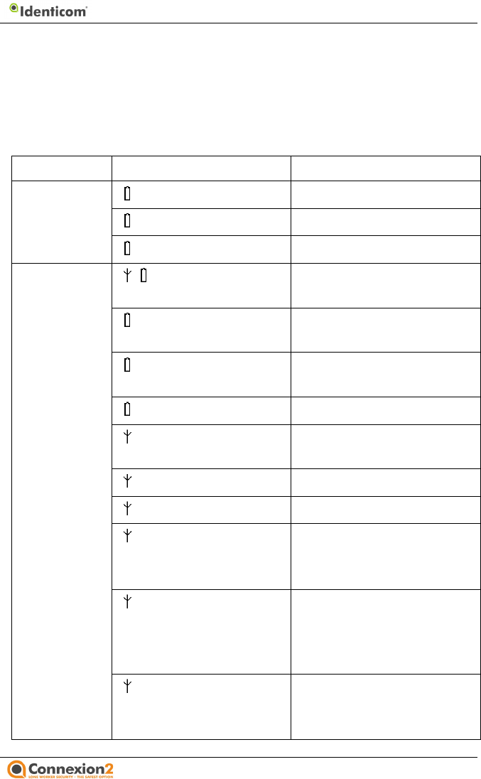
The following tables summarise the indications given by Identicom, both
by the LEDs and by the different patterns of vibration.
LED indications
Device state LED / colour / condition Meaning
On charge Red, flashing Trickle charging
Amber, flashing Charging
Green, constant Charging complete
Status
checking
Red, flashing Indicates start of status
display
Red, constant Battery condition bad, or
no status sent
Amber, constant Battery condition below
70%
Green, constant Battery condition good
Red, constant Signal quality bad, or no
status sent
Amber, constant Signal quality average
Green, constant Signal quality good
Amber constant for 2
seconds when Status
button pressed
An Amber Alert is in
progress
Red constant for 2
seconds
when Status button
pressed
A Red Alert is in progress
Blue flashing for up to
2 minutes, at end of
status check
Searching for a valid GPS
location fix

8 Identicom Indicators
09/11 page
23
Device state LED / colour / condition Meaning
Blue constant for 5
seconds
A valid GPS location fix was
found
Amber Alert Amber, constant Call being connected, then
last 10 seconds of call
period
Amber, flashing Call connected (until last
10 seconds)
At power on Red, flashing
alternately for 2 seconds,
then power off
SIM card fault, or no SIM
card present

09/11
Vibration patterns
Some of the vibration patterns described below are configurable.
Check with your manager, or the supplier of your Identicom, for
details of how your unit has been configured.
Identicom Action
Vibration pattern
Confirmation of switch to Power Off mode
Two short pulses
Confirmation of switch to Power On mode
Single short pulse
Confirmation of start of Amber or Red Alert
Three short pulses
End of Amber Alert period – action required
or a Red Alert will follow
Five long pulses
Red Alert requested but out of coverage –
unable to send messages
Single long pulse
Confirmation of extension of Amber Alert
period
Single short pulse
Confirmation of termination of Amber Alert
Two short pulses
‘Heartbeat’ confirmation of Red Alert call
still active
Two short pulses
configured interval)
‘Heartbeat’ confirmation of Man Down Red
Alert call still active
Three short pulses
configured interval)
Confirmation that a voice call connection has
been made
Five short pulses
Man Down Pre-Alert warning
Continual long pulses
for the duration of the
Pre-
Alert period
Confirmation of start of Status Check (if this
vibration function is enabled on the Status
Check) *
Three short pulses
Confirmation that neither the network
coverage or battery strength are red (if this
vibration function is enabled on the Status
Check) *
Single short pulse
8 Identicom Indicators
page
24
Some of the vibration patterns described below are configurable.
Check with your manager, or the supplier of your Identicom, for
Vibration pattern
Two short pulses
Single short pulse
Three short pulses
Five long pulses
Single long pulse
Single short pulse
Two short pulses
Two short pulses
(at
configured interval)
Three short pulses
(at
configured interval)
Five short pulses
Continual long pulses
for the duration of the
Alert period
Three short pulses
Single short pulse

8 Identicom Indicators
09/11 page
25
Confirmation that the latest GPS location fix
gave a valid location (if this vibration
function is enabled on the Status Check) *
Single short pulse
Confirmation to commence voice message
on Amber Alert (if this vibration function is
enabled on Amber Alerts) *
Single short pulse
Confirmation of termination of Red Alert Two short pulses
* Identicom offers the facility of using vibration patterns to
indicate activation of the Status Check, confirmation that
neither the network coverage nor battery strength LED is
red, and confirmation that a valid GPS location fix was
obtained. This function aids the use of Identicom by the
visually impaired.

9 Technical Specifications
09/11 page
26
9 Technical Specifications
Dimensions 102 x 72 x 12 mm
Overall weight Identicom i750 & i770 78 g
(approx., including lanyard).
Identicom i757 & i777 85g
(approx., including lanyard)
Identicom t757 & t777 85g
(approx., including lanyard)
Operating temperature
range
-10°C to +40°C
Operating humidity
range
0-95% non-condensing
Communication system Quad-band GSM
GSM frequency – Quad-
band
850 MHz, 900 MHz, 1800 MHz
and1900 MHz
Battery life – standby 60 hours (estimated)
GPS Units: 24 hours (estimated)
Battery life – talk time 2.5 hours (estimated)
Case ABS plastic
CE Marking The product is designed to conform
with this specification wherever
possible and applicable, and is CE
marked.
EN55022 Emissions and
susceptibility
The product is designed to conform
with this specification wherever
possible and applicable.
EEC Low voltage
Directive
The product is designed to conform
with this specification wherever
possible and applicable.
SAR level (see below) Maximum 1.43 W/kg (t777)
Maximum 1.29 W/kg (i770)

9 Technical Specifications
09/11 page
27
FCC ID i770: VTJS10611
t777: VTJS10621
Industry Canada i770: 7467A-S10611
t777: 7467A-S10621
Specific Absorption Rate (SAR)
The Identicom, as for all Global System Mobile communication
(GSM) based products, emits low frequency signals in the form of
Radio Frequency Electromagnetic Energy (RFEE). The absorption
of RFEE is measured by the Specific Absorption Rate (SAR) in units
of Watts per kilogram (W/kg). It is defined as the rate at which
RFEE is absorbed per unit mass of a biological body.
The maximum SAR value for a model t777 Identicom is 1.43
W/kg. The maximum SAR value for a model i770 Identicom is 1.29
W/kg. The European R&TTE Directive quotes a maximum SAR
value of 2 W/kg. This value includes a substantial margin of
safety. The Identicoms are therefore below this limit and actual
Identicom SAR values during normal operation are often below
their 1.43 W/kg and 1.29 W/kg maximum stated values.
Risks associated with pacemakers
Due to the maximum SAR values of 1.43 W/kg and 1.29 W/kg,
Identicom should not impair the performance of implanted
pacemakers. However, the general recommendation is to
maintain at least 15 centimetres between a GSM-based device
and a pacemaker. If you are in any doubt, seek advice and
clarification from your physician and/or the manufacturer of your
specific pacemaker.
Use of Identicom in restricted areas
Use of Identicom, as with mobile phones, should be in
accordance with regulations, protocols and stipulations relating
to the specific environment. Where the use of mobile phones is
prohibited, the Identicom should be turned off. There may be

9 Technical Specifications
09/11 page
28
risks associated with interference with equipment sensitive to
RFEE (such as aircraft, hospitals and healthcare facilities) or
potentially explosive environments (such as petrol stations and
chemical plants).
Disposal and recycling information
This product must not be disposed of as unsorted municipal
waste. Please dispose of this product in accordance with local
environmental laws and guidelines, by returning it to your point
of sale or to your municipal collection point for recycling. Note
that this product contains a battery that cannot be removed by
the customer. For advice on disposal, please contact Connexion2.
FCC Compliance Statement and RF Exposure Statement (t777)
The t777 device complies with Part 15 of the FCC Rules.
Operation is subject to the following two conditions:
(1) This device may not cause harmful interference, and
(2) This device must accept any interference received, including
interference that may cause undesired operation.
This equipment complies with FCC RF radiation exposure limits
set forth for an uncontrolled environment. SAR has been
evaluated with a maximum SAR value reported of 1.43W/kg. This
transmitter must not be co-located or operating in conjunction
with any other antenna or transmitter.
FCC Compliance Statement and RF Exposure Statement (i770)
The i770 device complies with Part 15 of the FCC Rules.
Operation is subject to the following two conditions:
(3) This device may not cause harmful interference, and
(4) This device must accept any interference received, including
interference that may cause undesired operation.
This equipment complies with FCC RF radiation exposure limits
set forth for an uncontrolled environment. SAR has been

9 Technical Specifications
09/11 page
29
evaluated with a maximum SAR value reported of 1.29W/kg. This
transmitter must not be co-located or operating in conjunction
with any other antenna or transmitter.
IC Compliance Statement
This device complies with Industry Canada licence-exempt RSS
standard(s). Operation is subject to the following two conditions:
(1) this device may not cause interference, and (2) this device
must accept any interference, including interference that may
cause undesired operation of the device.
Le présent appareil est conforme aux CNR d'Industrie Canada
applicables aux appareils radio exempts de licence. L'exploitation
est autorisée aux deux conditions suivantes : (1) l'appareil ne doit
pas produire de brouillage, et (2) l'utilisateur de l'appareil doit
accepter tout brouillage radioélectrique subi, même si le
brouillage est susceptible d'en compromettre le fonctionnement.
The S10621 has been designed to comply with safety
requirements for exposure to radio waves (SAR). SAR testing has
been performed in accordance with RSS-102, with the S10621
transmitting at its highest certified power level in all used
frequency bands. The highest SAR value for the S10621 when
tested was 1.43W/Kg. Please follow the instructions included in
the user guide for product installation and use.
Le S10621 est conçu pour se conformer aux exigences de sécurité
pour l'exposition aux ondes radio (SAR). Tests SAR a été effectué
conformément à la norme RSS-102, avec le S10621 à son niveau
de puissance maximum certifié dans toutes les bandes de
fréquences utilisées. La valeur SAR maximale pour le S10621
lorsqu'il est testé était 1.43W/Kg. S'il vous plaît suivez les
instructions incluses dans le guide utilisateur pour l'installation du
produit et son utilisation.
Operation is subject to the following two conditions:
(1) this device may not cause interference, and

9 Technical Specifications
09/11 page
30
(2) this device must accept any interference received, including
interference that may cause undesired operation of the
device
Changes or modifications to this unit not expressly approved by
the party responsible for compliance could void the user’s
authority to operate the equipment.