SoloProtect S10977U GSM/GPRS/EDGE/UMTS/HSPA Module User Manual User Guide
SoloProtect Limited GSM/GPRS/EDGE/UMTS/HSPA Module User Guide
Contents
- 1. User Manual
- 2. User Manual Host
User Manual Host

DISTRIBUTION: INTERNAL + SOLOPROTECT CUSTOMERS
User Guide
SoloProtect ID US
16 August 2018
Document Version 2.0
Last Updated: 7 September 2018
SoloProtect Ltd
Suzy Lamplugh House
Vantage Drive
Sheffield, S9 1RG
United Kingdom
Phone: +44 114 399 6000
DISTRIBUTION: INTERNAL + SOLOPROTECT CUSTOMERS
SoloProtect ID US: User Guide
US SoloProtect ID User Guide v2.0 d1909189
© SoloProtect Ltd, 2018 Page II of 31
Document Revision History
Version
Date
Author
Description
1.0
16/August/2018
JW
New Document created – Draft in progress
2.0
7/September/2018
KM
Changes proposed by UL for certification
Contributors
Abbreviation
Name
Position
JW
Jude Wing
Product Support Specialist
KM
Kamlesh Makwana
Quality & Compliance Manager
Document Information
Title
SoloProtect ID User Guide
Project
SoloProtect ID User Guide Update
For
SoloProtect Ltd (“SPUK”)
By (owner)
Jude Wing
Requested By
Nick Davies
Distribution
Internal + SoloProtect Customers
Document ID
US SoloProtect ID User Guide v1.0 d180816
Date Created
16 August 2018
Input Documents
Nil
Reviewers
Nick Davies

DISTRIBUTION: INTERNAL + SOLOPROTECT CUSTOMERS
SoloProtect ID US: User Guide
US SoloProtect ID User Guide v2.0 d1909189
© SoloProtect Ltd, 2018 Page III of 31
Table of Contents
DOCUMENT REVISION HISTORY ...................................................................................... II
CONTRIBUTORS ............................................................................................................... II
DOCUMENT INFORMATION .............................................................................................. II
TABLE OF CONTENTS ..................................................................................................... III
TABLE OF FIGURES ......................................................................................................... IV
LIST OF TABLES .............................................................................................................. IV
1. INTRODUCTION – ABOUT SOLOPROTECT ID .............................................................. 5
1.1 ABOUT THIS GUIDE ....................................................................................................... 5
2. SOLOPROTECT ID LAYOUT AND KEY FUNCTIONS ....................................................... 6
2.1 SOLOPROTECT ID LAYOUT ............................................................................................... 6
2.2 KEY FUNCTIONS ........................................................................................................... 6
2.2.1 Device Check ................................................................................................ 6
2.2.2 Amber Alert (Status Check in the USA and Canada)* ......................................... 6
2.2.3 Red Alert ...................................................................................................... 7
2.2.4 Incapacitation (ManDown) .............................................................................. 7
2.2.5 GNSS (Global Navigation Satellite System) ....................................................... 7
3. INITIAL SET UP AND CARE AND MAINTENANCE ......................................................... 8
3.1 INITIAL SET UP ........................................................................................................... 8
3.1.1 What’s included ............................................................................................. 8
3.1.2 Installing the Lanyard or Lapel Clip .................................................................. 8
3.1.3 Initial Charge of your SoloProtect ID ................................................................ 9
3.1.4 Inserting your ID Card ................................................................................... 9
3.2 CARE AND MAINTENANCE ............................................................................................... 10
3.2.1 Cleaning ......................................................................................................10
3.2.2 Moisture Resistance ......................................................................................10
3.2.3 Impact Damage ...........................................................................................10
4. HOW TO USE YOUR SOLOPROTECT ID ...................................................................... 11
4.1 FUNCTIONALITY .......................................................................................................... 11
4.1.1 Charging .....................................................................................................11
4.1.2 Switching your SoloProtect ID on and off .........................................................11
4.1.3 Device Check ...............................................................................................12
4.1.4 Amber Alert (Status Check in the USA and Canada) ..........................................15
4.1.5 Amber Alert Timer (Status Check in the USA and Canada)* ...............................16
4.1.6 Red Alert Activation methods .........................................................................16
4.1.7 Incapacitation Alert (ManDown)* ....................................................................18
4.1.8 Closing down your Red Alert or Incapacitation Alert (ManDown) .........................19
4.1.9 GNSS (Global Navigation Satellite System) ......................................................20
4.1.10 Multifunction Buttons – UK* ...........................................................................21
4.2 READY2TALK (US AND CANADA ONLY) – MULTI-FUNCTION BUTTONS* .......................................... 22
4.3 SOLOPROTECT ID KEY INDICATORS ................................................................................... 23
4.3.1 LCD and LED Table .......................................................................................23
4.3.2 Vibration Patterns .........................................................................................25

DISTRIBUTION: INTERNAL + SOLOPROTECT CUSTOMERS
SoloProtect ID US: User Guide
US SoloProtect ID User Guide v2.0 d1909189
© SoloProtect Ltd, 2018 Page IV of 31
5. SOLOPROTECT ID TECHNICAL SPECIFICATION ........................................................ 26
5.1 TECHNICAL SPECIFICATION TABLE ..................................................................................... 26
5.2 COMPLIANCE WITH FCC AND IC RULES AND REGULATIONS ........................................................ 27
5.3 RISKS ASSOCIATED WITH PACEMAKERS ............................................................................... 27
5.4 RISKS ASSOCIATED WITH PREGNANCY ................................................................................ 28
5.5 USE OF SOLOPROTECT ID IN RESTRICTED AREAS ................................................................... 28
5.6 DISPOSAL AND RECYCLING INFORMATION ............................................................................. 28
6. SOLOPROTECT ID WARRANTY .................................................................................. 29
7. GLOSSARY OF TERMS ............................................................................................... 30
Table of Figures
Figure 1: SoloProtect ID Main Functions ................................................................... 6
Figure 2: Inserting the Lanyard ............................................................................... 8
Figure 3: Lanyard PIN ............................................................................................ 9
Figure 4: Inserting an ID card ................................................................................ 10
Figure 5: Charging your SoloProtect ID ................................................................... 11
Figure 6: Turning your SoloProtect ID On and Off ..................................................... 12
Figure 7: SoloProtect ID Device Check .................................................................... 13
Figure 8: SoloProtect ID Amber Alert (Status Check in the USA and Canada) ............... 15
Figure 9: SoloProtect ID Red Alert Button Press ....................................................... 17
Figure 10: SoloProtect ID Red Alert from Rip pin ...................................................... 17
Figure 11: SoloProtect ID Loud Speaker during Incapacitation Alarm .......................... 19
Figure 12: Closing a Red Alert Alarm ....................................................................... 20
Figure 13: GNSS fix – Device Check........................................................................ 21
Figure 14: Multifunction or User Buttons .................................................................. 22
Figure 15: Ready2Talk (US and Canada only) – Multi-Function Buttons ....................... 23
Figure 16: LCD Symbols ........................................................................................ 24
List of Tables
Table 1: Battery Indication Table ............................................................................ 13
Table 2: Signal Indication Table ............................................................................. 14
Table 3: LED/LCD Indication Table .......................................................................... 24
Table 4: Vibration indication Table .......................................................................... 25
Table 5: Technical Specification Table ..................................................................... 26
Table 6: Glossary of Terms .................................................................................... 31

DISTRIBUTION: INTERNAL + SOLOPROTECT CUSTOMERS
SoloProtect ID US: User Guide
US SoloProtect ID User Guide v2.0 d1909189
© SoloProtect Ltd, 2018 Page 5 of 31
1. Introduction – About SoloProtect ID
SoloProtect ID is the only lone worker device specifically designed as an identity card holder designed
to be easy to wear and discreet to use. Containing mobile-phone (GSM) technology, the device
enables a 24/7 link to a dedicated state of the art Alarm Receiving Centre in the event a worker
requires assistance.
At the push of a button, a trained SoloProtect ARC Operator is listening to an abusive or violent
situation on your behalf, and recording audio for future use if necessary (admissible evidence in court
proceedings etc). The call handler will then escalate the situation in line with what is an appropriate
response - including alerting Emergency Services more efficiently than a 999 call (one level higher, via
a URN direct into a regional Police control centre).
1.1 About This Guide
This user guide provides all the information you need to set up, operate and take care of your
SoloProtect ID.
This document will detail:
SoloProtect ID Layout and key functions
Initial Set Up and Care and Maintenance
Detail the functions of SoloProtect ID
Technical Specifications
Warranty
DISTRIBUTION: INTERNAL + SOLOPROTECT CUSTOMERS
SoloProtect ID US: User Guide
US SoloProtect ID User Guide v2.0 d1909189
© SoloProtect Ltd, 2018 Page 6 of 31
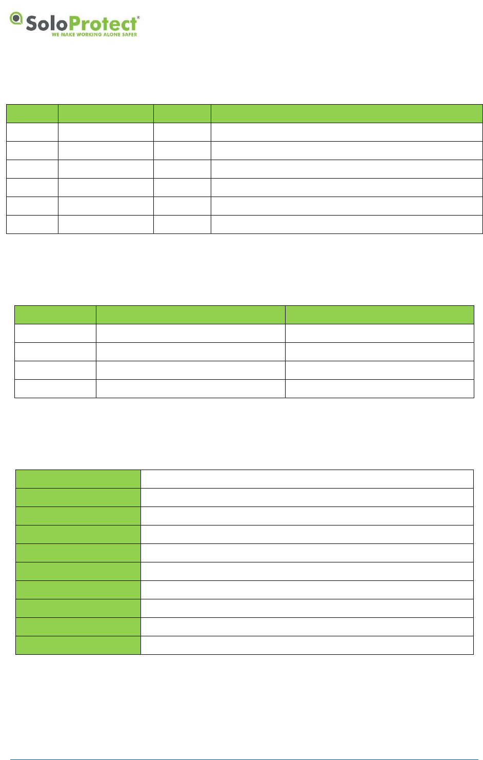
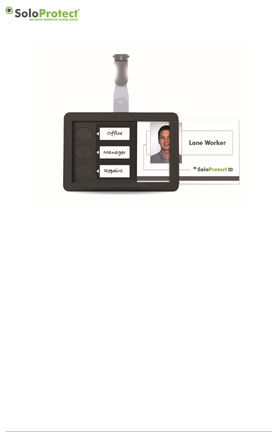
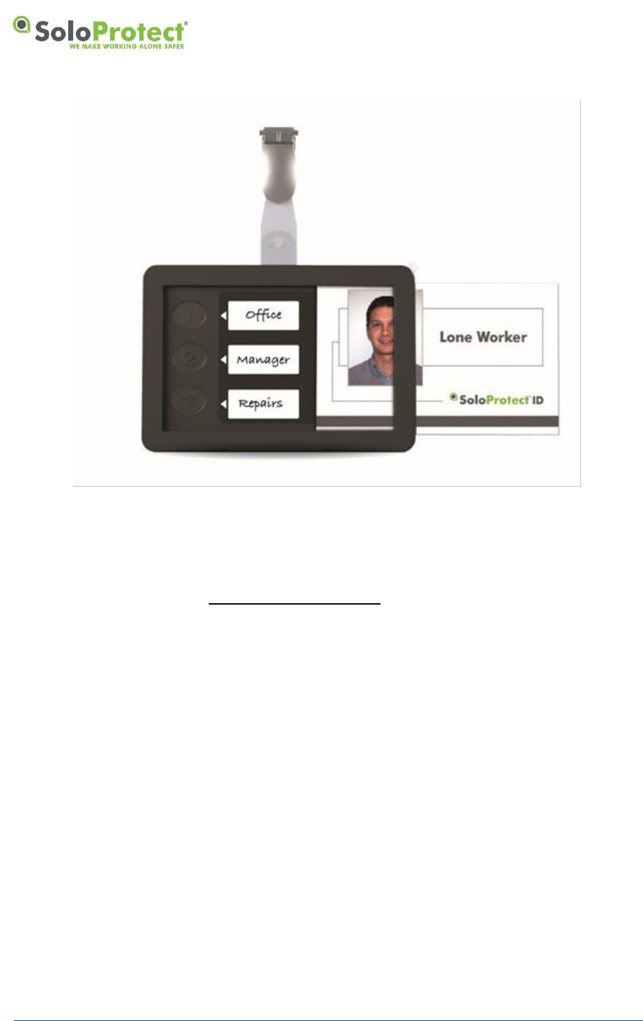
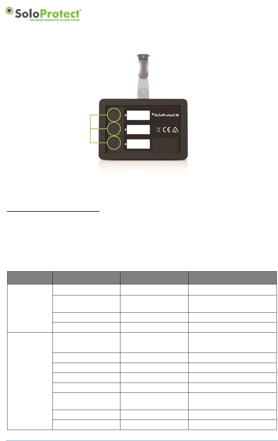
2. SoloProtect ID Layout and Key Functions
2.1 SoloProtect ID Layout
Figure 1: SoloProtect ID Main Functions
2.2 Key Functions
2.2.1 Device Check
This function allows you to check the Battery, Signal and GNSS on your SoloProtect ID and can be
done at any time throughout your working day.
2.2.2 Amber Alert (Status Check in the USA and Canada)*
This function allows you to leave a brief Voice message before you begin each visit or each time you
move location by detailing where you are and for how long.

DISTRIBUTION: INTERNAL + SOLOPROTECT CUSTOMERS
SoloProtect ID US: User Guide
US SoloProtect ID User Guide v2.0 d1909189
© SoloProtect Ltd, 2018 Page 7 of 31
2.2.3 Red Alert
This function allows you to discreetly raise an Alarm to our dedicated Alarm Receiving Centre
whenever you feel vulnerable or threatened.
2.2.4 Incapacitation (ManDown)
This function can automatically initiate a Red Alert if your SoloProtect ID detects you have become
incapacitated.
2.2.5 GNSS (Global Navigation Satellite System)
This function can assist our Alarm Receiving Centre in the event of a Red Alert and is used in
conjunction with your Amber Alert* Voice message to assist in determining your Location.
This function can also be used to log to a secondary Mobile Workforce Platform (MWM).
*Amber Alert is known as a ‘Status Check’ in the USA and Canada
DISTRIBUTION: INTERNAL + SOLOPROTECT CUSTOMERS
SoloProtect ID US: User Guide
US SoloProtect ID User Guide v2.0 d1909189
© SoloProtect Ltd, 2018 Page 8 of 31
3. Initial Set Up and Care and Maintenance
3.1 Initial Set Up
3.1.1 What’s included
The box containing your SoloProtect ID includes the following items:
• SoloProtect ID
• Quick Reference Guide
• Lanyard with Lanyard rip plug pin attached
• Lapel clip
• Charger (including your country’s adapter)
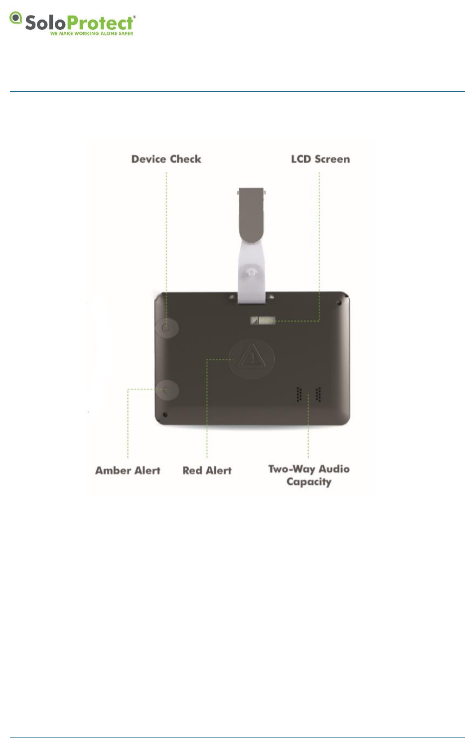
3.1.2 Installing the Lanyard or Lapel Clip
You install the lanyard pin in the corner circled attaching the pin to the longer part of the lanyard. The
shorter part of the lanyard loops into the opposite corner for landscape ID card, or loops into the
corner below for a portrait ID card. The attachment in the circled corner is by way of a plastic pin which
fits tightly in its socket but will pull out if tugged firmly.
Figure 2: Inserting the Lanyard
The pin provided fits in the socket one way only. The pin is held in place by a magnet and pip and the
pin will ‘click’ into its correct location in the socket.
DISTRIBUTION: INTERNAL + SOLOPROTECT CUSTOMERS
SoloProtect ID US: User Guide
US SoloProtect ID User Guide v2.0 d1909189
© SoloProtect Ltd, 2018 Page 9 of 31
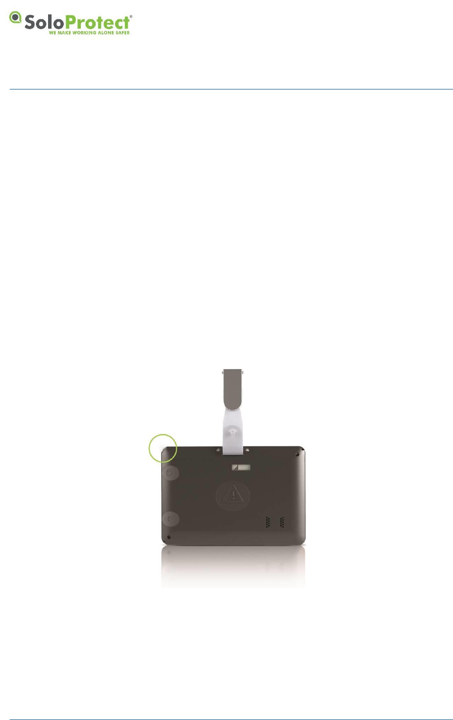
Figure 3: Lanyard PIN
If you do not want to use the lanyard, you can attach a lapel clip as per Figure 2. If you are not using
the lanyard, you must still insert the pin into the socket in the corner circled to prevent dust or dirt from
entering the socket and to ensure the Rip Alert is not activated.
The lanyard is made of one long piece and one short piece joined by a clip. The lanyard pin must be
attached to the long piece. Thread the fine loop at one end of the lanyard part way through the
attachment hole in the pin.
Thread the other end of the lanyard through the loop of cord that has passed through the hole in the
pin. Pull the lanyard tight so that the loop of cord is snug around the pin.
Insert the lanyard pin into its socket highlighted in Figure 2 and Figure 3.
3.1.3 Initial Charge of your SoloProtect ID
Your SoloProtect ID must be fully charged before you attempt to use it to condition the battery fully.
We recommend leaving the device on charge for a minimum of 2 hours the first time it is charged
using the SoloProtect supplied charger.
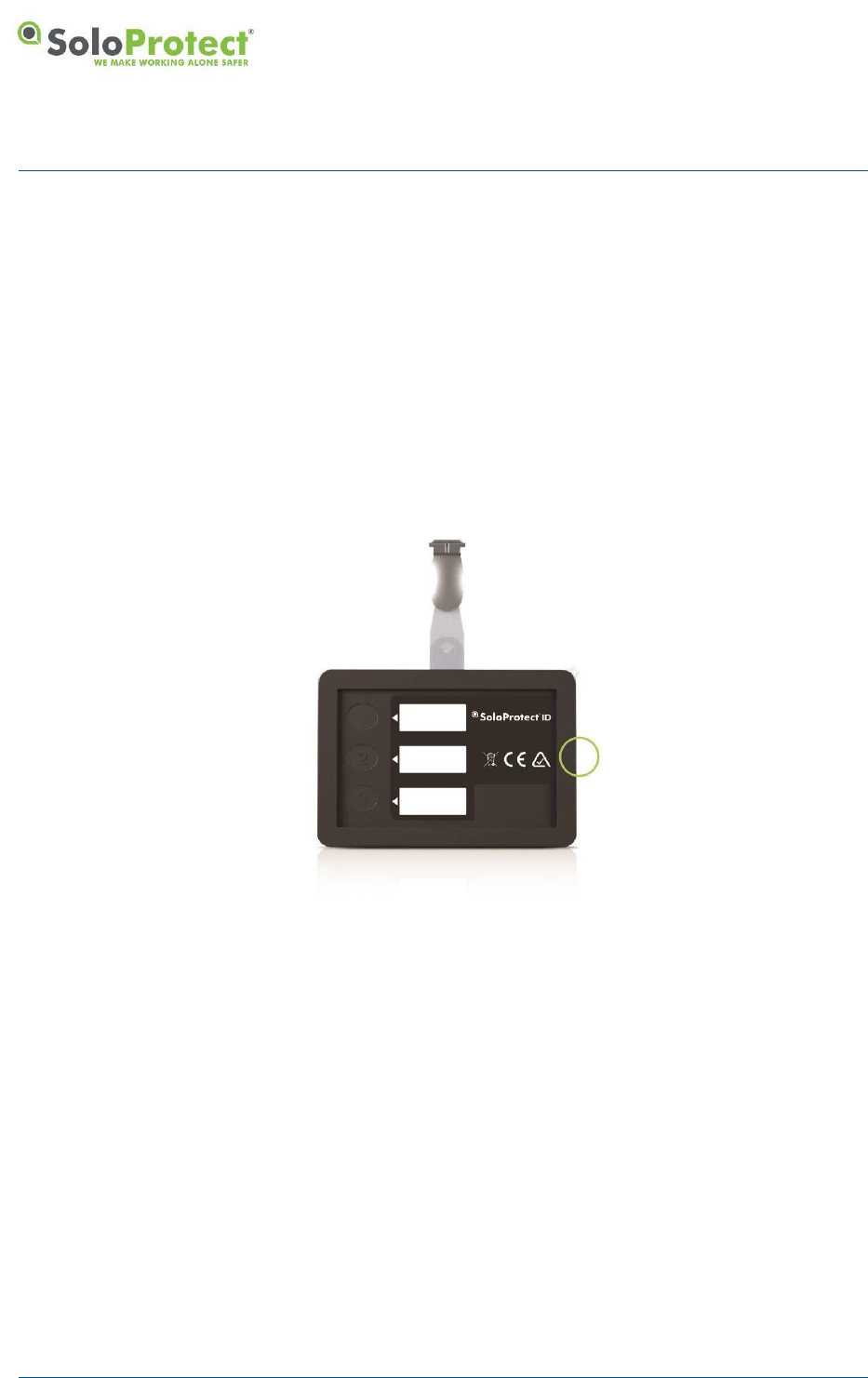
3.1.4 Inserting your ID Card
Fit your ID card into the slot at the right side of your SoloProtect ID (as you look at the front) and slide
it in until it is fully inserted. To remove your card, slide the ID card towards the exit slot. You may
initially feel a slight resistance until the card starts to slide out.
The front of your SoloProtect ID is shown below. With the ID card slid out, you can see the
multifunction user buttons.
DISTRIBUTION: INTERNAL + SOLOPROTECT CUSTOMERS
SoloProtect ID US: User Guide
US SoloProtect ID User Guide v2.0 d1909189
© SoloProtect Ltd, 2018 Page 10 of 31
Figure 4: Inserting an ID card
3.2 Care and Maintenance
SoloProtect ID is purposely designed so that you do not need to perform any routine maintenance
procedures. However, you should note the following points about cleaning and general care.
3.2.1 Cleaning
Use a damp cloth (not wet) to remove any dirt from your SoloProtect ID. Be very careful not to allow
water into the unit.
Do not use any alcohol or chemical cleaning agents of any type.
3.2.2 Moisture Resistance
SoloProtect ID is not waterproof and you should take care not to expose the unit to liquids of any kind,
including water, rain, steam and extreme humidity.
3.2.3 Impact Damage
SoloProtect ID is made from a tough ABS plastic case. It is designed to resist a certain amount of
damage caused by general use, but will not withstand heavy impacts.
DISTRIBUTION: INTERNAL + SOLOPROTECT CUSTOMERS
SoloProtect ID US: User Guide
US SoloProtect ID User Guide v2.0 d1909189
© SoloProtect Ltd, 2018 Page 11 of 31
4. How to Use your SoloProtect ID
4.1 Functionality
4.1.1 Charging
Your SoloProtect ID must be fully charged before you use it. We recommend leaving the device on
charge for a minimum of 2 hours per day or at the end of each shift using the SoloProtect supplied
charger. Your SoloProtect ID cannot be used whilst on charge, however once removed from charge it
is automatically turned on and ready to use.
When your SoloProtect ID is connected to the charger, the battery symbol on the display is active. As
the battery charges, the battery symbol shows more cells and the LEDs change colour from flashing
red, to flashing amber. When the battery is fully charged, the LEDs change to constant green.
Figure 5: Charging your SoloProtect ID
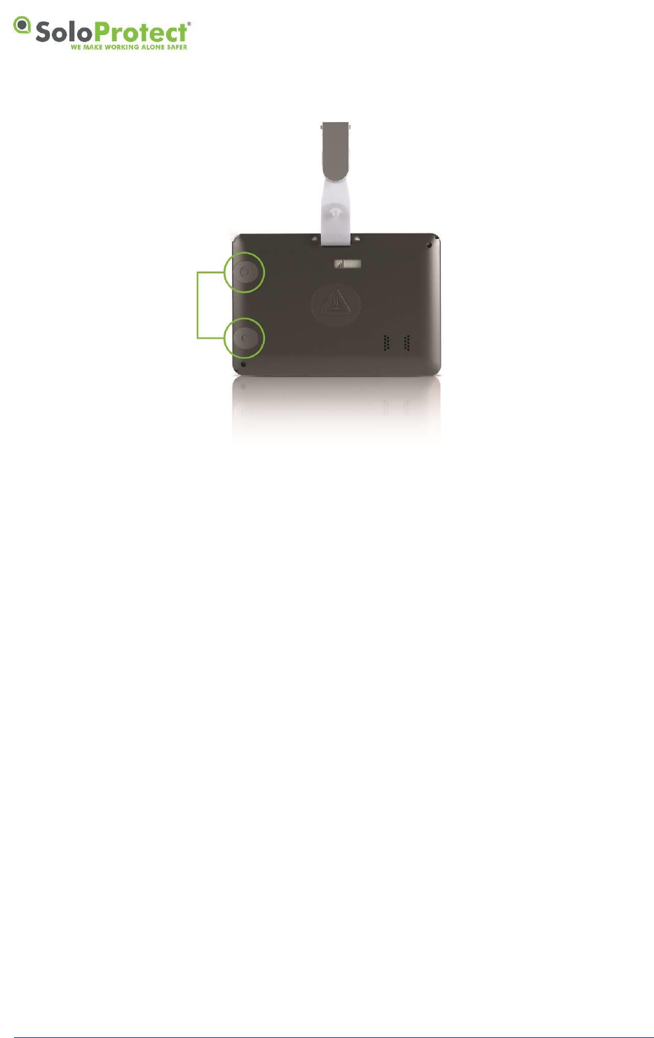
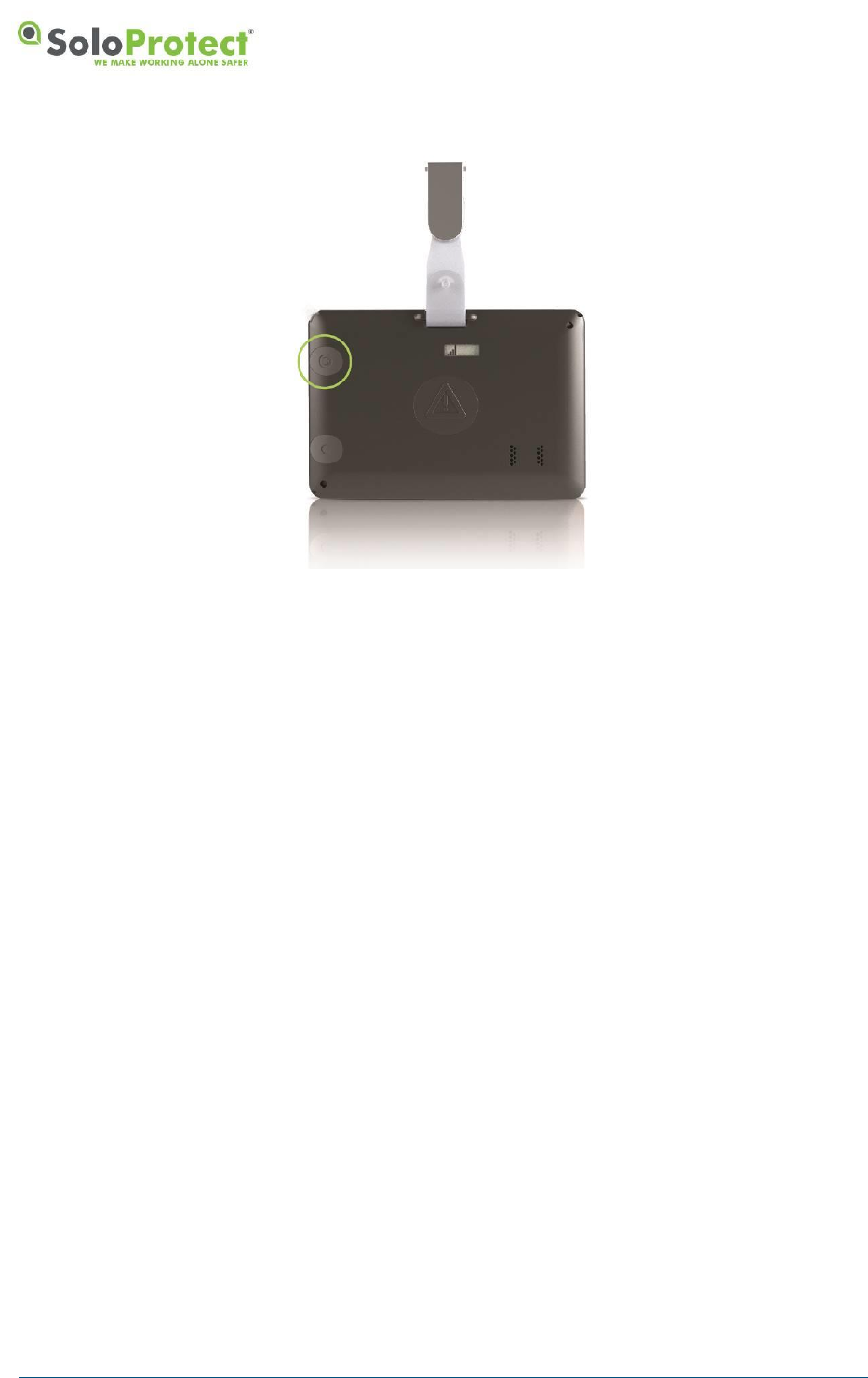
4.1.2 Switching your SoloProtect ID on and off
To check your SoloProtect ID is on, look for the power symbol in the left of the display. You can also
press the Device Check button for 2 seconds. If the LCD and LEDs do not start flashing, the device is
off.
To switch your SoloProtect ID on, press the Device Check and Amber Alert buttons together for 2.5
seconds until the LCD and LEDs start flashing. The device vibrates once briefly to confirm it has
turned on, and then will go through its bootup sequence which also includes 5 further buzzes as well
as displaying all the LED colours and all the LCD symbols. You will also hear beeps out of the
speaker.
To switch your SoloProtect ID off, press the Device Check and Amber buttons together for 2.5
seconds until the device vibrates twice.
DISTRIBUTION: INTERNAL + SOLOPROTECT CUSTOMERS
SoloProtect ID US: User Guide
US SoloProtect ID User Guide v2.0 d1909189
© SoloProtect Ltd, 2018 Page 12 of 31
Figure 6: Turning your SoloProtect ID On and Off
When your SoloProtect ID is on, it registers with the GSM network and is ready to communicate to our
Alarm Receiving Centre.
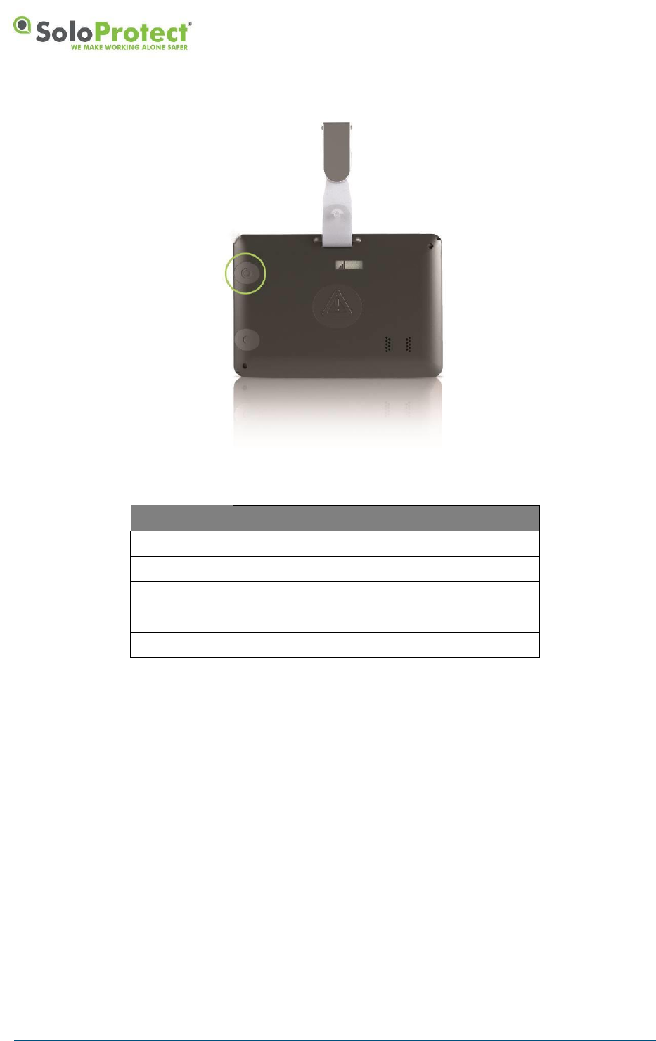
4.1.3 Device Check
You can check your SoloProtect ID battery level and signal strength before each visit or location
change, thus making sure that your SoloProtect ID can operate effectively if needed.
Press and hold the Device Check button for 1.5 seconds until the display and LEDs start to flash. After
a short while, the display will show first the battery symbol and a colour, then the signal symbol and a
colour.
DISTRIBUTION: INTERNAL + SOLOPROTECT CUSTOMERS
SoloProtect ID US: User Guide
US SoloProtect ID User Guide v2.0 d1909189
© SoloProtect Ltd, 2018 Page 13 of 31
Figure 7: SoloProtect ID Device Check
Battery
Symbol
Colour
State
Good
3 cells
Green
>75%
Normal
2 cells
Amber
>35%
Low
1 cell
Amber
<35%
Poor
1 cell (Flash)
Red
<1 hour
Critical
0 cells (Flash)
Red (Flash)
<15 mins
Table 1: Battery Indication Table
DISTRIBUTION: INTERNAL + SOLOPROTECT CUSTOMERS
SoloProtect ID US: User Guide
US SoloProtect ID User Guide v2.0 d1909189
© SoloProtect Ltd, 2018 Page 14 of 31
Signal
Symbol
Colour
Strong
4 bars
Green
Good
3 bars
Amber
Medium
2 bars
Amber
Low
1 bar
Red
Critical
0 bars
Red
Table 2: Signal Indication Table
When both the battery/signal symbols and LEDs have displayed their respective status for five
seconds, the symbols and LEDs are turned off and the device is ready for use.
If either of the LED colours are red, you should not rely on your device in an emergency.
When the battery symbol has only one cell remaining (and has an amber LED colour), you should
recharge your device as soon as possible.
If your SoloProtect ID is consistently indicating Low to Critical Signal, please contact our SoloProtect
Customer Support Team.
If your SoloProtect ID is in an Amber Alert* state or a Red Alert state when the Device check button is
pressed, the LEDs change to amber or red for two seconds to give an indication of the state:
• Constant amber for two seconds indicates an Amber Alert is in progress.
• Constant red for two seconds indicates a Red Alert is in progress – the Alert symbol will be on
the display throughout the alert.
Please note for GNSS enabled devices you will see a blue Satellite Icon at the end of the Device
Check – please refer to the GNSS Section of this manual for further details.
*Amber Alert is known as a ‘Status Check’ in the USA and Canada
DISTRIBUTION: INTERNAL + SOLOPROTECT CUSTOMERS
SoloProtect ID US: User Guide
US SoloProtect ID User Guide v2.0 d1909189
© SoloProtect Ltd, 2018 Page 15 of 31
4.1.4 Amber Alert (Status Check in the USA and Canada)
An Amber Alert is a short voice message to our ARC which is then saved and listened to in the event
of a Red Alert. The more relevant information you leave in this message the more it will help the ARC
Operator in the event of a subsequent Red Alert.
Press the Amber Alert button for at least 1.5 seconds to start an Amber Alert. Your SoloProtect ID
gives three short vibrations to confirm your action.
Figure 8: SoloProtect ID Amber Alert (Status Check in the USA and Canada)
The LEDs show constant amber while the call is being connected and then turns to flashing amber
when the call connection has been made. The flashing amber LEDs are the prompt to start your voice
message. The device will vibrate once when the LEDs switch from constant to flashing to aid
indication that the call is now connected.
Ten seconds before the end of this call period, the LEDs change back to constant amber to warn you
that the call period is soon ending. When the voice call period ends, the LEDs go out.
**When you start the Amber Alert, the device attempts to dial, to allow your voice message to be left. If
the voice call cannot be connected, it will retry connecting the call a number of times. If your call fails
to connect after the retries then your SoloProtect ID will let you know by giving one long vibration.
**If you experience this behaviour consistently, please contact our SoloProtect Customer Support
Team.
*** SAR has been evaluated with a maximum SAR value reported of 0.59W/Kg @ 10mm separation
from head.

DISTRIBUTION: INTERNAL + SOLOPROTECT CUSTOMERS
SoloProtect ID US: User Guide
US SoloProtect ID User Guide v2.0 d1909189
© SoloProtect Ltd, 2018 Page 16 of 31
4.1.5 Amber Alert Timer (Status Check in the USA and Canada)*
An Amber Alert Timer runs for a period of time after your short Amber Voice message has ended.
Your options when in an Amber Alert Timer period are to cancel it, to extend the period, or to allow it
to escalate into a Red Alert.
• You can press the Amber Alert button for more than 1.5 seconds to cancel the Amber Alert
Timer period. This signifies that the potential danger did not arise, or that you are now away
from the hazardous situation. Your SoloProtect ID signals confirmation by giving two short
vibrations.
• You can quickly press the Amber Alert button twice for less than 1.5 seconds per press to
extend the Amber Alert Timer period. The device gives a short burst of vibration to confirm the
extension. The end of the extension period is signalled in the same way as the original Amber
Alert Timer period and you can continue to extend for as long as you need.
• If you do nothing when the Amber Alert Timer period ends, with the implication that you were
not able to take any action, your SoloProtect ID enters the Red Alert state.
You do not have to wait for the signalled end of the Amber Alert Timer period to cancel it or extend it.
Pressing the Amber Alert button for more or less than 1.5 seconds at any time during the Amber Alert
Timer period will cancel or extend the period, as described above.
At the end of the Amber Alert Timer period, the device gives five long bursts of vibration to remind you
to take action.
*Check with your Employer or your SoloProtect Account Manger as to whether you have this function enabled.
4.1.6 Red Alert Activation methods
A Red Alert is a Voice call that can be raised by you if you feel in distress, danger or if injured or
seriously ill. Our dedicated ARC Operators listen, monitor and escalate to Emergency Services if
required.
DISTRIBUTION: INTERNAL + SOLOPROTECT CUSTOMERS
SoloProtect ID US: User Guide
US SoloProtect ID User Guide v2.0 d1909189
© SoloProtect Ltd, 2018 Page 17 of 31
There are 4 ways to activate your Red Alert:
1. Red Alert Button Press - Press and hold the Red Alert Button on your SoloProtect ID
Figure 9: SoloProtect ID Red Alert Button Press
2. Rip Alarm - Forcible removal of the Lanyard Rip pin from your SoloProtect ID eg. Someone
tries to take your SoloProtect ID from you (function not available from the lapel clip).
Figure 10: SoloProtect ID Red Alert from Rip pin
3. Allowing your Amber Alert Timer* to expire - explained in Section 4.1.5
4. Incapacitation Alert (ManDown) - explained in Section 4.1.7

DISTRIBUTION: INTERNAL + SOLOPROTECT CUSTOMERS
SoloProtect ID US: User Guide
US SoloProtect ID User Guide v2.0 d1909189
© SoloProtect Ltd, 2018 Page 18 of 31
When any Red Alert is started, your SoloProtect ID gives three short bursts of vibration to confirm the
state. Your SoloProtect ID opens a voice call to our Alarm Receiving Centre and enables the
microphone, so that our ARC Operators can listen to and/or record the situation.
During an active Red Alert call, your SoloProtect ID will periodically vibrate like a heartbeat (two short
pulses, repeated for the duration of the call) This is to provide reassurance to you that the call is active
and open, and that someone is listening to and/or recording events.
If a Red Alert call is closed accidentally then your SoloProtect ID allows our ARC Operators to dial
back into your device discreetly, you will feel 5 short buzzes. This gives reassurance that the Red Alert
situation is again being monitored.
Additionally, our ARC Operators will be able to talk to you via the loudspeaker in your device. They
will only communicate with you if you make a verbal request to them instructing them to talk. At all
other times our Arc Operators will not speak to maintain the discreet and covert nature of your
SoloProtect ID.
**When you start the Red Alert, the device attempts to dial. If the voice call cannot be connected, it will
retry connecting the call a configured number of times. If your call fails to connect after the configured
amount of retries then your SoloProtect ID will let you know giving 1 long vibration.
**If you experience this behaviour consistently, please contact our SoloProtect Customer Support
Team.
*Amber Alert is known as a ‘Status Check’ in the USA and Canada
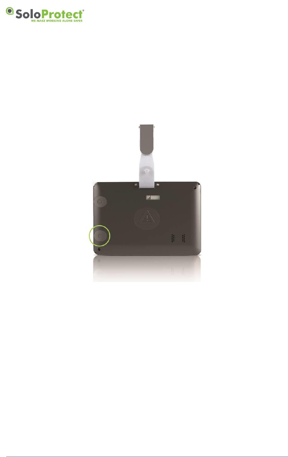
4.1.7 Incapacitation Alert (ManDown)*
SoloProtect ID detects tilt, and non-movement in combination. Typically if tilted and motionless for a
period of 2 minutes (standard set-up), the unit will enter a pre-alarm phase and start to vibrate in order
to make the user aware the device is going to alarm if left unchecked. If the device is not moved for a
further 2 minutes, then it will automatically raise an Incapacitation Alarm and contact our ARC.
When your Incapacitation Alert is started, your SoloProtect ID gives three short bursts of vibration to
confirm the state. Your SoloProtect ID opens a voice call to the designated number and enables the
microphone, so that our ARC Operators can listen to and/or record the situation.
During an active Incapacitation call, your SoloProtect ID will periodically vibrate like a heartbeat (three
short pulses, repeated for the duration of the call) This is to provide reassurance to you that the call is
active and open, and that someone is listening to and/or recording events.
If an Incapacitation call is closed accidentally then your device allows our ARC Operators to dial back
into your device discretely, you will feel 5 short buzzes. This gives reassurance that the Red Alert
situation is again being monitored.
Additionally, our ARC Operators will be able to talk to you via the loudspeaker in your device.

DISTRIBUTION: INTERNAL + SOLOPROTECT CUSTOMERS
SoloProtect ID US: User Guide
US SoloProtect ID User Guide v2.0 d1909189
© SoloProtect Ltd, 2018 Page 19 of 31
Figure 11: SoloProtect ID Loud Speaker during Incapacitation Alarm
Incapacitation detection is always disabled when the unit is on its charger or switched off.
*Check with your Employer or your SoloProtect Account Manger as to whether you have this function enabled.
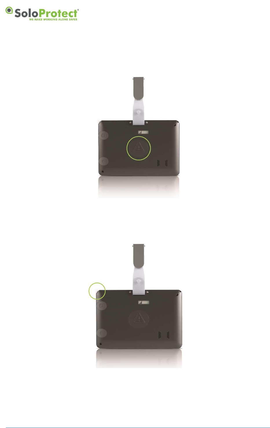
4.1.8 Closing down your Red Alert or Incapacitation Alert (ManDown)
Once you feel that your situation no longer needs monitoring you can close your Alert down.
If your Red Alert activation was raised by the Rip Alarm, you must first re-insert the lanyard plug.
The Red Alert call can only be closed by you. After you feel your set of 2 vibrations or 3 vibrations,
press and hold the Red Alert button for 1.5 seconds, you will feel 2 longer vibrations. You Red Alert
call is now closed.

DISTRIBUTION: INTERNAL + SOLOPROTECT CUSTOMERS
SoloProtect ID US: User Guide
US SoloProtect ID User Guide v2.0 d1909189
© SoloProtect Ltd, 2018 Page 20 of 31
Figure 12: Closing a Red Alert Alarm
4.1.9 GNSS (Global Navigation Satellite System)
Your SoloProtect ID can be configured so that a GNSS Location request is made in the following
situations:
• When you press any of your SoloProtect ID buttons
• When you check the status of your SoloProtect ID
• When you enter an Amber Alert state*
*Amber Alert is known as a ‘Status Check’ in the USA and Canada
• When you enter a Red Alert state
• To log into a SoloProtect Mobile Management Platform (MWM)*
*MWM - please contact your Business Development Manager for more details of this service
In the event of a serious incident, transmission of your location along with your Amber Alert Voice
message will help ensure a speedier response in sending you assistance.
Your current GNSS location fix status is transmitted at the end of a Device Check. The Satellite LCD
and LED flashes blue for up to two minutes if the device is searching for a GNSS fix and displays a
steady blue for five seconds if the latest GNSS location fix gave a valid location. The steady blue “valid
GNSS fix” indication is accompanied by a single short vibration.
DISTRIBUTION: INTERNAL + SOLOPROTECT CUSTOMERS
SoloProtect ID US: User Guide
US SoloProtect ID User Guide v2.0 d1909189
© SoloProtect Ltd, 2018 Page 21 of 31
Figure 13: GNSS fix – Device Check
Your GNSS location is also requested and transmitted during any open Red Alert Voice call.
You should always perform a Device Check and get a GNSS location fix after turning your SoloProtect
ID on or moving outside from indoors.
GNSS requires a clear line of sight to the sky, not obstructed by buildings or other obstacles. The
GNSS location operation will not work whilst the unit is indoors.
4.1.10 Multifunction Buttons – UK*
The 3 multi-function buttons on the front of the device are usually covered by your ID Card. These
buttons are not designed for discreet use or to be deployed as part of a situation where you require
assistance due to your safety being compromised.
Your SoloProtect ID can be configured so that 3 buttons underneath the ID card can be used to:
• Make a non-emergency phone call to a pre-defined phone number when you press a button
• Send a non-emergency SMS to a pre-defined phone number when you press a button
• To log to a SoloProtect Mobile Management Platform (MWM)*
*MWM - please contact your Business Development Manager for more details of this service
For example, these buttons can be programmed to let a Manager or authorised person know you have
returned safely home after a shift or you have arrived safely at a visit.
DISTRIBUTION: INTERNAL + SOLOPROTECT CUSTOMERS
SoloProtect ID US: User Guide
US SoloProtect ID User Guide v2.0 d1909189
© SoloProtect Ltd, 2018 Page 22 of 31
Figure 14: Multifunction or User Buttons
*Check with your Employer or your SoloProtect Account Manger as to whether you have this function enabled.
4.2 Ready2Talk (US and Canada only) – Multi-Function Buttons*
The 3 multi-function buttons on the front of the device are usually covered by your ID Card. These
buttons are not designed for discreet use or to be deployed as part of a situation where you require
assistance due to your safety being compromised.
A Pre-designated multi-function button can be used to trigger a live 2-way voice call to the SoloProtect
EDC via the Ready2Talk function. SoloProtect Ready2Talk is only to be used in non-alarm situations.
For example, if you have an uneasy feeling when walking to your vehicle late at night, it would be
appropriate to initiate Ready2Talk so that you have the added comfort of talking to an Operator until
you reach your vehicle.
DISTRIBUTION: INTERNAL + SOLOPROTECT CUSTOMERS
SoloProtect ID US: User Guide
US SoloProtect ID User Guide v2.0 d1909189
© SoloProtect Ltd, 2018 Page 23 of 31
Figure 15: Ready2Talk (US and Canada only) – Multi-Function Buttons
*Check with your Employer or your SoloProtect Account Manger as to whether you have this function enabled.
Only available in the US and Canada.
4.3 SoloProtect ID Key Indicators
4.3.1 LCD and LED Table
The following table summarises the indications given by your SoloProtect ID, both by the LCD/LEDs.
Device state
Symbol
LED
Meaning
On charge
1 battery cell (flash)
Red (flash)
Trickle charging
2 or 3 battery cells (1 cell
flashing)
Amber (flash)
Charging
3 battery cells
Green
Charging complete
Battery Outer Only
Purple
Charging Fault Occurred
Device checking
Battery (flash)
Signal (flash)
Red (flash)
Indicates start of status display
3 battery cells
Green
Battery condition good (>75%)
2 battery cells
Amber
Battery condition normal (<75%)
1 battery cell
Amber
Battery condition low (<35%)
1 battery cell (Flash)
Red
Battery condition poor (<1 hour)
0 battery cells (Flash)
Red (Flash)
Battery condition critical (<15
mins)
4 signal bars
Green
Signal quality strong
3 signal bars
Amber
Signal quality good
DISTRIBUTION: INTERNAL + SOLOPROTECT CUSTOMERS
SoloProtect ID US: User Guide
US SoloProtect ID User Guide v2.0 d1909189
© SoloProtect Ltd, 2018 Page 24 of 31
Device state
Symbol
LED
Meaning
2 signal bars
Amber
Signal quality medium
1 signal bar
Red
Signal quality low
0 signal bars
Red
Signal quality – none or critical
Alert
Amber (2 secs)
An Amber Alert is in progress
(Device Check in the USA and
Canada)
Alert
Red (2 secs)
A Red Alert is in progress
GNSS
Blue (flash)
Searching for a valid GNSS
location fix
GNSS
Blue (5 secs)
A valid GNSS location fix was
found
Amber Alert
(Device Check
In the USA and
Canada)
Alert
Amber
Call being connected, and then
also for last 10 seconds of call
Alert
Amber (flash)
Call connected (until last 10
seconds)
Red Alert
Alert
None
Red alert active
Incapacitation
(Mandown)
Alert
Red
Pre Alert and subsequent
Incapacitation alarm active
Multi-Function
Call
(Ready2Talk)
None
Blue
Call being connected, and then
also for last 10 seconds of call
None
Blue (flash)
Call connected (until last 10
seconds)
At power on
All symbols, then
battery/signal (flash)
Cycle through colours,
then Red (flash)
Critical Battery or Signal
battery/signal (alternate
flash)
Red (alternate flash),
then device power off
Signal Fault or Issue
Table 3: LED/LCD Indication Table
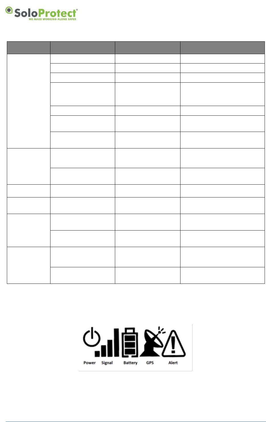
Figure 16: LCD Symbols
DISTRIBUTION: INTERNAL + SOLOPROTECT CUSTOMERS
SoloProtect ID US: User Guide
US SoloProtect ID User Guide v2.0 d1909189
© SoloProtect Ltd, 2018 Page 25 of 31
4.3.2 Vibration Patterns
The following table summarises the vibration indications given by your SoloProtect ID. The Vibration
patterns aid the use of SoloProtect ID for the visually impaired.
SoloProtect ID Action
Vibration pattern
Confirmation of switch to Power On mode
Single short pulses
Confirmation of switch to Power Off mode
Two short pulses
Confirmation of start of Device Check
Three short pulses
Confirmation that neither the network
coverage or battery strength are red
Single short pulse
Confirmation that the latest GNSS location
fix gave a valid location
Single short pulse
Confirmation of start of Amber* or Red Alert
Three short pulses
‘Heartbeat’ confirmation of Red Alert call
still active
Two short pulses (at
configured interval)
Confirmation to commence voice message
on Amber Alert*
Single short pulse
End of Amber Alert Timer* period – action
required or a Red Alert will follow
Five long pulses
Confirmation of extension of Amber Alert*
period
Single short pulse
Confirmation of termination of Amber Alert*
Two short pulses
Confirmation of termination of Red Alert
Two longer pulses
Confirmation of start of Multi-Function call
(ready2talk)
Two short pulses
Confirmation of start of Multi-Function SMS
Three short pulses
Incapacitation (ManDown) Pre-Alert warning
Continual long pulses
and beeps for the
duration of the Pre-
Alert period
Confirmation of start of Incapacitation
Five short pulses
‘Heartbeat’ confirmation of Incapacitation
Red Alert call still active
Three short pulses (at
configured interval)
ANY call requested but out of coverage –
unable to make Voice call
Single long pulse
*Amber Alert is known as a ‘Status Check’ in the USA and Canada
Table 4: Vibration indication Table
DISTRIBUTION: INTERNAL + SOLOPROTECT CUSTOMERS
SoloProtect ID US: User Guide
US SoloProtect ID User Guide v2.0 d1909189
© SoloProtect Ltd, 2018 Page 26 of 31
5. SoloProtect ID Technical Specification
5.1 Technical Specification Table
Data
Item
Dimensions
95 x 65 x 12 mm
Overall weight
70g (not including lanyard)
Operating temperature range
-10C to +40C
Operating humidity range
0-95% non-condensing
Communication system
Dual-band GSM
GSM frequency – Dual-band
850 MHz, 1900 MHz
Battery life – standby
48 hours (estimated)
Battery life – talk time
3 hours (estimated)
Case
ABS plastic
SAR level (see below)
1.46 W/kg @ 0mm separation from body
SAR level (see below)
0.59 W/kg @ 10mm separation from head
GNSS
SiRF Star V
Acquisition: -146 dBm
Tracking: - 165dBm
FCC ID
Contains FCC ID: VTJS10977U
Industry Canada
Contains IC: 7467A-S10977U
Table 5: Technical Specification Table

DISTRIBUTION: INTERNAL + SOLOPROTECT CUSTOMERS
SoloProtect ID US: User Guide
US SoloProtect ID User Guide v2.0 d1909189
© SoloProtect Ltd, 2018 Page 27 of 31
5.2 Compliance with FCC and IC Rules and Regulations
FCC Compliance Statement and RF Exposure Statement
The SOLO-ID-US device complies with Part 15 of the FCC Rules. Operation is subject to the
following two conditions: (1) This device may not cause harmful interference, and (2) This device must
accept any interference received, including interference that may cause undesired operation.
This equipment complies with FCC RF radiation exposure limits set forth for an uncontrolled
environment. SAR has been evaluated with a maximum SAR value reported of 1.46W/kg @ 0mm
separation from body and 0.59W/Kg @ 10mm separation from head. This transmitter must not be co-
located or operating in conjunction with any other antenna or transmitter.
IC Compliance Statement
This device complies with Industry Canada licence-exempt RSS standard(s). Operation is subject to
the following two conditions: (1) this device may not cause interference, and (2) this device must
accept any interference, including interference that may cause undesired operation of the device.
Le présent appareil est conforme aux CNR d'Industrie Canada applicables aux appareils radio
exempts de licence. L'exploitation est autorisée aux deux conditions suivantes : (1) l'appareil ne doit
pas produire de brouillage, et (2) l'utilisateur de l'appareil doit accepter tout brouillage radioélectrique
subi, même si le brouillage est susceptible d'en compromettre le fonctionnement.
The SOLO-ID-US has been designed to comply with safety requirements for exposure to radio waves
(SAR). SAR testing has been performed in accordance with RSS-102, with the SOLO-ID-US
transmitting at its highest certified power level in all used frequency bands. The highest SAR value for
the SOLO-ID-US when tested was 1.46W/Kg @ 0mm separation from body and 0.59W/Kg @ 10mm
separation from head. Please follow the instructions included in the user guide for product installation
and use.
Le SOLO-ID-US est conçu pour se conformer aux exigences de sécurité pour l'exposition aux ondes
radio (SAR). Tests SAR a été effectué conformément à la norme RSS-102, avec le SOLO-ID-US à
son niveau de puissance maximum certifié dans toutes les bandes de fréquences utilisées. La valeur
SAR maximale pour le SOLO-ID-US lorsqu'il est testé était 1.46W/Kg @ 0mm de séparation du corps
et 0.59W / Kg @ 10mm de séparation de la tête. S'il vous plaît suivez les instructions incluses dans le
guide utilisateur pour l'installation du produit et son utilisation.
Changes or modifications to this unit not expressly approved by the party responsible for compliance
could void the user’s authority to operate the equipment.
5.3 Risks Associated with Pacemakers
Due to the maximum SAR values, SoloProtect ID should not impair the performance of implanted
pacemakers. However, the general recommendation is to maintain at least 15 centimetres between a
GSM-based device and a pacemaker. If you are in any doubt, seek advice and clarification from your
physician and/or the manufacturer of your specific pacemaker.
Numerous studies have been performed to assess the risks of such devices impairing the correct
functioning of pacemakers.
There is a general consensus across the studies found in regard to the following:
• The degree of protection of pacemakers against the effects of RFEE depend on the design of
pacemaker. The latest pacemakers with ceramic filters appear to immune to RFEE.

DISTRIBUTION: INTERNAL + SOLOPROTECT CUSTOMERS
SoloProtect ID US: User Guide
US SoloProtect ID User Guide v2.0 d1909189
© SoloProtect Ltd, 2018 Page 28 of 31
• Exposure to pacemakers of RFEE depends on the proximity of the mobile phone type device.
Recommendations suggest the minimum distance between pacemaker and mobile phone
type device to be in the range 10 – 20 cm.
• Exposure to pacemakers of RFEE depends on the RFEE emission levels of the mobile phone
type device.
• The effects of interference due to exposure to RFEE in pacemakers are temporary. Once the
source of RFEE emissions is removed the pacemaker reverts back to correct functionality.
• Mobile phone based devices can potentially cause interference with pacemakers when in use
on a call and when in standby, but not when turned off.
• Those at highest risk are individuals who are completely dependent on pacemakers (those
individuals that cannot generate spontaneous cardiac rhythm).
Part of the conclusion in the above mentioned testing is that due to its low SAR value ‘There is very
low health risk for persons with cardiac pacemakers or other active medical implants’
Regardless, if in any doubt the wearer should seek advice from their doctor or the manufacturer of
their pacemaker.
5.4 Risks Associated with Pregnancy
Referring to the previous statement above on Specific Absorption Rate (SAR).
Due to the relatively low maximum SAR value, SoloProtect ID should not pose any risk to individuals
whilst pregnant. Any user of SoloProtect ID who registers any concern about using SoloProtect ID
whilst pregnant should seek advice from their GP.’
5.5 Use of SoloProtect ID in Restricted Areas
As with mobile phones, should be in accordance with regulations, protocols and stipulations relating to
the specific environment. Where the use of mobile phones is prohibited, SoloProtect ID should be
turned off. There may be risks associated with interference with equipment sensitive to RFEE (such as
aircraft, hospitals and healthcare facilities) or potentially explosive environments (such as petrol
stations and chemical plants).
5.6 Disposal and Recycling Information
This product must not be disposed of as unsorted municipal waste. Please dispose of this product in
accordance with local environmental laws and guidelines, by returning it to your point of sale or to your
municipal collection point for recycling. Note that this product contains a battery that cannot be
removed by the customer. For advice on disposal, please contact SoloProtect.

DISTRIBUTION: INTERNAL + SOLOPROTECT CUSTOMERS
SoloProtect ID US: User Guide
US SoloProtect ID User Guide v2.0 d1909189
© SoloProtect Ltd, 2018 Page 29 of 31
6. SoloProtect ID Warranty
Please refer to the Terms and Conditions in Section 13 - Warranties of your SoloProtect Client Service
Agreement for more details or Contact your SoloProtect Account Manager.
DISTRIBUTION: INTERNAL + SOLOPROTECT CUSTOMERS
SoloProtect ID US: User Guide
US SoloProtect ID User Guide v2.0 d1909189
© SoloProtect Ltd, 2018 Page 30 of 31
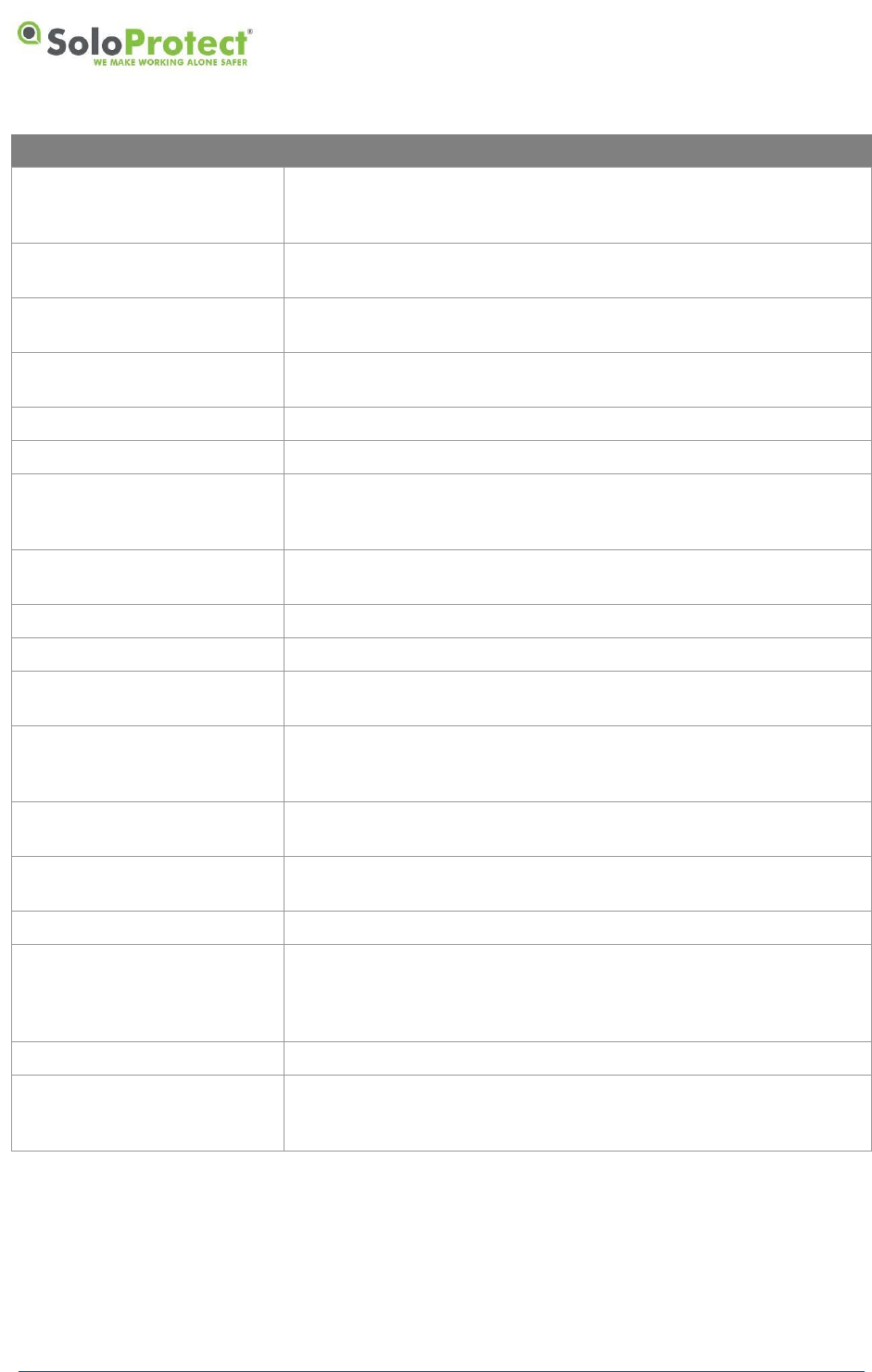
7. Glossary of Terms
Term
Definition
2G
Second Generation wireless telephone technology which digitally
encrypts calls and messages for a specific recipient.
AGC
Automatic Gain Control.
AGNSS, A-GNSS
Assisted GNSS
Alert
an inbound call, message, or event to an ARC.
Amber Alert (device Check in
USA and Canada)
an alert left at the ARC detailing the users current location, situation,
and status in order to aid the operator in dealing with any subsequent
alerts.
APN
Access Point Name
ARC
Alarm Receiving Centre – a 24/7 communications centre that
answers calls from lone worker devices and responds as required.
BS8484
a British Standard on the provision of lone worker services and
devices.
CLI
Caller Line Identification often known as Caller ID
Config Server
This Server processes and transmits configuration data to a
SoloProtect ID device so that it can be reprogrammed remotely.
COTS
Commercial Off The Shelf
EDGE
Enhanced Data rates for GSM Evolution – allows improved data
transmission rates over the GSM network.
Event Log
Record of specific data recorded and time stamped. This includes
GNSS location fix data and Device checks.
Geo-fence
A virtual boundary i.e. one based on location rather than a physical
fence, wall etc. A geo-fence is usually defined as a radius about a
fixed point defined by latitude and longitude coordinates.
GNSS
Global Navigation Satellite System such as GPS, Glonass, and
similar.
GPRS
General Packet Radio Service – a more reliable and faster means of
sending data over the GSM network than SMS messaging.
GPS
See GNSS
GSM
Global System for Mobile Communications – a standard for cellular
mobile communications, as used today for most mobile phones.
Heartbeat
an indication to the user periodically that shows the device is actively
in alert mode and transmitting to the ARC.
ICCID
SIM Serial Number
SoloProtect ID
a cellular based lone worker device based around an Identity Card
Holder.
IMSI
International Mobile Subscriber Identity – a unique number that
identifies a particular SIM and thus a particular subscriber account.
DISTRIBUTION: INTERNAL + SOLOPROTECT CUSTOMERS
SoloProtect ID US: User Guide
US SoloProtect ID User Guide v2.0 d1909189
© SoloProtect Ltd, 2018 Page 31 of 31
Term
Definition
Lone Worker Device
a device defined under standard BS8484 for the protection of
workers who have risk of attack or incapacitation hazards whilst
operating out of line of sight of co-workers.
Incapacitation
an event/status where the user is physically incapacitated – usually
occurring following a slip, trip, or fall.
Incapacitation Alert
a high priority Incapacitation event requiring an immediate respond
from the ARC
Mapping/Logging Server
This receives and stores all mapping/logging data from the device so
it can be accessed by the ARC (Alarm Receiving Centre) if needed.
MNC
Mobile Network Code
Monitoring Station
see ARC
MWM
Mobile Workforce Management – a web based mapping and alerting
platform provided to SoloProtect customers to provide enhanced
features for their user base.
NFC
Near Field Communications – an RF technology that allows two
items to communicate when in close proximity.
OS
Operating System
PPP
Point to Point Protocol
Red Alert
a high priority user triggered event requiring an immediate respond
from the ARC
SIM
Subscriber Identity Module – a secure store for the subscriber
information (e.g. the IMSI) for mobile equipment (e.g. GSM modem
or phone).
SMS
Short Message Service – a text-based message facility for GSM
phones.
SoloProtect
SoloProtect – A lone worker device manufacturer and monitoring
services provider.
SP,SPUK
see SoloProtect
TCP/IP
Transmission Control Protocol/Internet Protocol – the standardized
suite of protocols used to connect hosts over the internet. It provides
end-to-end connectivity specifying how data should be formatted,
addressed, transmitted, routed and received at the destination.
TTFF
Time To First Fix
User Profile
a User Profile is a set of information about the device user stored at
the ARC for the purpose of assisting the operator in handling any
Alert.
Table 6: Glossary of Terms