Somfy Systems CSZ SWF Cellular Shade Radio ZWave CSZ1 User Manual
Somfy Systems SWF Cellular Shade Radio ZWave CSZ1 Users Manual
Users Manual
Owner’s Manual
Virtual Cord™ Motorized Shades
2
Please be sure to read and remove the securing tape and label before operating your motorized shade.
About Your Motorized Shade
Motorized shades offer a convenient solution to everyday challenges. They provide instant privacy,
glare reduction, and eliminate the need to manually adjust shades. Motorized shades also eliminate
dangerous cords and create a comfortable and energy efcient environment. Motorized shades
feature Z-Wave Radio technology, Z-Wave is omnidirectional and operates within a range of 65 feet,
eliminating the need to aim the remote.
Z-Wave is the most widely used radio protocol in leading home automation systems, making
integration simple and inexpensive.
About your Motorized Shade .............................................................................................................. 2
Basic Shade Control ........................................................................................................................... 3
Control Features .................................................................................................................................. 3
Home Button - Single-Channel Remote ............................................................................................. 3
LED (Light Locations and Indications .................................................................................................. 4
Program Buttons ................................................................................................................................. 4
Adusting your Shade’s Default Upper Limit (optional) ........................................................................ 5
Adjusting your Shade’s Default Lower Limit (optional) ........................................................................ 5
Adjusting your Shade’s Home position (optional) ............................................................................... 6
Adjusting a Group of Shades ......................................................................................................... 6 - 7
Reversing Motor Direction ................................................................................................................... 8
Denitions and Descriptions Used for Programming .......................................................................... 9
Joining a Controller to a Motor .......................................................................................................... 10
Assigning the Single-Channel Remote as Primary ............................................................................ 11
Joining Additional Remotes to a Network ......................................................................................... 12
Joining an Existing Z-Wave Network ................................................................................................ 13
Removing a Device from a Hub ........................................................................................................ 13
Network Reset ................................................................................................................................... 14
Factory Limits Reset .......................................................................................................................... 14
Local Reset ........................................................................................................................................ 14
Table of Contents
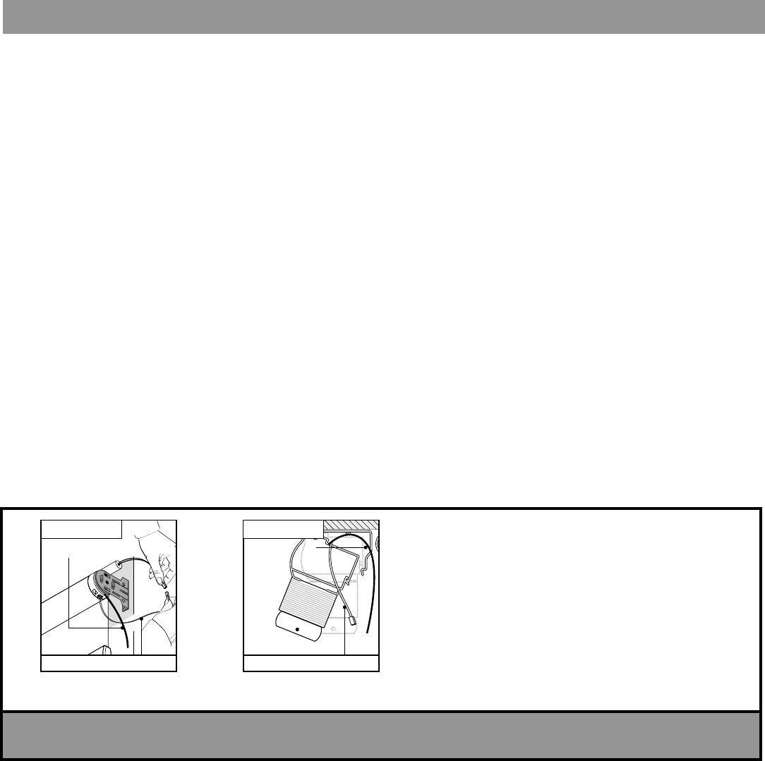
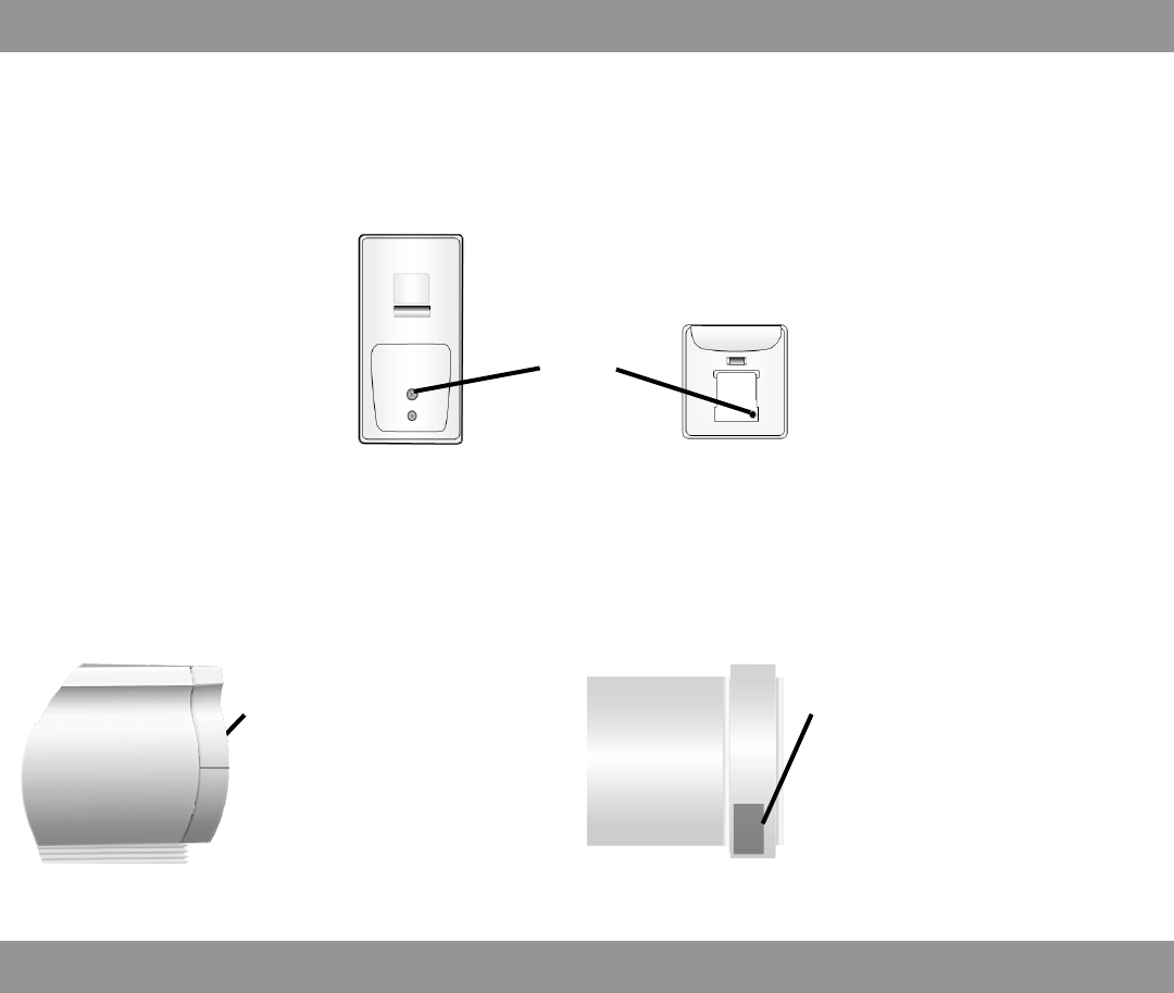
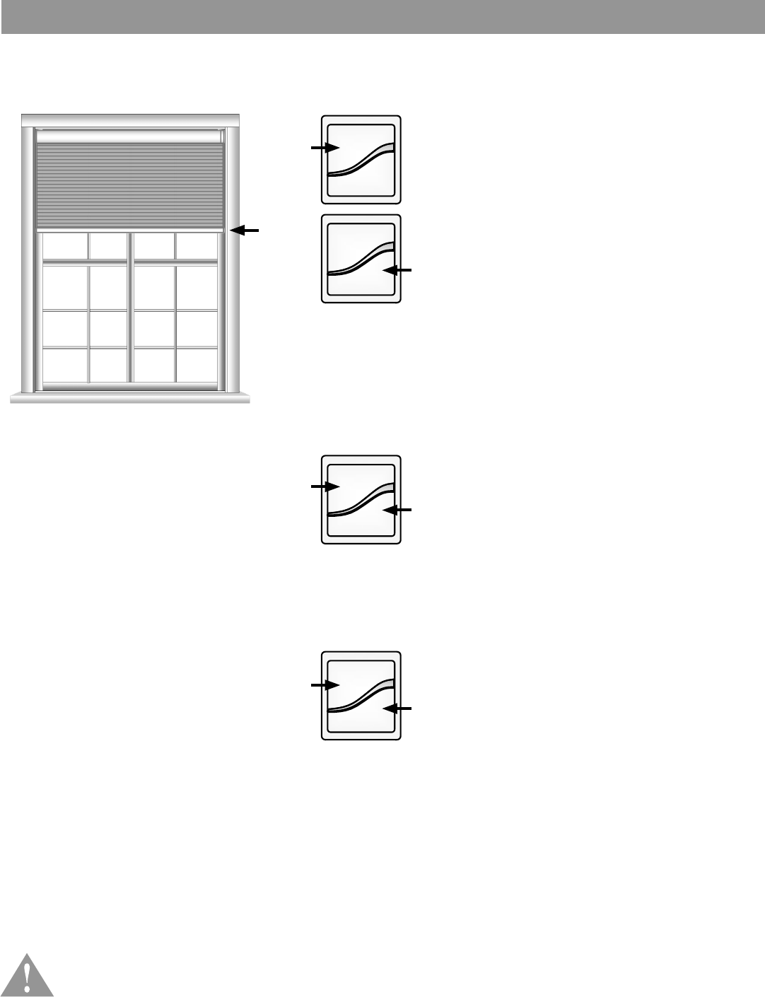
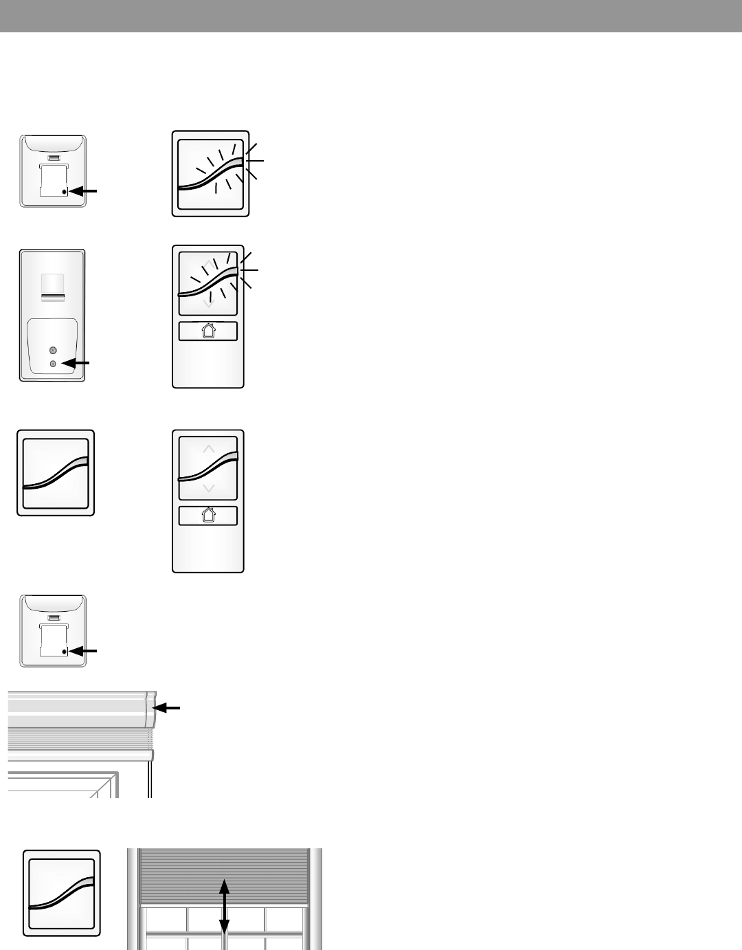
Remove securing tape and position motor
RF antenna wire and power cable away
from roller tube (see A) or outside of headrail
(see B) depending upon product type.
Avoid crimping or damaging the antenna and
power lead during installation process.
NOTE: RF antenna should be visible
(exposed outside headrail) for greatest RF
range. In some cases, RF antenna wire may
need to be repositioned for
optimal performance.
A. Solar, Roller,
Artisian Fabric, Natural
RF Antenna wire
Power cable/
B. Cellular, Pleated,
Classic Roman
Power cable
RF Antenna wire
ATTENTION! IMPORTANT INSTALLATION INFORMATION
¡ATENCIÓN! INFORMACIÓN IMPORTANTE SOBRE LA INSTALACIÓN
GRA BE R
GRA BE R
GRA BE R
GRA BE R
GRA BE R
3
Basic Shade Control
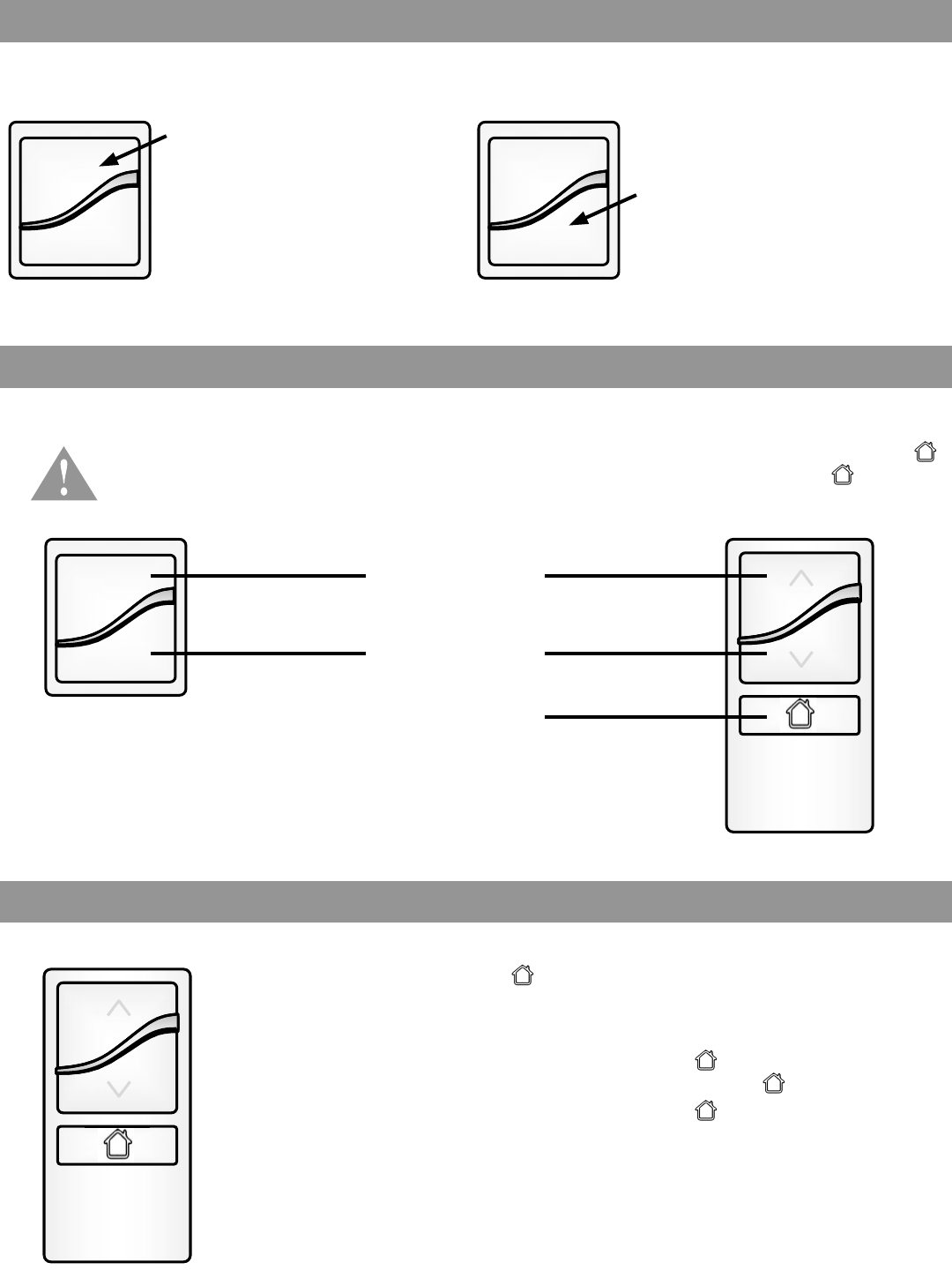
Control Features
Home Button − Single-Channel Remote
Upon rst power up, you will see a green light illuminate on the headrail or motor end of the shade. This will happen
whenever power is rst applied or restored after an outage. Press the UP or DOWN button to operate the shade.
Note: you can press and release the opposite directional button to stop the shade while it is in motion.
Operating your shade with the two-button remote or optional single-channel remote.
button: Acts as a STOP button while shade is in
motion. It can also be programmed as a quick way to
bring shades to your preferred intermediate position.
1. Press and releasing while your shade is at rest
will bring your shade to your position.
2. Press and releasing while the shade is in motion
will stop the shade.
Press and
release the
UP button
to fully open
the motorized
shade.
Press and
release the
DOWN button
to fully close
the motorized
shade.
Your controls have been pre-programmed to control your shade. The upper and lower limits and
position have already been set. If you are not satisfied with the default upper, lower, or position
of your shade, see steps in the following sections of this manual.
UP Button
DOWN Button
HOME Button
(Intermeidate/favorite)
GRA BE R GRA BE R
4
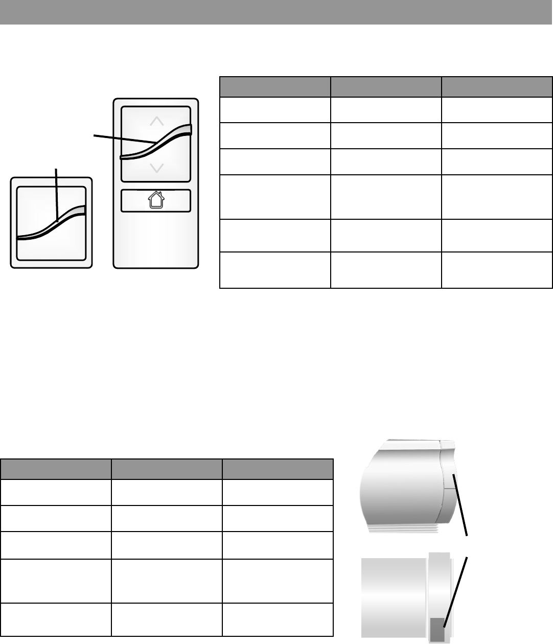
LED (Light) Locations and Indications
LED Light Bar
Light indicator
on the front of
the controls
Shade LED
Light indicator on
the shade end
Remote LED Indications
Operation on LED light bar:
Replacement battery: #CR2430
Shade LED Indications
There is a discreet LED located on the end of your shade to provide
additional valuable feedback. In bright conditions, it may be difcult to
see, so steps may need to be taken for limit light for better visibility.
Replacement batteries: 8AA Lithum per battery case; larger shades may
require multiple battery cases
LED Colors When Definition
Green blinking After operation Battery is good
Amber blinking After operation Battery is low
Red Blinking After operation Battery is dead
Solid green to solid
amber to ashing
green
From user mode Entering a
programming state
Solid amber to
blinking green From user mode Leaving a
programming state
Flashing amber to
blinking green From user mode Intermediate limit set
LED Colors When Definition
Amber blinking After operation Battery is at 20%
Red blinking After operation Battery is dead
Red/green alternating From user mode Entering a
programming state
blinks green then
turns off From user mode Leaving a
programming state
Solid green then
turns off From user mode Setting an
intermediate position
5
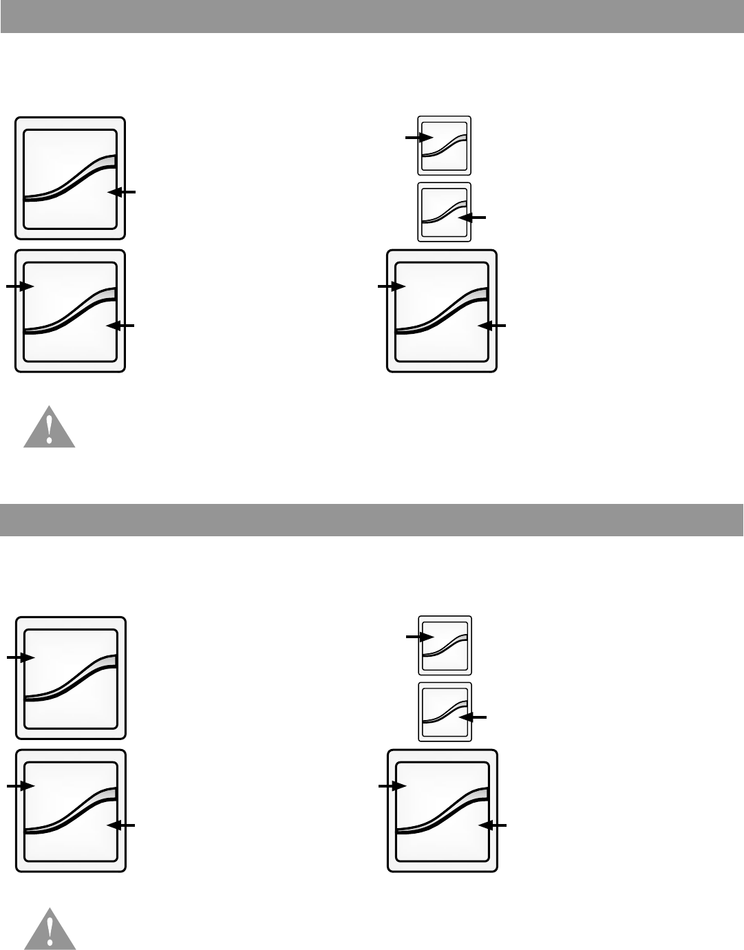
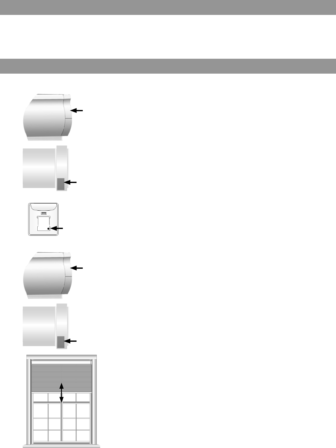
Program Buttons
Installation Notes
Cellular and Pleated
and Roman
Located on the
headrail
Single-Channel Remote
BACK VIEW BACK VIEW
Two-Button Remote
Program
Button
Solar, Roller, Natural, and
Soft Shades
Located on the motor end
Program Button (remote)
Button on the back of the Virtual Cord or single-channel remote used to put the control into programming mode for
various set up options within this guide.
Installation of Product:
Two-button remote only
• Check and adjust limits
Single-channel remote only
• Associate
• Adjust limits
• Adjust Home position
It is necessary to install and adjust each product prior to moving on to the next product.
Program/Operation Button (shade)
Button located on the shade headrail or motor end used to operate the shade if the control is misplaced or to put the
shade into programming mode for various set up options listed in this guide.
GRA BE R
GRA BE R
GRA BE R
GRA BE R
GRA BE R
GRA BE R
GRA BE R
GRA BE R
GRA BE R
GRA BE R
6
Adjusting Your Shade’s Default Upper Limit (optional)
Adjusting Your Shade’s Default Lower Limit (optional)
1. Briey press UP and release.
Allow the shade to reach its
default upper limit.
1. Briey press DOWN and
release. Allow the shade to
reach its default lower limit.
The lower limit of your shade is factory pre-set to a closed position matching the ordered legnth. You may want to
adjust the lower limit to accommodate window hardware or other obstructions. Note: a jog is a brief up and down
movement of the shade.
The upper limit of your shade is factory pre-set to an open position which protects the shade from damage while
maximizing view. If you desire the shade to have an upper limit at a lower position when fully opened, follow these
steps. Note: a jog is a brief up and down movement of the shade.
*PRODUCT SAFETY NOTE: When adjusting the upper limit on cellular or pleated shades, do
not raise the product too tight. Adjusting the product too tight can cause the motor to fail and/or
break/fray the internal cording. When installing a solar or roller shade in a fascia or cassette
valance, be sure the hembar does not lift into the fascia or cassette, as this could cause the
hembar to get stuck and/or damage the fabric.
*PRODUCT SAFETY NOTE: Be careful not to exceed the ordered product legnth, this may result
in damaged product. Should this happen, immediately push UP to correct. If your shade will not
lower to your desired lower limit, contact a customer service agent for assistance.
2. Once the shade stops, press
and hold UP and DOWN
buttons simultaneously until
the shade jogs. (A jog is a
brief up and down movement
of the shade.)
2. Once the shade stops, press
and hold UP and DOWN
buttons simultaneously until
LED light turns amber and
release both buttons. The
shade will jog and the remote
will ash green. The LED on
the shade will alternately ash
green and red.
3. Adjust your upper limit by
using UP or DOWN to move
your shade to your desired
upper limit.* The shade will
only move while UP or DOWN
is being pressed while in this
adjustment mode.
3. Adjust your lower limit by
using UP or DOWN to move
your shade to your desired
lower limit.* The shade will
only move while UP or DOWN
is being pressed while in this
adjustment mode.
4. When the shade is stopped at
your new desired upper limit,
press and hold UP and DOWN
buttons simultaneously until
the shade jogs.
4. When the shade is stopped at
your new desired lower limit,
press and hold UP and DOWN
buttons simultaneously until
the shade jogs.
GRA BE R
GRA BE R
7
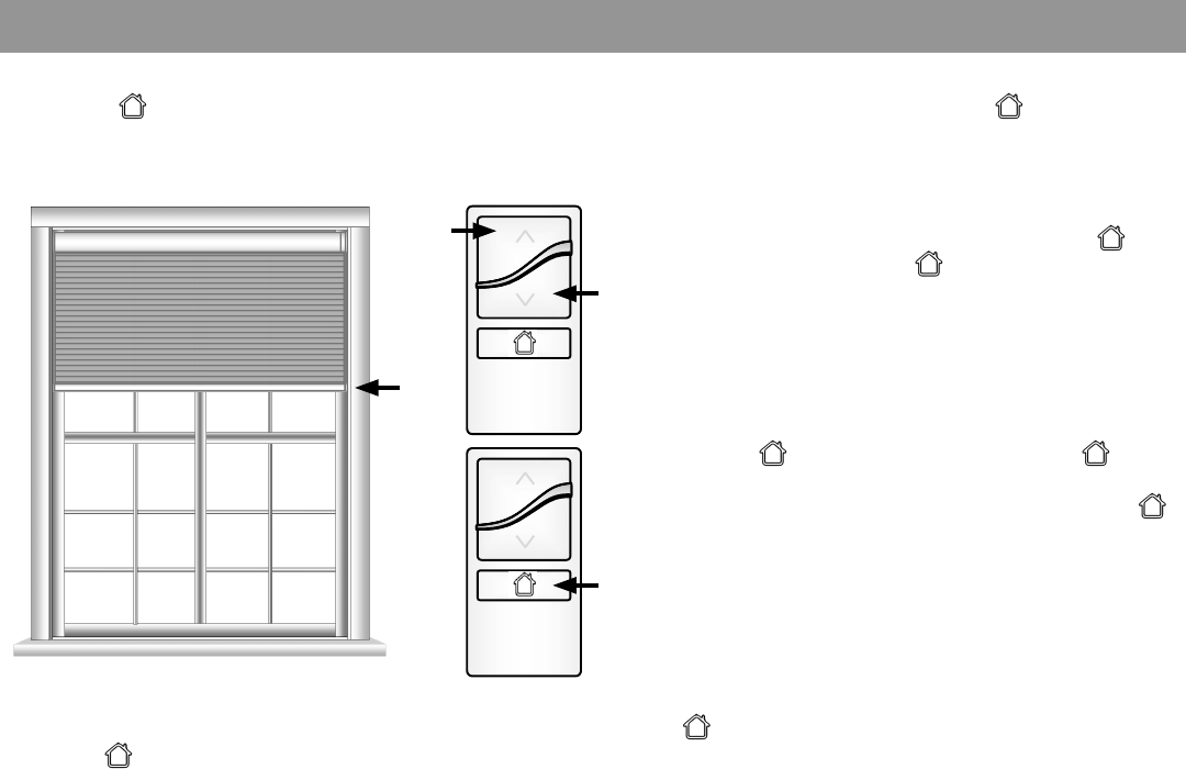
Adjusting Your Shade’s Home Position (optional)
If your shade system includes an optional single-channel remote, it has been pre-programmed to control your shade(s).
The default position (intermediate position) is pre-set to mid-legnth of your shade. To change the position, follow
these steps. Note: if the single-channel remote controls multiple shades as a group, refer to the next section.
Note: Always adjust the upper and lower limits before adjusting your position. After adjusting the upper or lower
limits, the position will reset to the new mid-legnth position.
1. Use the UP or DOWN button to put the shade in
motion. When the shade reaches your desired
position, press and release to stop the shade.
2. To set your position, press and hold the
button until the LED on the remote turns amber, then
release the button. The shade will jog and the new
position is set.
GRA BE R
GRA BE RGRA BE R
8
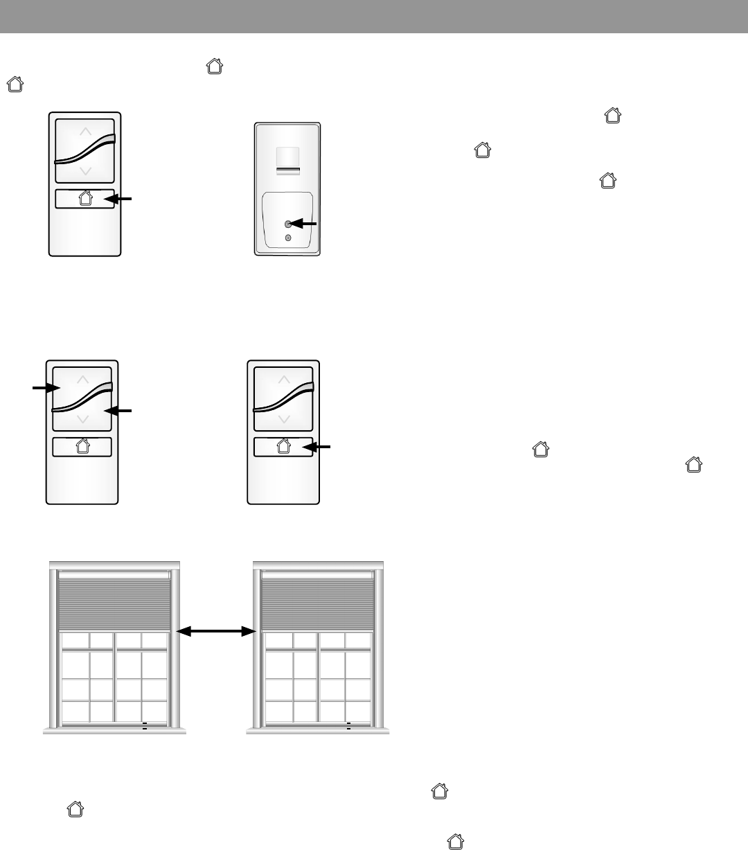
Adjusting the Home Position on a Group of Shades (optional)
If your shade system includes an optional single-channel remote as a group control, it has been pre-programmed to
control your shades. The default position (intermediate position) of all shades is pre-set to mid-legnth. To change the
position on multiple shades, follow these steps.
Note: Always adjust the upper and lower limits before adjusting your position. After adjusting the upper or lower
limits, the position will reset to the new mid-legnth position.
Installer Note: You are required to access the motor head to adjust the position.
1. Press and release the button to bring the
group of shades to their pre-programmed
position.
2. In order to adjust the position of each
shade, you must rst target the individual
shade you want to adjust. To do this, press
and release the back of the single-channel
remote (1 tap). The LED on the remote will
alternattely ash green. Then on the shade
that you want to adjust, press and hold the
program button on the headrail/motor end
until the LED begins to ash green and
release. the shade will jog.
3. Using the two-button remote that controls the
shade, adjust the shade to the new desired
position.
4. Using the single-channel remote, press and
HOLD the button until the LED turns
amber and release the button. The
position of the target shade is now reset.
5. Repeat process for additional shades to
adjust the new desired position.
GRA BE R
GRA BE R
GRA BE R
GRA BE R
9
Each shade is pre-programmed from the factory to operate up and down corresponding to the appropriate buttons on
your Virtual Cord. However, if the directions are inadvertely reversed, follow these steps to return the shade to
proper operation.
All programming steps are associated with a time-out feature to preserve battery life.
Reversing Motor Direction
1. Move the shade to any position between the
upper and lower limits by pressing and
releasing the directional buttons.
The shade will jog and the LEDs on the motor will
begin to blink green and red and the LEDs on the
remote will blink green.
Shade direction has now been reversed; however,
the upper and lower limits have been maintained.
2. Press and hold UP and DOWN buttons
until the LED light turns amber then
release buttons.
3. Press and hold the UP and DOWN buttons
until the LED turns amber then
release buttons.
10
Adding Remotes, Creating Groups and Pairing to Z-Wave Smart Systems
Adding a New Remote When the Only Remote Controlling the Shade is Lost
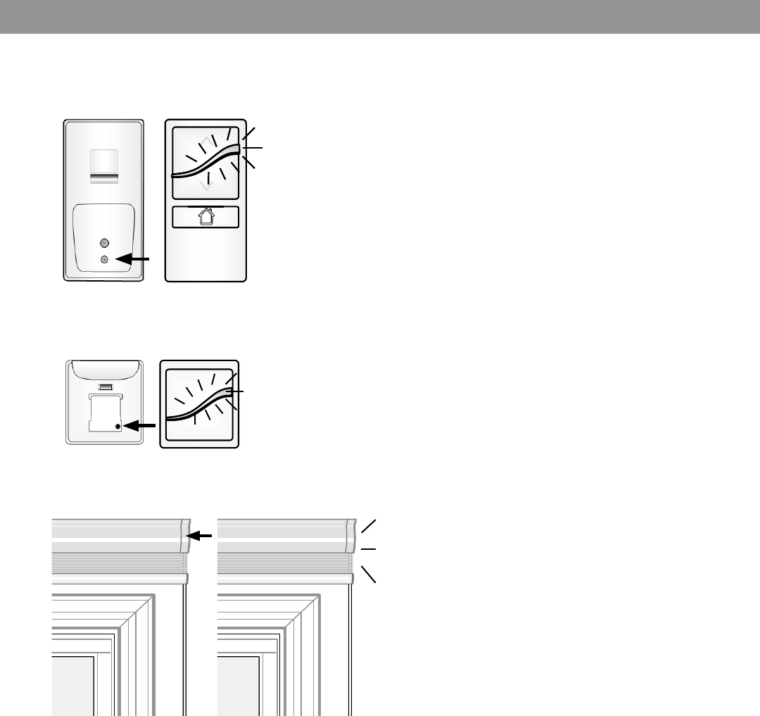
1. Press and hold the program button on the
headrail/motor end, the LED will ash green
then amber. When the shade jogs once,
release the button and the LED will turn solid
amber and turn off. The motor is now ready to
learn a new remote.
2x
Your motorized shades are pre-programmed from the factory with the appropriate pairing and grouping between remotes
and shade motors. There are several scenarios when additional programming steps will be required. The next sections
explain how to accomplish the most common scenarios you will encounter. If the appropriate scenario is not included,
please contact a customer service representative prior to attempting any adjustments.
If you no longer have your remote, or the remote no longer works, follow these steps.
2. Using a paper clip or a similar item, press
and release the programming button located
on the back side of the new remote twice in
rapid succession (two taps within a second
in between). The LED on the remote will ash
alternatively amber and green.
3. Press and hold the program button on the
headrail/motor end until the LED ashes green,
then release the button. This places the motor
into a learning mode for approximately
20 seconds. (LED continues to ash green.)
4. The shade will jog, conrming the motor and
remote are now paired.
GRA BE R
GRA BE R
11
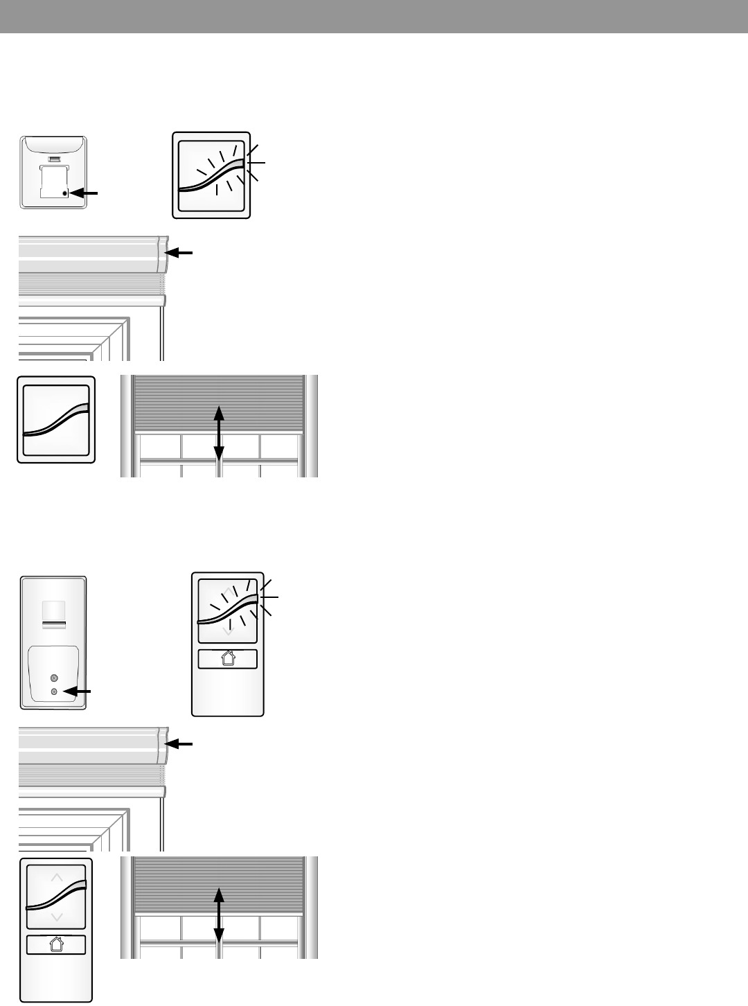
Adding a New Remote as a Group Control
To add a group control to an existing shade, you
must rst clear the current remote(s) from the motors
and remotes.
1. Press and hold the program button on the back
side of the old remotes until the LED turns from
ashing green to ashing amber, then release.
2. At the headrail/motor end, press and hold the
program button until the LED turns from
ashing green to ashing amber. The shade will
jog once, then release.
3. The LED light bar will turn solid green and the
shade will jog, conrming they are now joined.
Include the new remote as the group (primary) control
1. Press and release the program button on the
back side of the new remote twice in rapid
succession (with one second between taps).
2. The LED on the new remote will alternately ash
amber and green to identify inclusion mode.
3. Press and hold the program button on the
headrail/motor end, release when LED
ashes green.
4. The shade will jog and all LED’s will turn off.
5. The shade will now operate from the newly
added remote.
Repeat this process for each remote to be added to
this group.
Associate existing remotes as secondary control.
1. Press and release the program button on the
back side of the primary group remote twice
(with one second between taps).
2. The LED on the primary remote will alternately
ash amber and green to identify inclusion mode.
3. On the existing remote, press and hold the
programming button until the LED begins to ash
green, then release the button.
4. Once the LEDs are off, on the existing remote,
press and release the program button until the
LED begins to alternately ash green.
5. Press and HOLD the program button on the
headrail/motor end until the LED ashes green,
then release the button.
Repeat this process for each remote to be added to
this group.
If a group control was not selected t the time of purchase and is being added to an existing motorized shade, follow the
steps below. Note: Individual shade control will be maintained with the original two-button remote only after it is associ-
ated with the shade (see next page).
GRA BE R
GRA BE R
GRA BE R
GRA BE R
12
Assigning the Single-Channel Remote as Primary
This process is followed when the end user desires to add a single-channel control point for a group of shades as well as
individual control. You must rst exclude all individuals and include the single-channel remote as the primary controller.
Exclude the 2-button as the Primary Controller
1. Triple tap the program button on the back of the
Virtual Cord.
2. The LED light bar on the Virtual Cord will blink, alternating
amber to identify exclusion mode.
3. Press and hold the button on the headrail endcap until the
light begins to blink green (about three seconds).
4. The LED light bar on the remote will turn solid green then
turn off and the shade will jog, conrming exclusion.
Include Single-Channel Remote as the Primary Controller
1. Double tap the program button on the back of the
Virtual Cord.
2. The LED light bar on the single-channel remote will blink,
alternating between amber and green lights to identify
exclusion mode.
3. Press and hold the button on the headrail endcap until the
light begins to blink green (about three seconds).
4. Shade will jog and LED will turn off.
5. The shade will now operate from the
single-channel remote.
3x
2x
GRA BE R
GRA BE R
GRA BE R
GRA BE R
GRA BE R
13
Adding Individual Control Back After Creating a Group
Adding individual control to shades which are part of a newly formed group. This remote will now be referred to as the
secondary control.
Adding a Secondary Controller
1. Starting with the primary control, press and release the
program button on the back side of the current remote
twice in rapid succession (one second between taps).
2. The LEDs will ash alternating amber and green to identify
inclusion mode.
3. Press and hold the program button on the secondary
remote control until the LEDs ash green, then release the
button.
4. Both the primary and secondary remote LEDs will ash
green, then off conrming inclusion.
2x
1x
Hold
Hold
5. The secondary control is now ready for nal steps to
control the shade.
6. Press and release the program button on the back side of
the secondary control once. The LEDs will alternately ash
green.
7. Press and hold the program button on the target shade
headrail or motor end until the LED ashes green, then
release the button.
8. The LED on the secondary control will turn green and the
shade will jog.
9. Both the primary (group) and secondary (individual)
controls will now operate the shade.
Repeat this process on all shades you want to individually
control.
GRA BE R
GRA BE R GRA BE R
14
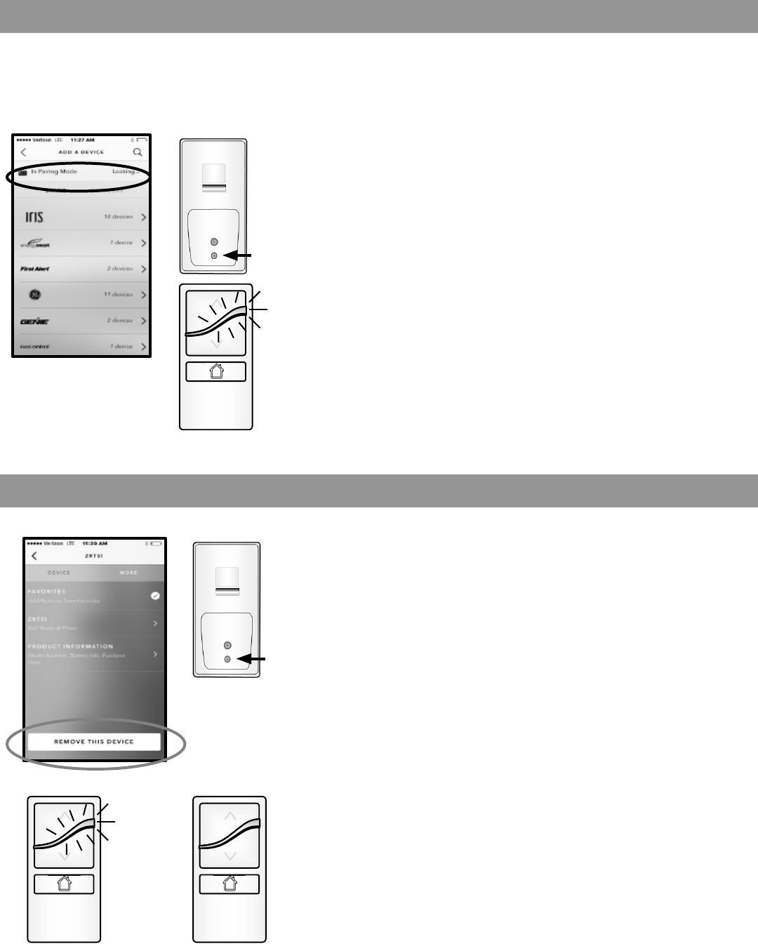
Joining an Existing Z-Wave Network
Removing a Device from a Hub
All shade end limits, controls, and intermediate positions should be programmed prior to joining the network.
1. Place hub into discovery mode (add device). There will be
some form of feedback from the hub that it is searching
for a device.
2. Place single-channel remote in programming mode by
pressing and holding the programming button until the
LED light bar begins to ash green then release
the button.
3. The hub will nd the device.
4. Follow instructions for the system.
1. Place hub into remove device mode (exclude).
2. Press and hold the programming button until the LED light
bar begins to blink green then release the button.
3. LED light bar will turn solid green and turn off.
4. Follow instructions on the hub.
Hold
Hold
15
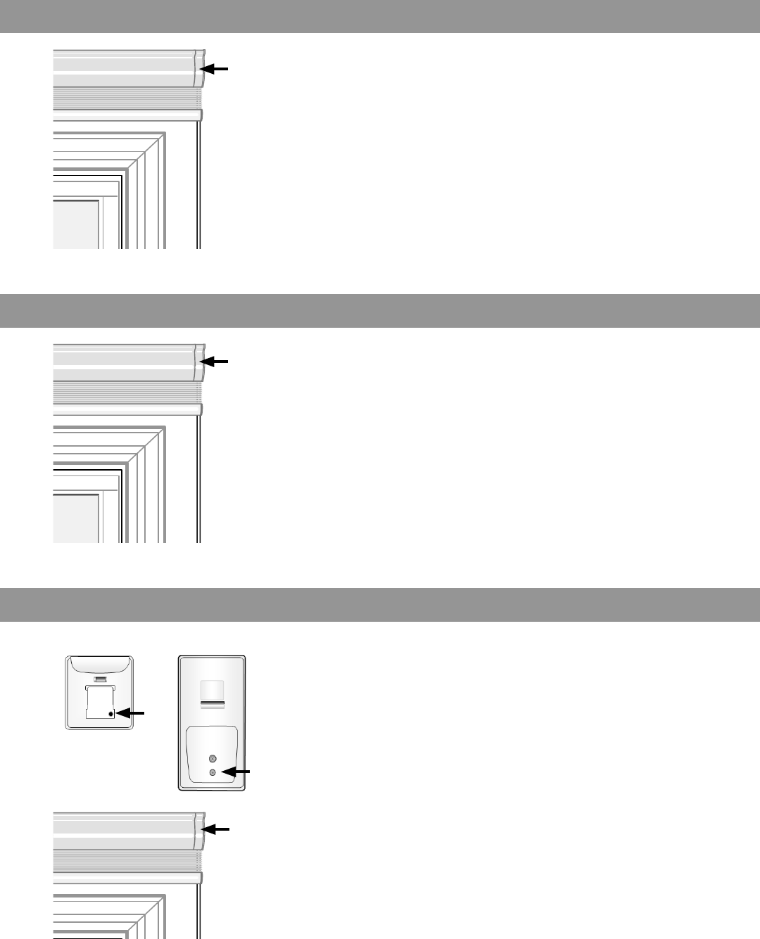
Network Reset
Factory Limits Reset
Local Reset
1. Press and hold the button on the headrail
endcap until the shade jogs once (about 7
seconds), then release the button.
NOTE: Shade limits are not lost.
1. Press and hold the button on the headrail
endcap until the shade jogs twice (about 15
seconds), then release the button.
NOTE: Factory limits are set in the motor at about
2 to 4 inches apart. All controllers will
remain in the motor’s memory.
1. Press and hold the programming button until
the LEDs stop blinking. LEDs will blink green,
amber, red, and then nally turn off (about 15
seconds).
NOTE: Local reset must be performed on both the
controllers and motors.

16
79082-00 (05/16) IMR 16-2677
springswindowfashions.com • Middoleton, WI 53562
Z-Wave is a wireless mesh-networking protocol for reliable, intelligent home control
of all Z-Wave compatible devices. Z-Wave devices can act as repeaters to create a
mesh-network to ensure reliable communication regardless of the manufacturer or
type of device. This product can be included and operated in any Z-Wave network
with other Z-Wave certied devices from any other manufacturer. Z-Wave devices
such as lamp modules, fan controllers, thermostats, dimmer switches and many
other types of home control devices are available from a wide range of
manufacturers The Z-Wave Alliance (www.z-wavealliance.com) provides a list of
manufacturers of Z-Wave compliant devices. Z-Wave was created by Sigma
Designs and more details on the technology can be found at www.z-wave.com.
This product can be included and operated in any Z-Wave network with other
Z-Wave certied devices from other manufacturers and/or other applications. All
non-battery operated nodes within the network will act as repeaters regardless of
vendor to increase reliability of the network.
The current product controls may establish 2 Association Groups. Association
Group #1 is dedicated Lifeline for secondary controls, primarily used for battery
status reports, central scene cc, local reset cc. Association Group #2 is dedicated
to slave shades nodes, with a maximum of 12 slave nodes. Normal shade control
command will use association group #2.
FCC Class B Notice
This device complies with Part 15 of the FCC Rules. Operation is subject to the following two conditions:
1. This device may not cause harmful interference.
2. This device must accept any interference received, including interference that may cause undesired operation.
Note: This equipment has been tested and found to comply with the limits for a Class B digital device, pursuant to Part 15 of
the FCC Rules. These limits are designed to provide reasonable protection against harmful interference in a residential
installation. This equipment generates, uses and can radiate radio frequency energy and, if not installed and used in
accordance with the instructions, may cause harmful interference to radio communications. However, there is no guarantee
that interference will not occur in a particular installation. If this equipment does cause harmful interference to radio or
television reception, which can be determined by turning the equipment off and on, the user is encouraged to try to correct the
interference by one or more of the following measures:
• Reorient or relocate the receiving antenna.
• Increase the separation between the equipment and receiver.
• Connect the equipment into an outlet on a circuit different from that to which the receiver is connected.
• Consult the dealer or an experienced radio/television technician for help.
Modifications: Any modications made to this device that are not approved by Oracle may void the authority granted to the
user by the FCC to operate this equipment.

Springs Window Fashions, LLC
7549 Graber Road
Middleton, WI 53562-1096
Fax (608) 831-2184
Phone (608) 836-1011
USERMANUALADDENDUM
SWFZWaveShadingProducts2016
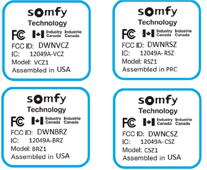
PRODUCTFCCIDENTIFICATION
_________________________________________________________
ModelNumber:CSZ1
Alias:SWFCellularShadeRadioZWave
FCCID:DWNCSZ
IC:12049A‐CSZ
ModelNumber:RSZ1
Alias:SWFRollerShadeRadioZWave
FCCID:DWNRSZ
IC:12049A‐RSZ
ModelNumber:BRZ1
Alias:SWFBasicRemoteControlZWave
FCCID:DWNBRZ
IC:12049A‐BRZ
ModelNumber:VCZ1
Alias:SWFVirtualCordControlZWave
FCCID:DWNVCZ
IC:12049A‐VCZ
Springs Window Fashions, LLC
7549 Graber Road
Middleton, WI 53562-1096
Fax (608) 831-2184
Phone (608) 836-1011
IDLABEL–
LabelMaterial:Yupo60withbackadhesive+GlossyPPCoating

Springs Window Fashions, LLC
7549 Graber Road
Middleton, WI 53562-1096
Fax (608) 831-2184
Phone (608) 836-1011
FCCSTATEMENTS
This portable transmitter with its antenna complies with FCC/IC RF exposure
limits for general population / uncontrolled exposure.
Compliance Statement (Part 15.19)
This device complies with
Part 15 of the FCC Rules.
Operation is subject to the
following two conditions:
1. This device may not cause harmful interference, and
2. This device must accept any
interference received, including
interference that may cause
undesired operation.
Warning (Part 15.21)
Changes or modifications not
expressly approved by the party
responsible for compliance could
void the user’s authority to operate
the equipment.
FCC Interference Statement (Part 15.105 (b)
This equipment has been tested and found to comply with the limits for a Class B
digital device, pursuant to Part 15 of the FCC Rules. These limits are designed to
provide reasonable protection against harmful interference in a residential
installation. This equipment generates uses and can radiate radio frequency
energy and, if not installed and used in accordance with the instructions, may
cause harmful interference to radio communications. However, there is no
guarantee that interference will not occur in a particular installation. If this
equipment does cause harmful interference to radio or television reception, which
can be determined by turning the equipment off and on, the user is encouraged
to try to correct the interference by one of the following measures:
- Reorient or relocate the receiving antenna.
- Increase the separation between the equipment and receiver.
- Connect the equipment into an outlet on a circuit different from that
to which the receiver is connected.
- Consult the dealer or an experienced radio/TV technician for help.

Springs Window Fashions, LLC
7549 Graber Road
Middleton, WI 53562-1096
Fax (608) 831-2184
Phone (608) 836-1011
INDUSTRYCANADASTATEMENTS
Section 7.1.3 of RSS-GEN
This Device complies with Industry Canada License-exempt RSS standard(s).
Operation is subject to the following two conditions: 1) this device may not cause
interference, and 2) this device must accept any interference, including
interference that may cause undesired operation of the device.
Section 7.1.2 of RSS-GEN
Under Industry Canada regulations, this radio transmitter may only operate using
an antenna of a type and maximum (or lesser) gain approved for the transmitter
by Industry Canada. To reduce potential radio interference to other users, the
antenna type and its gain should be so chosen that the equivalent isotropically
radiated power (e.i.r.p.) is not more than that necessary for successful
communication.
DÉCLARATIONSD'INDUSTRIECANADA
Section 7.1.3 DE RSS-GEN
Cet appareil se conforme à la (aux) norme(s) RSS exempte(s) de licence
d'Industrie Canada. Son fonctionnement est soumis aux deux conditions suivantes
: 1) cet appareil ne doit pas causer de l'interférence, et 2) cet appareil doit
accepter toute interférence, y compris l'interférence qui peut causer un
fonctionnement indésirable de l'appareil.
Section 7.1.2 DE RSS-GEN
En vertu des règlements d'Industrie Canada, cet émetteur radio ne peut
fonctionner qu'en utilisant une antenne d'un type et d'une amplification
maximale (ou inférieure) approuvés pour l'émetteur par Industrie Canada. Pour
réduire l'interférence radio potentielle aux autres utilisateurs, le type d'antenne
et son amplification doivent être choisis de manière à ce que la puissance
isotrope rayonnée équivalente (pire) ne soit pas supérieure à ce qui est
nécessaire pour une communication réussie.