Somfy Systems WIREFREE WireFree Eolis Sensor User Manual FCC WireFree Eolis Sensor REV A
Somfy Systems WireFree Eolis Sensor FCC WireFree Eolis Sensor REV A
User Manual

WireFree Eolis Sensor – Preliminary
Part #9013911
I. The Somfy WireFree Eolis sensor (Figure 1) is a battery powered, 2-axis,
vibration sensor that detects vibration of an awning caused by excessive
wind. Upon detecting excessive vibration, the sensor emits an RF signal
to retract the awning. The sensor is bound to an RTS motor as if it were a
Telis transmitter. The sensor is housed in a weather resistant enclosure.
II. Preliminary specifications:
a. Size: 45 mm X 100 mm X 32 mm
b. Lithium Battery Powered, minimum 7-year life. Assumes 50 “Wind
Present” transmissions per day.
c. Range: 50’ open air
III. Mounting considerations: With the awning extended, the sensor must
be mounted either horizontally or vertically; not on an angle. Either end of
the front bar is the preferred mounting location with the awning arms being
a secondary possibility. For proper operation, the awning should be rigidly
mounted to avoid excessive vibration.
a. Horizontally: When mounting horizontally (Sensor A parallel to the
ground) Adjust set point A to setting F and set point B to setting 0.
b. Vertically: When mounting vertically (Sensor B parallel to the
ground) Adjust set point A to setting 0 and set point B to setting F.
IV. Binding Sensor to Motor – Prior to mounting:
a. Set both set points 0
b. Set DIP switches as shown in Figure 2 – Set Up

c. Insert battery
d. Put RTS motor in program mode by depressing the program button
on original transmitter. Motor jogs.
e. Push the program button on the sensor. Motor jogs. The sensor is
now bound to the motor.
f. Set the DIP switches to Run as shown in Figure 3.
g. To test: Depress the program button and verify that the awning
retracts.
V. Mounting: Adjust the set points as described in I. above. Install cover.
Once the location is chosen mount the sensor using self-tapping sheet
metal screws. While mounting the sensor, be certain to have the original
transmitter nearby, as the sensor will most likely send an up command
due to handling.
VI. Operation:
a. There must be two vibration events exceeding the threshold within
15 seconds for the sensor to send an UP command.
b. There is a delay of 4 seconds between the first vibration event and
the sensing of the second vibration event. This is needed to prevent
nuisance trips caused by the awning arms releasing upon start-up
and the awning stopping upon reaching the extended limit.
c. If the awning is fully retracted and a down command is sent, a
subsequent stop or up command sent within 15 seconds will likely
cause the sensor to send an up command.
d. If the awning is started and stopped within 15 seconds from any
position, the sensor will likely send an up command.
e. The sensor requires 10 seconds of calm before it will send a
second signal. This delay prolongs battery life.
f. When the battery is near full discharge, the sensor will send an up
command and shut down.
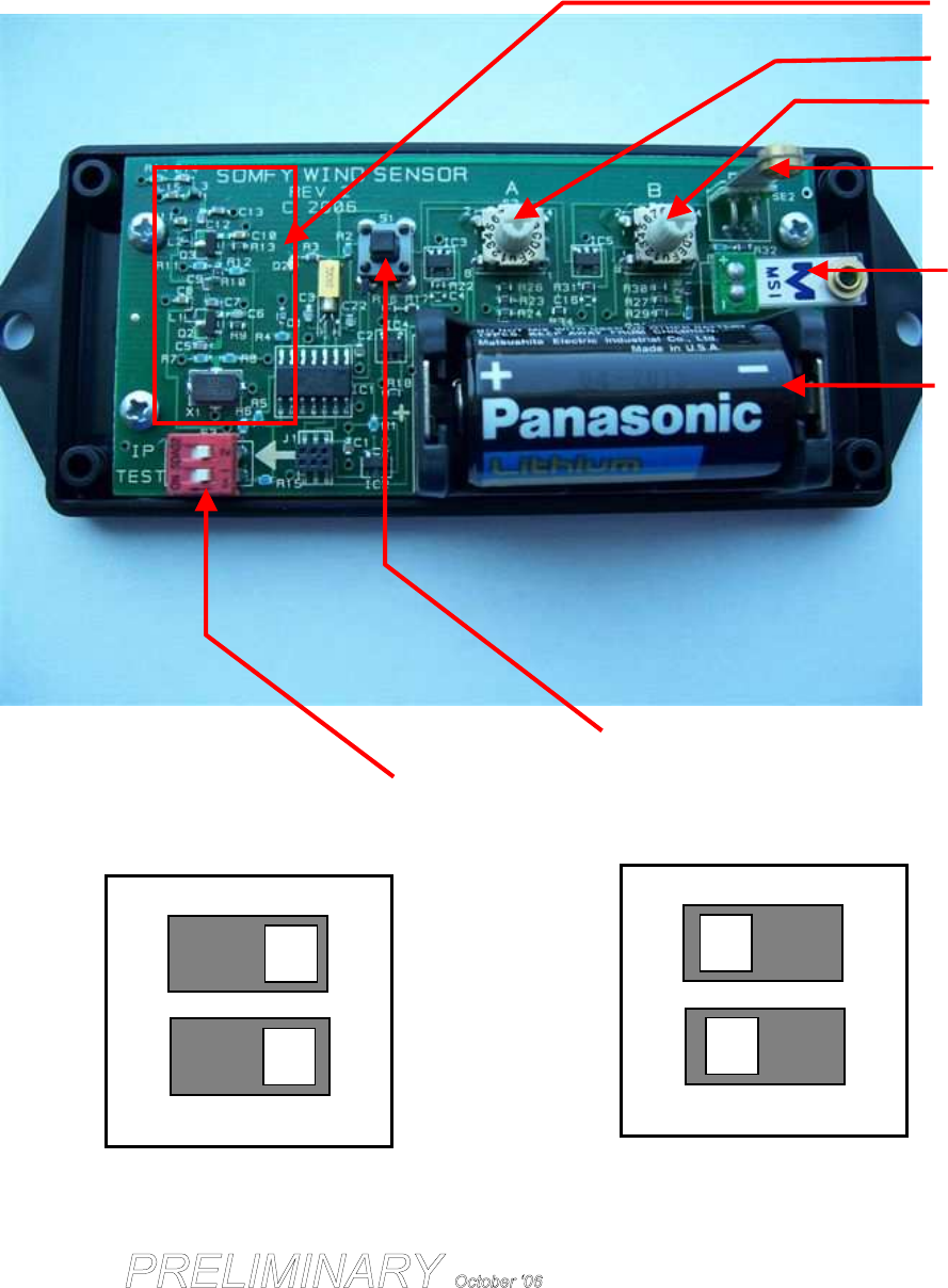
Sensor Component Location and Identification
Figure 1
Sensor for axis B
Mode and Delay Select Dip Switches
RTS Transmitter
Set Point for Axis A
(0=Least sensitive, F=Most)
Set Point for Axis B
Shown set to 0
Enclosure: 45 mm X 100 mm X 32 mm
Battery
RTS Program and Test Button
Sensor for axis A
1
2
Fig. 2 Set
-
Up
1
2
Fig. 3 Run
FCC Information
This device complies with Part 15 of the FCC Rules. Operation is subject to the following two
conditions:
1. This device may not cause harmful interference, and
2. This device must accept any interference received, including interference that
may cause undesired operation.
Warning
Changes or modifications not expressly approved buy the manufacturer could void the user’s
authority to operate the equipment.
Note: This equipment has been tested and found to comply with the limits
for a CLASS B digital device, pursuant to Part 15 of the FCC rules. These
limits are designed to provide reasonable protection against harmful
interference when the equipment is operated in a commercial
environment.
This equipment generates, uses and can radiate radio frequency energy
and, if not installed and used in accordance with the instructions, may
cause harmful interference to radio communications. However, there is no
guarantee that interference will not occur in a particular installation. If this
equipment does cause harmful interference
to radio or television reception,
which
can be determined by turning the equipment off and on, the user is
encouraged to try and correct the interference by one or more of the
following measures:
1.1 Reorient or relocate the receiving antenna.
1.2 Increase the separation between the equipment and receiver.
1.3
Connect the equipment into an outlet on a circuit different from that
to which the receiver is connected.
1.4 Consult the dealer or experienced radio/TV technician for help.