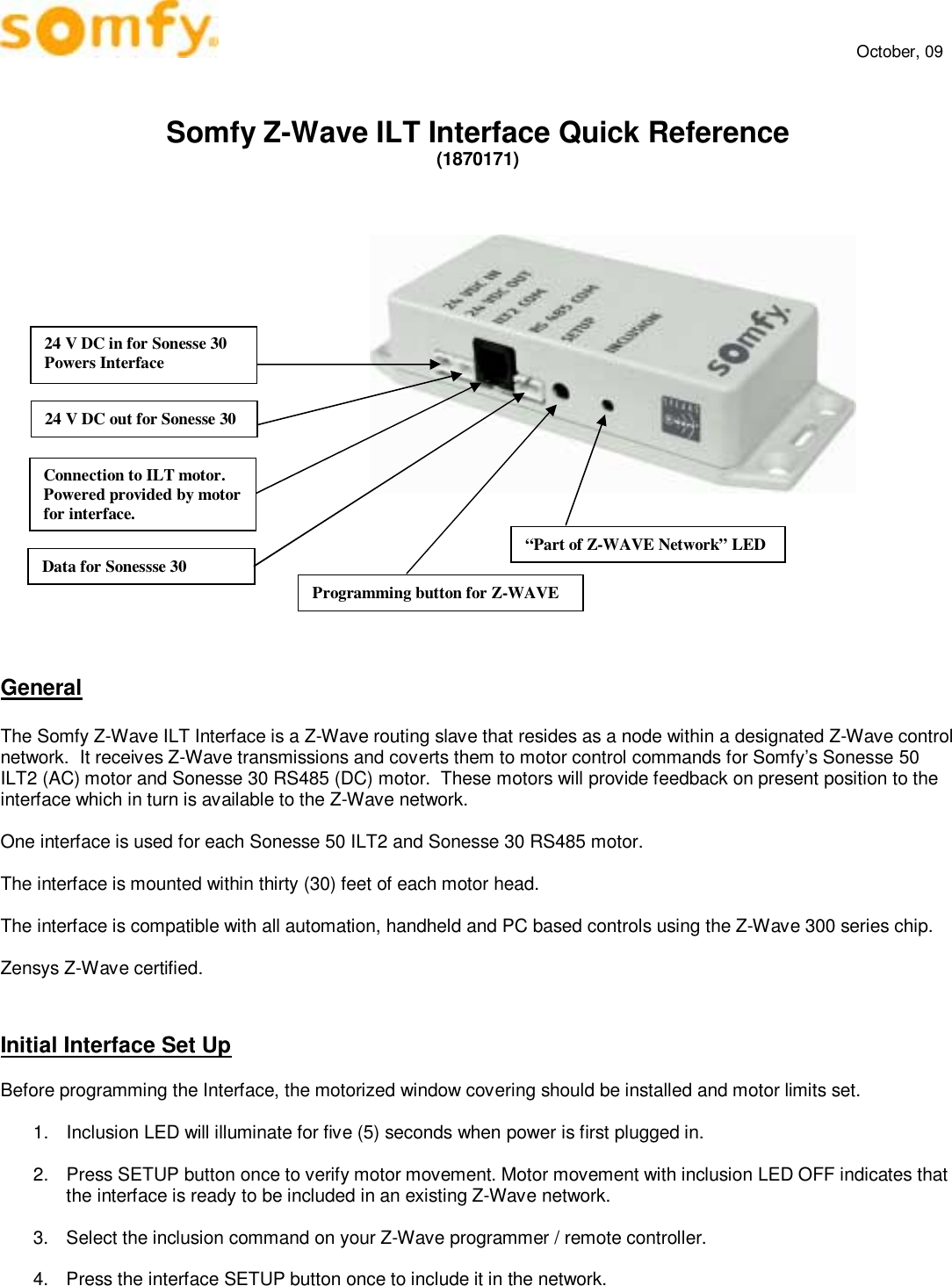
Somfy Systems ZILT Z-wave ILT Interface User Manual

Somfy Systems Z-wave ILT Interface

User manual

    October, 09   Somfy Z-Wave ILT Interface Quick Reference  (1870171)                     General  The Somfy Z-Wave ILT Interface is a Z-Wave routing slave that resides as a node within a designated Z-Wave control network.  It receives Z-Wave transmissions and coverts them to motor control commands for Somfy’s Sonesse 50 ILT2 (AC) motor and Sonesse 30 RS485 (DC) motor.  These motors will provide feedback on present position to the interface which in turn is available to the Z-Wave network.  One interface is used for each Sonesse 50 ILT2 and Sonesse 30 RS485 motor.  The interface is mounted within thirty (30) feet of each motor head.  The interface is compatible with all automation, handheld and PC based controls using the Z-Wave 300 series chip.  Zensys Z-Wave certified.    Initial Interface Set Up  Before programming the Interface, the motorized window covering should be installed and motor limits set.   1.  Inclusion LED will illuminate for five (5) seconds when power is first plugged in.  2.  Press SETUP button once to verify motor movement. Motor movement with inclusion LED OFF indicates that the interface is ready to be included in an existing Z-Wave network.  3.  Select the inclusion command on your Z-Wave programmer / remote controller.  4.  Press the interface SETUP button once to include it in the network.  Connection to ILT motor. Powered provided by motor for interface. 24 V DC in for Sonesse 30 Powers Interface 24 V DC out for Sonesse 30 Data for Sonessse 30 Programming button for Z-WAVE “Part of Z-WAVE Network” LED
    October, 09   5.  The INCLUSION LED will stay illuminated when the interface is included in the network.   Interface Operation  The interface is operated by 3rd party automation, handheld and PC based controllers as if they were controlling a lighting dimmer as per the following examples:  ♦  Light ON = Window Covering DOWN,  Light OFF = Window Covering UP  ♦  Light DIM & BRIGHTEN = Window Covering Opened by Percentage where 0% = Window Covering OPEN at its upper limit and 100% = Window Covering CLOSED at its lower limit.  ♦  Lighting percentage values between 0% and 100%  = 99 intermediate window covering positions  The SETUP button can be used to manually operate the motor.  1.  With the motor stopped, press the SETUP button ONCE and release to start the motor moving to its limit. A second button press and release will reverse the motor direction.    2.  To move the motor to any position within its full travel, press SETUP and wait until the motor is at the desired position and release. If direction is reversed, release SETUP and then press and hold again.  3.  While the motor is moving press the SETUP button ONCE to reverse direction to it’s other limit or the SETUP button could be HELD and released at desired position.          FCC INFORMATION  This device complies with Part 15 of the FCC Results. Operation is subject to the following two conditions:  1. This device may not cause harmful interference, and  2. This device must accept any interference received, including that which may cause undesired operation.  NOTE: This equipment has been tested and found to comply with the limits for CLASS B digital device, pursuant to Part 15 of FCC Rules. These limits are designed to provide reasonable protection against harmful interference when the equipment is operated in a commercial environment.   This equipment generates, uses and can radiate radio frequency energy and, if not installed and used in accordance with the instructions, may cause harmful interference to radio communications. However, there is no guarantee that interference will not occur in a particular installation.   If this equipment does cause harmful interference to radio or television reception, which can be determined by turning the equipment off and on, the user is encouraged to try to correct the interference by one or more of the following measures:  1. Reorient or relocate the receiving antenna 2. Increase the separation between the equipment and receiver 3. Connect the equipment into an outlet on a circuit different from that to which receiver is connected 4. Consult the dealer or experienced radio/TV technician for help.   WARNING  Changes or modifications not expressly approved by the manufacturer could void the user’s authority to operate the equipment.

Navigation menu