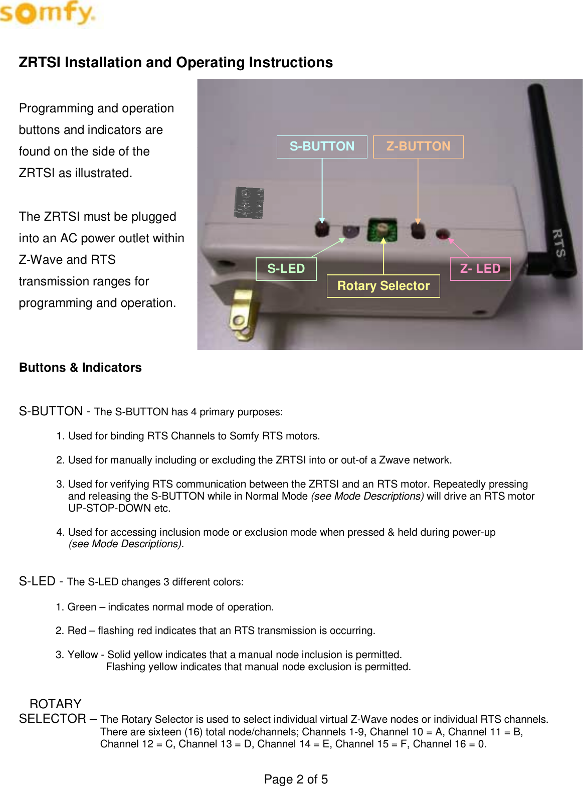
Somfy Systems ZRTSI Zwave to RTS Interface (ZRTSI) Model #1870202 User Manual

Somfy Systems Zwave to RTS Interface (ZRTSI) Model #1870202

User manual

Page 1 of 5    Z-Wave RTS Interface Preliminary Instructions (ZRTSI)  Somfy Part # 1870202     Product Overview The Somfy Z-Wave Universal RTS Interface (“ZRTSI”) is a Z-Wave bridge controller that resides as a secondary controller (only) node within a designated Z-Wave control network.  It receives Z-Wave transmissions and coverts them to motor control commands for Somfy’s full range of RTS wireless controlled motors.  It is recommended that one interface be used for each RTS motor area within a 25-35 foot radius of the interface.  The ZRTSI has sixteen (16) virtual Z-Wave nodes that correspond to sixteen (16) RTS channels.   All nodes can be automatically included with a Somfy TaHoma primary controller #1811151 (or other Z-Wave SIS controllers).  Individual nodes can also be manually included in the network with TaHoma or other standard Z-Wave controllers.  RTS channels are linked to Somfy RTS embedded motors per the RTS programming instructions for each RTS motor type.  The ZRTSI is powered when plugged into an active receptacle.     Z-Wave Certification  ♦  This device is Z-Wave certified pending and can be controlled by all Z-Wave certified controllers.
Page 2 of 5 Z- LED Z-BUTTON   Rotary Selector S-LED S-BUTTON  ZRTSI Installation and Operating Instructions  Programming and operation buttons and indicators are found on the side of the ZRTSI as illustrated.   The ZRTSI must be plugged into an AC power outlet within Z-Wave and RTS transmission ranges for programming and operation.   Buttons & Indicators  S-BUTTON - The S-BUTTON has 4 primary purposes:  1. Used for binding RTS Channels to Somfy RTS motors.  2. Used for manually including or excluding the ZRTSI into or out-of a Zwave network.  3. Used for verifying RTS communication between the ZRTSI and an RTS motor. Repeatedly pressing        and releasing the S-BUTTON while in Normal Mode (see Mode Descriptions) will drive an RTS motor          UP-STOP-DOWN etc.  4. Used for accessing inclusion mode or exclusion mode when pressed & held during power-up                           (see Mode Descriptions).   S-LED - The S-LED changes 3 different colors:  1. Green – indicates normal mode of operation.  2. Red – flashing red indicates that an RTS transmission is occurring.  3. Yellow - Solid yellow indicates that a manual node inclusion is permitted.                               Flashing yellow indicates that manual node exclusion is permitted.      ROTARY  SELECTOR – The Rotary Selector is used to select individual virtual Z-Wave nodes or individual RTS channels.                              There are sixteen (16) total node/channels; Channels 1-9, Channel 10 = A, Channel 11 = B,                Channel 12 = C, Channel 13 = D, Channel 14 = E, Channel 15 = F, Channel 16 = 0.
Page 3 of 5 Z-BUTTON – The Z-BUTTON has 3 primary purposes:  1. Used for manually including the ZRTSI main node to a Zwave network.  2. Used for automatically including (with a SIS controller) all virtual nodes to a ZWave network.  3. Used for resetting the ZRTSI Z-Wave chip to factory defaults when pressed & held together with the      S-BUTTON upon power-up (see Mode Descriptions).   Z-LED - The Z-LED will be on during power-up of the ZRTSI.  If the ZRTSI is included in a network, the LED will                   remain on.  If the ZRTSI is not included in a network, the LED will turn off after 5 seconds. The Z-LED will                   also flash during automatic inclusion of the virtual nodes.   Mode Descriptions   Normal Mode - (also known as Green Mode) – Inserting the ZRTSI into an AC outlet will turn the S-LED green and enable Normal Mode.  This means the ZRTSI is prepared for normal operation or programming.  Normal Mode can also be enabled from Zwave Include or Exclude Modes (see Programming).  Factory Default Mode – With the ZRTSI removed from the AC outlet, press & hold the Z-BUTTON.  While holding the button, insert the ZRTSI into the AC outlet. Continue holding the Z-BUTTON while the Zwave chip and PIC variables are reset (approximately 10 seconds). The LEDs will flash during this time, and when reset is complete the S-LED will be GREEN and the Z-LED will be off. Please note that Factory Default does not reset any RTS programming.  Z-Wave Node Include Mode - (also known as Solid Yellow Mode) – With the ZRTSI removed from the AC outlet, press & hold the the S-BUTTON.  While holding the button, insert the ZRTSI into the AC outlet. Continue holding the  S-BUTTON while Include Mode is being initiated.  The S-LED will flash for approximately 6 seconds during this time, and Include Mode will be enabled when the S-LED is solid yellow.  Release the S-BUTTON after the S-LED turns solid yellow.   Z-Wave Node Exclusion Mode - (also known as Flashing Yellow Mode) – With the Zwave Include Mode enabled  (see above), press & hold the S-Button for approximately 3 seconds until the S-LED begins to flash yellow.  Release the S-BUTTON while the S-LED is flashing yellow.  Factory Default / Include Mode – The ZRTSI can be reset to Factory Default and Node Include Mode in one step if desired.  With the ZRTSI removed from the AC outlet, press & hold the Z -BUTTON and S-BUTTON together.  While holding the buttons, insert the ZRTSI into the AC outlet. Continue holding both buttons while the Zwave chip is reset and  Include Mode is enabled - this may take about 17 seconds.  When the S-LED turns solid yellow, release the buttons.    PROGRAMMING  Add ZRTSI Base Node & ALL 16 Virtual Nodes to a Primary Z-Wave (SIS) Controller Automatically   1.  Verify that the ZRTSI is not included in a Zwave network. 2.  Enable the “Listening Mode” on the SIS controller. 3.  Enable the Zwave Node Include Mode on the ZRTSI. 4.  Press & hold the Z-BUTTON until the Z-LED begins to flash (approximately 3 seconds).  The Base Node      and 16 Virtual Nodes will be added to the SIS controller.  This process may take several minutes, and the        Z-LED will flash rapidly from time to time. The process is complete when the Z-LED stays solid red for 15 seconds or until all 16 virtual nodes appear with your SIS controller.
Page 4 of 5 Add ZRTSI Base Node (Bridge Controller) Only   1.  Verify that the ZRTSI is not included in a Zwave network. 2.  Enable the “Listening Mode” on the SIS controller. 3.  Enable the Zwave Node Include Mode on the ZRTSI. 4.  Press & release the Z-BUTTON. The Z-LED will flash rapidly, then turn solid red when the process is complete.  Add a Z-Wave Virtual Node Manually  1.  Enable the “Listening Mode” on the SIS controller. 2.  Enable the Zwave Node Include Mode on the ZRTSI. 3.  Select the desired RTS channel on the Rotary Selector  4. Press the S-BUTTON for 1 second.        NOTE - If no SIS controller is present, each node, including the main bridge node must be included manually.  Remove a ZWave Virtual Node Manually  1.  Enable the “Listening Mode” on the SIS controller. 2.  Enable the Zwave Node Exclude Mode on the ZRTSI. 3.  Select the desired RTS channel on the Rotary Selector.  4. Press the S-BUTTON for 1 second.  Enable Normal Mode from Include or Exclude Mode  1.  While the ZRTSI is in either Include or Exclude Mode (solid yellow or flashing yellow), press and hold the  S-BUTTON until the S-LED turns Green.  This may take several seconds. 2.  When the S-LED turns Green, Normal Mode is enabled.  Binding an RTS Channel to a Motor  1.  Enable the Normal Mode on the ZRTSI. 2.   Refer to the RTS Motor instructions, and place the RTS Motor into Programming Mode.   3.  Select the desired RTS channel on the Rotary Selector.   4.  Press & hold the S-BUTTON until the S-LED flashes and the RTS motor jogs. The jogging will indicate that the RTS channel has been accepted.  5.  Verify RTS communication between the ZRTSI and the RTS Motor by pressing and releasing the S-BUTTON.  Successively pressing and releasing the S-BUTTON should drive the motor UP-STOP-DOWN-STOP-and so on.
Page 5 of 5 Note:  1.  The ZRTSI is intended for professional installation only. It requires specific configuration tools that are only available to Somfy’s trained distribution. Without these tools, the ZRTS can not be made functional  2. Antenna Specifications ( Part # : G-RAOK10110003-C0026)  a. Omni Directional b.  50 Ohm Impedance c. 1.57 Max Gain    FCC INFORMATION  This device complies with Part 15 of the FCC Results. Operation is subject to the following two conditions:  1. This device may not cause harmful interference, and  2. This device must accept any interference received, including that which may cause undesired operation.  NOTE: This equipment has been tested and found to comply with the limits for CLASS B digital device, pursuant to Part 15 of FCC Rules. These limits are designed to provide reasonable protection against harmful interference when the equipment is operated in a commercial environment.   This equipment generates, uses and can radiate radio frequency energy and, if not installed and used in accordance with the instructions, may cause harmful interference to radio communications. However, there is no guarantee that interference will not occur in a particular installation.   If this equipment does cause harmful interference to radio or television reception, which can be determined by turning the equipment off and on, the user is encouraged to try to correct the interference by one or more of the following measures:  1. Reorient or relocate the receiving antenna 2. Increase the separation between the equipment and receiver 3. Connect the equipment into an outlet on a circuit different from that to which receiver is connected 4. Consult the dealer or experienced radio/TV technician for help.   WARNING  Changes or modifications not expressly approved by the manufacturer could void the user’s authority to operate the equipment.

Navigation menu