Sonim Technologies EU0312 XPi Rugged Device User Manual Title
Sonim Technologies, Inc. XPi Rugged Device Title
UserManual.wiki
>
Sonim Technologies
>
EU0312 User Manual
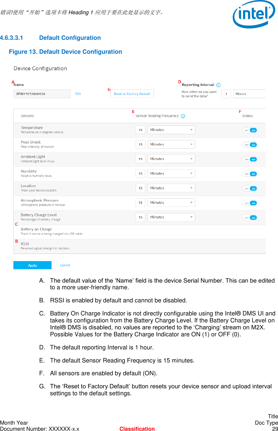
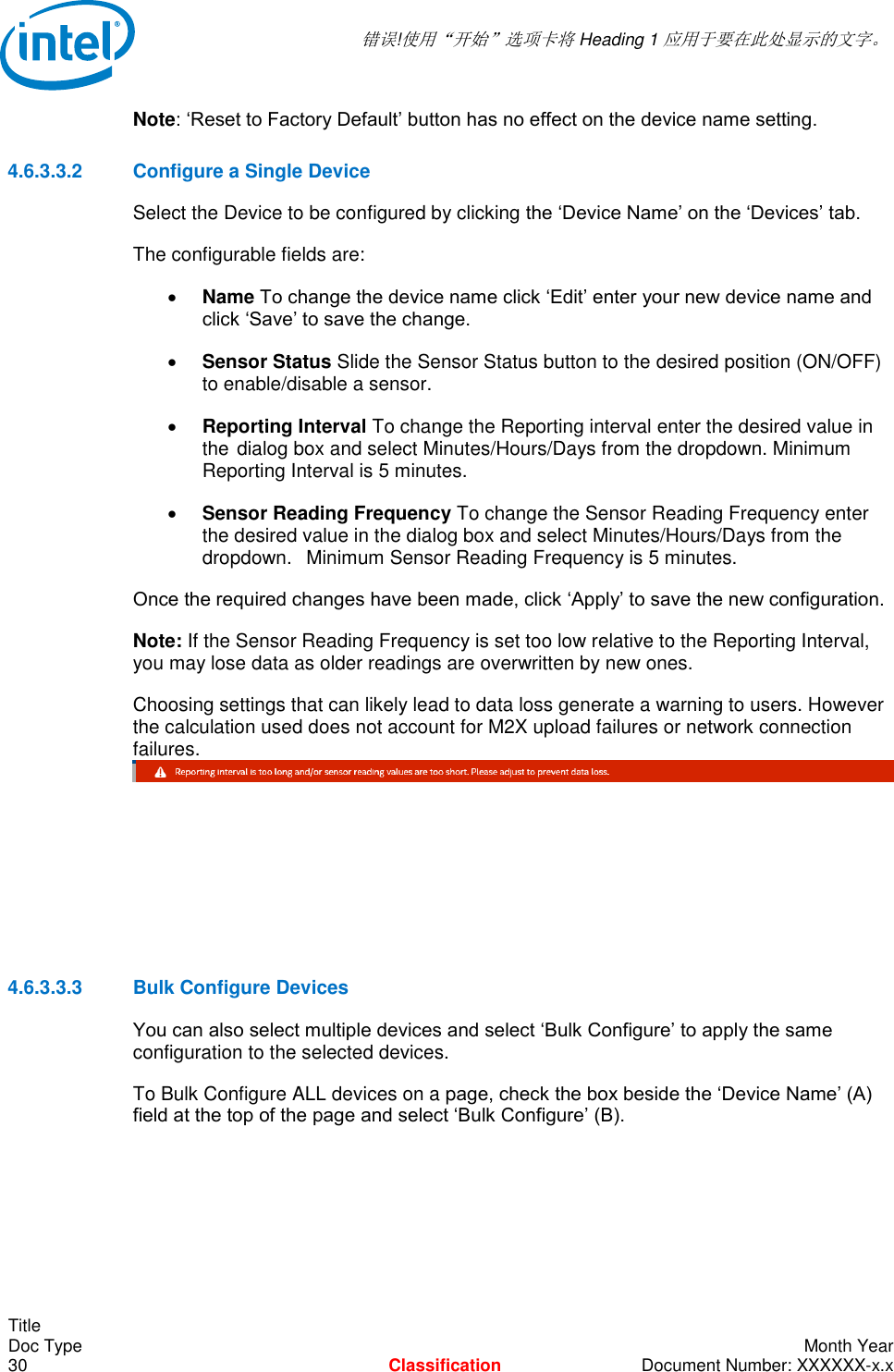
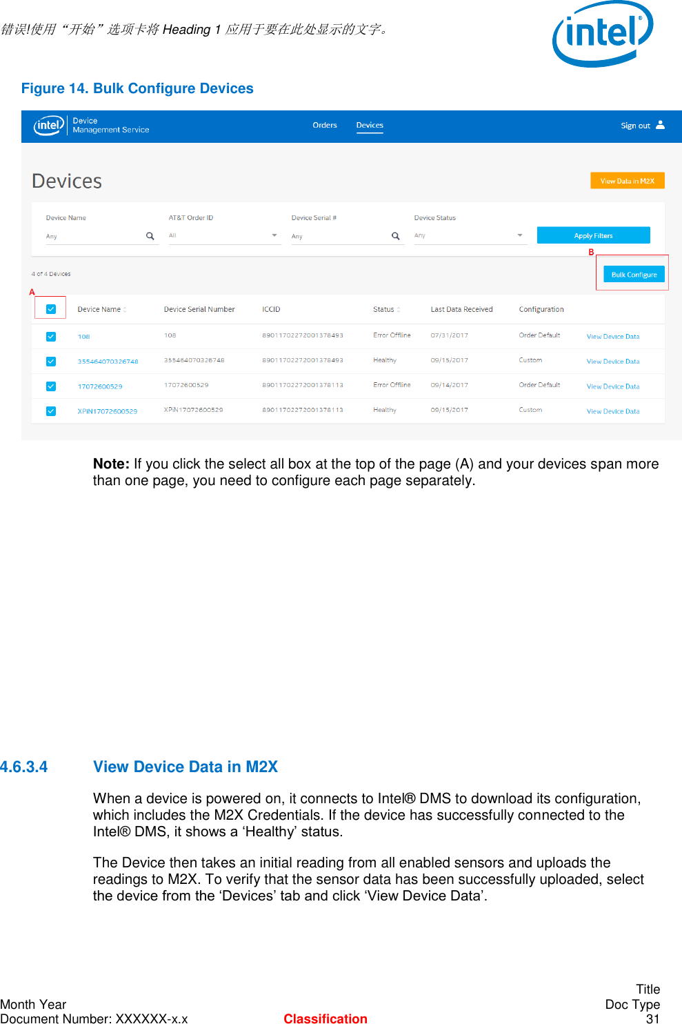
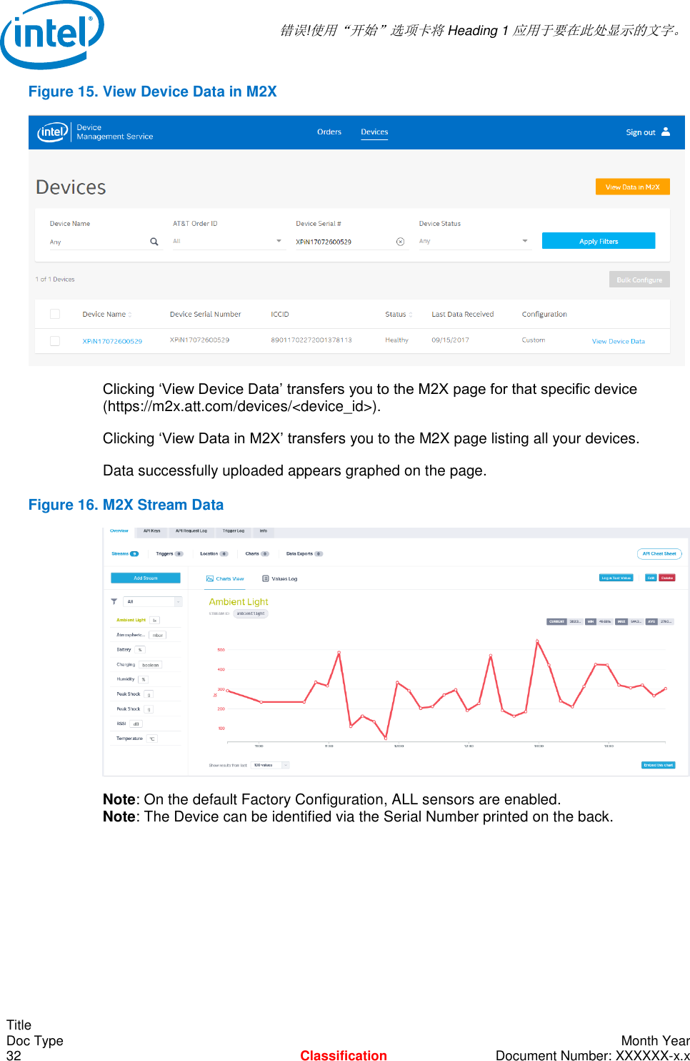
User Manual
Navigation menu
Upload a User Manual
Namespaces
Wiki Guide
HTML
PDF
Info
Views
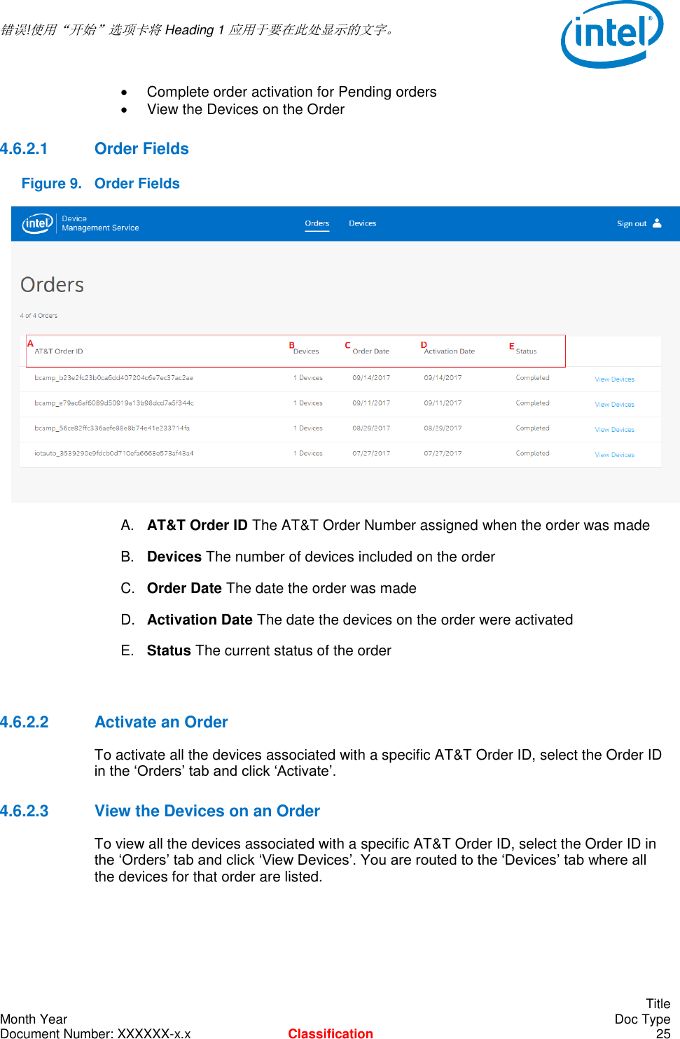
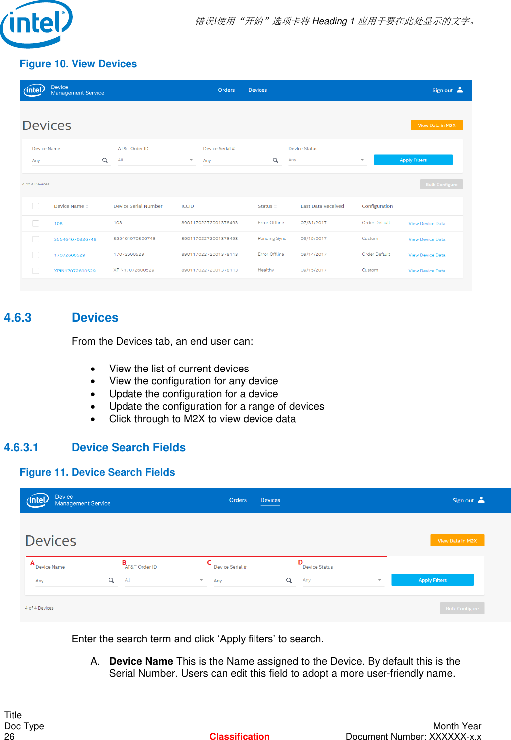
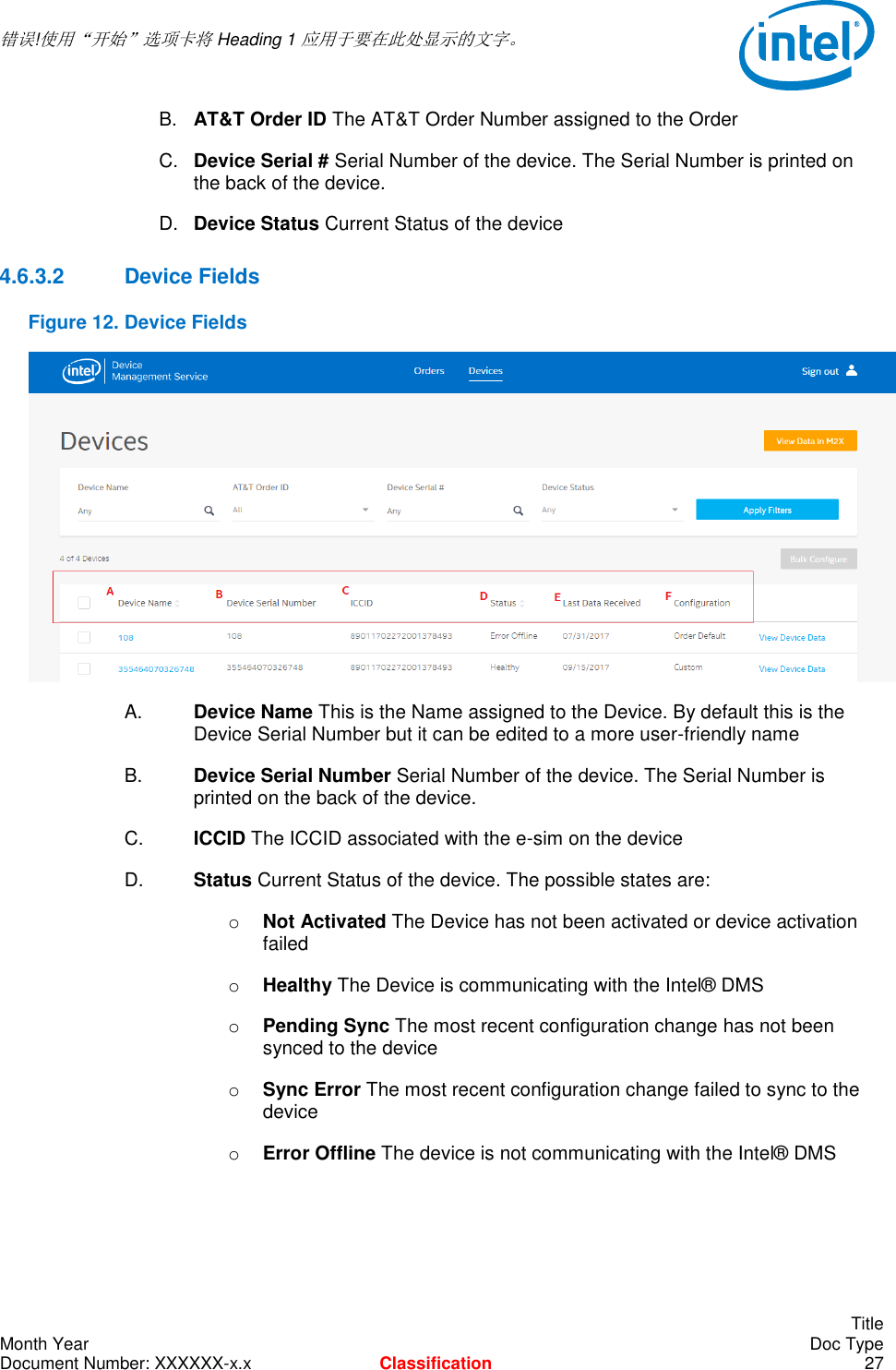
User Manual
Discussion / Help
Navigation