77733 11K IN
77733-11K-In 77733-11K-IN 77733-11K-IN 3072 instructions part uploads sonnax-dev
2014-11-20
: Sonnax 77733-11K-In 77733-11K-IN 1693 file instruction uploads
Open the PDF directly: View PDF ![]() .
.
Page Count: 3
GM 4L60-E, 4L65-E
Smart-Tech®
Input Housing Kit
with Heavy Duty
Input Shaft
Part No.
77733-11K
• Smart-Tech® Input Housing with
300mm Non-Reluctor Style Input
Shaft Assembly
• PTFE Impregnated Rear Stator
Support Bushing
• Overrun Piston Inner Seal
• Overrun Piston
• 3-4 Clutch Apply Plate
• 3-4 Clutch Return Springs (10)
• Bolt-on Anchor Plate
• Overrun Piston Outer Seal
• Socket Head Cap Screws (15)
Patent No. 8,857,592
NOTE: Fits 300mm non-reluctor units
only.
Also Available
Forward Piston Installation Tool
77764-INSTL
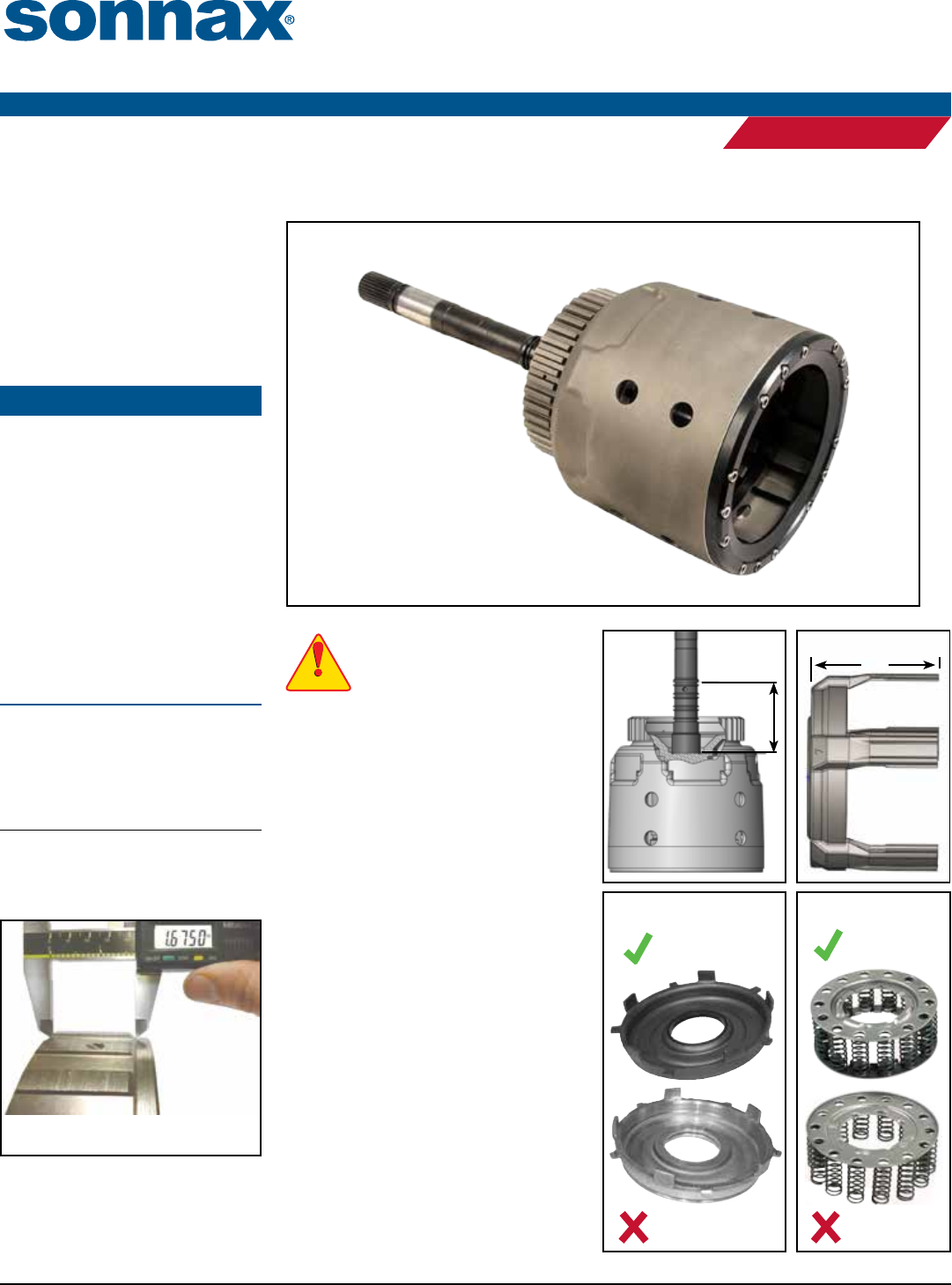
Verify Input Shaft Compatibility
Verify input shaft compatibility by
measuring (Figure 1). Sealing ring
location should be the same as the original
shaft for the application.
Use ‘91-Later Apply Ring
Requires ‘91-later 3-4 apply ring stamped “7”
with dimension "A" of 3.671 to 3.682" (Figure 2).
Use ‘97-Later Ring Gear
Requires ‘97-later ring gear. e correct
spline length is 1.675" (Figure 3).
Use Stamped Steel Forward Piston
is kit must be used with a ‘97-later stamped
steel forward piston (Figure 4). It cannot
be used with aluminum forward piston or
Sonnax billet forward piston 77764-01.
Use Dual-Cage Return Spring
is kit must be used with a '97-later dual-
cage return spring (24206085), identied
by stamped retainer on both ends of the
springs (Figure 5). Although not required,
the ‘96-earlier style return spring is about
10% stronger and preferred for high RPM
applications. To use the early-style return
spring, swap the bottom spring retainer from
a ‘97-later spring onto the ‘96-earlier spring.
WARNINGWARNING
WARNINGWARNING
A
Figure 2
Figure 1
Figure 4
Steel Forward
Piston
Aluminum Forward
Piston
Figure 5
‘97-Later
Dual-Cage
Return Spring
‘96-Earlier
Return Spring
Figure 3
Measure from face of ring gear (left)
to radius at bottom of taper (right).
©2014 Sonnax Industries, Inc. 77733-11K-IN 11-20-14
800-843-2600 • 802-463-9722 • F: 802-463-4059 • www.sonnax.com Page 1
Instructions
HIGH PERFORMANCE TRANSMISSION PARTS
PERFORMANCE
1. Clutch Selection
is kit has approximately 5mm more room to allow for additional clutch
combinations. e recommended combinations are:
• Eight .067" frictions with seven .095" steels
• Nine .062" frictions with eight .077" steels
2. 3-4 Clutch Pack Installation & Assembly
Use normal assembly procedures for pistons, overrun clutches, forward clutches and
input sprag. Sonnax forward piston installation tool 77764-INSTL is available to
assist installing forward piston over installed reenforcement sleeve.
NOTE: A lip seal is included for use with aftermarket gasket and seal kits that do not include
this seal.
a. Install the Sonnax apply plate, ensuring the ve tabs securely t over the OE
3-4 clutch apply ring.
b. Install a friction plate against the face of the Sonnax apply plate.
c. Install a steel plate against the friction plate. Continue alternating plates, ending
with a friction plate on top.
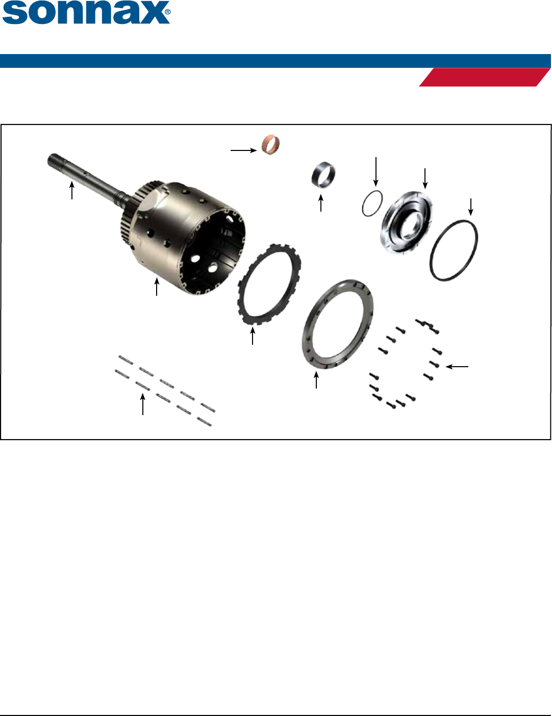
PTFE Impregnated Rear
Stator Support Bushing
Modified Input
Housing
Overrun Piston
Inner Seal
3-4 Clutch
Apply Plate
3-4 Clutch Return
Springs (10)
Bolt-on
Anchor Plate
Socket Head Cap
Screws (15)
Overrun
Piston
Overrun Piston
Outer Seal
Input Shaft
Figure 6
Input Drum
Reinforcement
Sleeve
©2014 Sonnax Industries, Inc. 77733-11K-IN 11-20-14
800-843-2600 • 802-463-9722 • F: 802-463-4059 • www.sonnax.com Page 2
Instructions
HIGH PERFORMANCE TRANSMISSION PARTS
PERFORMANCE
SMART-TECH® INPUT HOUSING KIT WITH HEAVY DUTY INPUT SHAFT 77733-11K
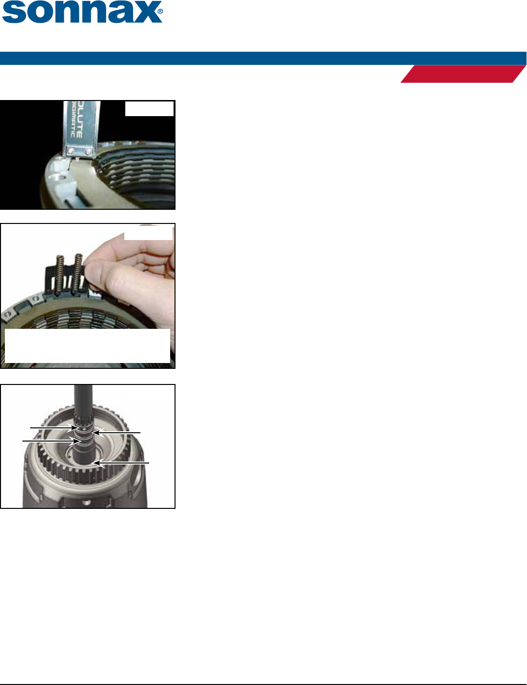
Figure 9
3-4
Feed
Overrun
Feed Forward
Feed
Minimal
Leaks
Figure 7
Orient the spring retainer as shown, with the
free part of the spring facing out and the
retainer towards the O.D. of the housing.
Figure 8
2. 3-4 Clutch Pack Installation & Assembly (continued)
d. With the clutch pack installed, measure the clearance from the top friction to
the end face of the housing. Measure in multiple locations to ensure an accu-
rate reading. Clearance should be between .050" and .060" (Figure 7). Adjust
clearance by substituting dierent thickness steel plates.
e. Install the 10 Sonnax 3-4 clutch return springs into the ve OE spring retain-
ers. ese are required to keep the apply plate released and minimize drag from
the clutches.
f. Slide the spring retainers into the housing, with springs and retainers oriented
as shown (Figure 8).
g. Install the Sonnax bolt-on anchor plate onto input housing, aligning the bolt
holes with the threaded holes in the input housing.
h. To ensure the correct torque spec and thread locking, all threads should be
clean and dry prior to assembly. Apply a drop of Loctite® readlocker 262 or
similar product to the threads of each socket head cap screw. Install all screws
through the backing plate into the threaded housing and lightly tighten each
screw.
i. Torque each fastener to 51 in-lb. Work around the housing in a crisscross (star)
pattern to ensure even pressure on the backing plate.
3. Final Verification Step
Air test assembled housing (Figure 9).
4. PTFE Bushing Installation
a. Remove rear stator bushing, taking care not to damage bushing bore.
b. Install Sonnax PTFE-coated bushing using appropriate driver tool.
©2014 Sonnax Industries, Inc. 77733-11K-IN 11-20-14
800-843-2600 • 802-463-9722 • F: 802-463-4059 • www.sonnax.com Page 3
Instructions
HIGH PERFORMANCE TRANSMISSION PARTS
PERFORMANCE
SMART-TECH® INPUT HOUSING KIT WITH HEAVY DUTY INPUT SHAFT 77733-11K
