77754 03K IN
77754-03K-In 77754-03K-IN 77754-03K-IN 2457 instructions part uploads sonnax-dev
2015-07-02
: Sonnax 77754-03K-In 77754-03K-IN 874 file instruction uploads
Open the PDF directly: View PDF ![]() .
.
Page Count: 4
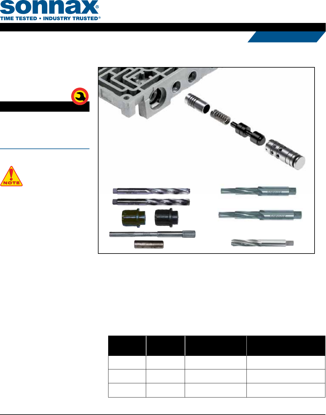
GM 4L60-E, 4L65-E, 4L70-E
TCC Regulator &
Isolator Valve Kit
Part No.
77754-03K
• Isolator Valve
• Spring
• Regulator Valve
• Regulator Sleeve
Patent Nos. 6,990,996 & 7,104,273
NOTE: See "Part Selection" on
this page and "Reaming Options"
on page 2 for usage & tooling
requirements.
R
E
Q
U
I
R
E
D
T
O
O
L
R
E
Q
U
I
R
E
D
T
O
O
L
1. Part Selection
a. There are two TCC regulator valve kit options. Selection is based on the applica-
tion year and TCC apply strategy.
• 77754-04K matches the OE apply rate. It can be used in any application and is
required in ‘98-later vehicles using EC3 apply strategy.
• 77754-03K has an increased apply rate and should only be used in ‘97-earlier vehicles
which do not use EC3 apply strategy, though it can be used in PWM applications.
b. Measure OE Isolator Valve Diameter & Evaluate Isolator Section of Bore for Wear.
OE Isolator
Valve
Diameter
Isolator Bore
Worn?
Use Reaming
Option Install Sonnax Part Number
.441" No Reaming Option A 77754-03K or 77754-04K
.441" Yes Reaming Option B77754-03K or 77754-04K
and 77754-ISO
.473" N/A Reaming Option C77754-03K or 77754-04K
and 77754-ISO
77754-RM5
Required for 77754-ISO
F-77754-TL4 77754-SERV
77754-R2
Regulator
Sleeve
Spring
Regulator
Valve
Isolator
Valve
4L60-E
Valve Body
©2015 Sonnax Industries, Inc. 77754-03K-IN 06-26-15
800-843-2600 • 802-463-9722 • F: 802-463-4059 • www.sonnax.com Page 1
TRANSMISSION PARTS
Instructions
2. Reaming Options
a. Isolator valve was .441" dia.
and isolator bore is not worn:
• Bench Tool option – use
77754-R2
• F-tool option – use
F-77754-TL4 and VB-FIX
b. Isolator valve was .441" dia.
but isolator bore is worn:
• Bench Tool option – use
77754-R2 followed by
77754-RM5
• F-tool option – use
F-77754-TL4 and VB-FIX
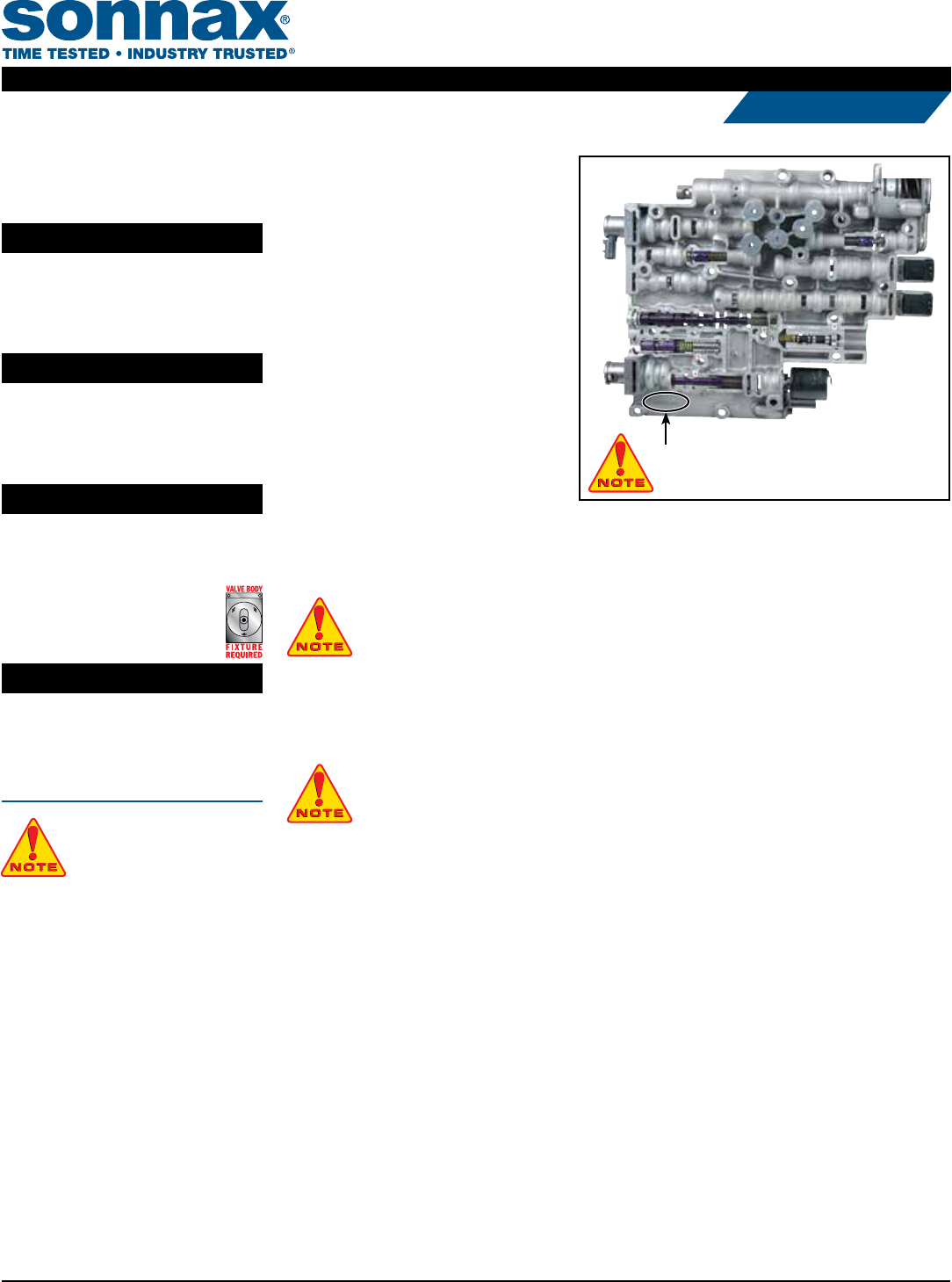
c. Isolator valve was .473" dia. – GM Service valve body (Figure 1):
• Bench Tool option – use 77754-SERV followed by 77754-RM5
• F-tool option – use F-77754-SERV followed by F-77754-TL4, each using VB-FIX
NOTE: Tool kit F-77754-SERV is no longer in production
but may be available from distributor inventory.
3. Disassembly
Remove and discard OE valve train. Save OE retainer for reuse.
4. Reaming Instructions
NOTE: The following reaming instructions are for Bench Tool reaming only (see reaming options
A, B or C above). Reaming directions for F-tool kits that utilize the VB-FIX can be found on
those individual tool kit instructions.
CAUTIONS & SUGGESTIONS:
• Turning the reamer backward will dull it prematurely.
• Pushing on the reamer will result in poor surface nish and inadequate and sporadic material removal.
• Never use a crescent wrench, ratchet or pliers to turn the reamer.
• A dull reamer will cut a smaller hole. Reamers can be sharpened, but should only be done by a profession-
al tool sharpener. Actual life of a Sonnax reamer before resharpening or replacing averages 50-70 bores.
a. Clean bore thoroughly in a solvent tank.
b. Generously lubricate the bore and reamer with cutting uid (i.e. Mobilmet S-122, Lubegard®
Bio-Tap, Tap Magic™, etc.). For best results, provide a continuous ow of cutting uid during
the reaming process.
c. Gently insert the proper reamer into the bore until the cutting tip contacts the rst land to be
reamed. For Bench Tool options A or B, use 77754-R2 for this step. For Bench Tool option
C, use 77754-SERV for this step.
d. Use a loose-tting reamer socket and a wobble adapter to ream the bore. e reamer can
be turned by using a speed handle or with a low-RPM, high-torque drill regulated to a
maximum of 200 RPM. e reaming actions must be clockwise in smooth and continuous
motion at 60-200 RPM. Continue reaming until the reamer stop is reached.
Tool Kits
Part No.
77754-R2
Reamer For Non-Serviced VB
Part No.
77754-SERV
Reamer For GM-Serviced VB
Part No.
77754-RM5
Reamer Use with 77754-ISO
Part No.
F-77754-TL4
• Reamers (2)
• Reamer Jigs (2)
• Guide Pin
• Stop Pin
NOTE: Sonnax “F-Tool” kits
designed to service a specic
bore require the VB-FIX, a
self-aligning valve body reaming xture.
More information and instructions can be
found online at www.sonnax.com.
NOTE: If casting has "SERV" stamped here,
follow reaming option C.
Figure 1
©2015 Sonnax Industries, Inc. 77754-03K-IN 06-26-15
800-843-2600 • 802-463-9722 • F: 802-463-4059 • www.sonnax.com Page 2
TRANSMISSION PARTS
Instructions
TCC REGULATOR & ISOLATOR VALVE KIT 77754-03K, 77754-R2, 77754-SERV, 77754-RM5, F-77754-TL4
4. Reaming Instructions (continued)
e. Using low air pressure, blow the chips free before removing reamer.
f. To remove the reamer, turn clockwise while slowly pulling outward.
g. If performing bench reaming option A, proceed to step 5, "Installation & Assembly". If performing bench reaming option B or C,
repeat steps "a" through "f" with reamer 77754-RM5.
5. Installation & Assembly
a. Ensure valve bore and body is clean and cleared of dirt and debris.
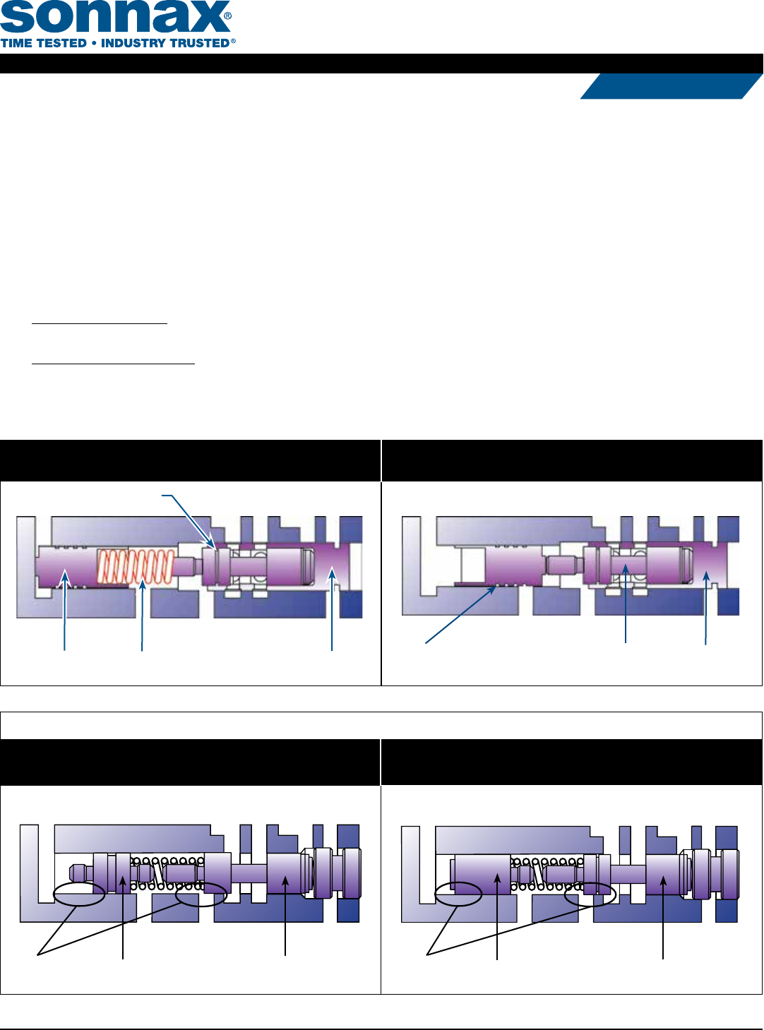
b. Refer to Figures 2 and 3 for correct Sonnax valve train installation lineup. Consult Figures 4, 5 and 6 to determine whether your original
lineup was PWM or non-PWM.
c. For PWM applications: Install Sonnax valve lineup as pictured in Figure 2. Use transjel to retain spring in the isolator valve
during installation.
For non-PWM applications: Install Sonnax valve lineup as pictured in Figure 3.
d. Insert valve/sleeve assembly into the valve body, just deep enough to reinstall OE retaining clip around sleeve.
PWM Valve Lineup
OE ‘98–Later PWM
Common to EC3 controls.
Figure 5
Regulator Valve
Isolator Valve
Wear
OE ‘93–‘97 PWM
Two solenoids at front of body and 13-pin case connector.
Figure 4
Regulator ValveIsolator Valve
Wear
Sonnax Installed Non-PWM
Isolator valve installs with no spring.
Isolator Valve
Install Spring Pocket First Regulator
Sleeve
Regulator
Valve
Figure 2
Sonnax Installed PWM
Figure 3
Isolator Valve Spring Regulator Sleeve
Regulator Valve
©2015 Sonnax Industries, Inc. 77754-03K-IN 06-26-15
800-843-2600 • 802-463-9722 • F: 802-463-4059 • www.sonnax.com Page 3
TRANSMISSION PARTS
Instructions
TCC REGULATOR & ISOLATOR VALVE KIT 77754-03K, 77754-R2, 77754-SERV, 77754-RM5, F-77754-TL4
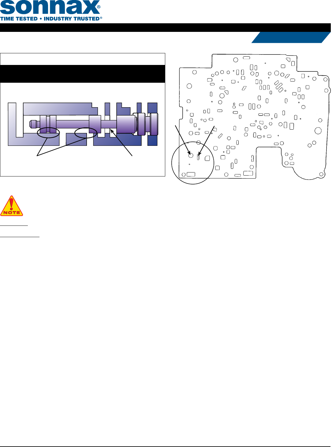
NOTE: Since the castings for PWM and non-PWM valve bodies are identical, this kit can be used when updating a non-PWM valve body for
use in a PWM unit or retrotting a PWM valve body for use in a non-PWM unit. The separator plate must also be changed when this is done
(Figure 7).
PWM plates have “A” & “B” holes (Figure 7).
Non-PWM plates do not have holes “A” & “B” (Figure 7).
One-Piece
Regulator Valve
Wear
Figure 6
OE ‘91–‘94 Non-PWM
One solenoid at front of body and 12-pin case connector.
Non-PWM Valve Lineup
©2015 Sonnax Industries, Inc. 77754-03K-IN 06-26-15
800-843-2600 • 802-463-9722 • F: 802-463-4059 • www.sonnax.com Page 4
TRANSMISSION PARTS
Instructions
TCC REGULATOR & ISOLATOR VALVE KIT 77754-03K, 77754-R2, 77754-SERV, 77754-RM5, F-77754-TL4
AB
Figure 7
