A750E A761E ZIP IN C
2017-08-21
: Sonnax A750E-A761E-Zip-In C A750E-A761E-ZIP-IN_C 3477 instructions part uploads
Open the PDF directly: View PDF ![]() .
.
Page Count: 10
PART NUMBER A750E-A761E-ZIP QUICK GUIDE
1
3
2
* **
6
*
Upper Valve Body #2
Upper Valve Body
Lower Valve
Body #2*
Note: A761 Valve Body Shown.
A750E/F Valve Bodies Vary.
3
2
2
3
*
*
7
6
**
**
2
2
**
Reuse OE Spring
2
*
8
CAUTION! Steps 8 & 9:
Must note locations
of adjustable steps
prior to removal.
See notes on page 2.
10
CAUTION! Note
the location
of OE
checkballs
during disassembly!
Location and quantity
of checkballs varies
depending upon
vehicle application!
Reuse
OE
Spring
2
9
**
Lower Valve
Body
9
*
* A760E/F/H, A761E, A960E/F AB60E/F ONLY
** A750E/F ONLY
3
*
CAUTION! Step 5 must conrm
OE application and sleeve size
rst. See notes on page 2.
2
4
5
©2017 Sonnax Industries, Inc. A750E-A761E-ZIP-Guide_C 08-03-17
800-843-2600 • 802-463-9722 • F: 802-463-4059 • www.sonnax.com Page 1
Toyota/Lexus A750E/F, A760E/F/H,
A761E, A960E/F, AB60E/F ZIP KIT®
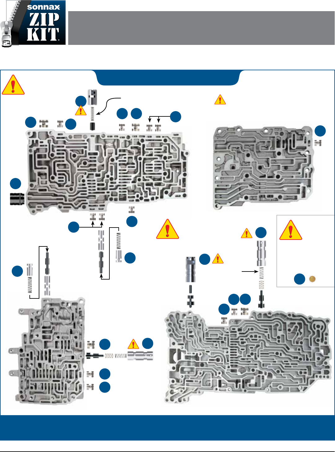
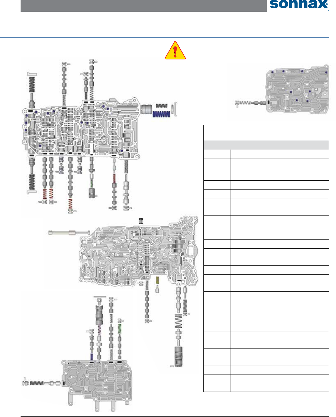
Parts are labeled here in order of installation. See other side of sheet for details on Zip Kit contents.
installation Diagram
In addition to general rebuilding tips and technical information, the technical booklet included in this kit contains vacuum
testing and additional repair options for higher mileage units or for repairing specic complaints which are beyond the
scope of this kit.
Toyota/Lexus A750E/F, A760E/F/H, A761E, A960E/F, AB60E/F ZIP KIT® Quick Guide
FOR STEPS 1–4: Place O-ring in shallow groove. Install end plugs with
O-ring outboard.
Step Replace OE 9mm End Plug
Packaging Pocket 1
• End Plug, 9mm • O-Rings (2) 1 extra
Step
Replace OE 11mm End Plugs
Packaging Pocket 2
• End Plugs, 11mm (9) • O-Rings (15) 6 extra
NOTE: Seven end plugs are used in A750E/F units, while ten end plugs
are used in A760E/F/H & A761E, A960E/F.
Step Replace OE 12mm End Plug
Packaging Pocket 3
• End Plugs, 12mm (3) • O-Rings (4) 1 extra • Bolt (1)
NOTE: Bolt used as tool for installation of threaded end plug into bore
in lower valve body.
Step Replace OE 14mm End Plug
Packaging Pocket 4
• End Plug, 14mm • O-Rings (2) 1 extra
Step Replace OE Lockup Control
Plunger Valve & Sleeve
NOTE: Verify OE application and sleeve OD per chart.
For AB60E/F applications, remove valve from .602" dia sleeve and
install with .616" dia. sleeve. Reuse OE spring with all applications.
Packaging Pocket 5
• Valve/Sleeve Assembly (.602" dia. sleeve) A750E/F, A761E, A960E/F
• Sleeve (.616" dia.) A760E/F/H, AB60E/F
Step Replace OE Solenoid
Modulator Valve Lineup
NOTE: This lineup is in different locations based upon transmission type.
Save OE retainer for reuse. Install Sonnax sleeve/valve assembly with
sleeve end face notches inboard and long valve stem outboard. Install
Sonnax spring over valve stem. Push the end plug in, stepped end rst,
tting the spring into the spring pocket. Secure with OE retainer.
Packaging Pocket 6
• Valve • Sleeve • Spring • End Plug
1
2
3
4
5
6
Step Replace OE B1
Accumulator Piston
NOTE: Save OE springs, cap and retainer for reuse. Install piston,
O-ringed end rst.
Packaging Pocket 7
• Piston • O-Rings (2) 1 extra
Step Replace OE Boost Valve
Assembly
NOTE: Prior to removal, note the position of the adjustable step
on the OE boost sleeve. Reuse OE retainer and make sure it is set
at the same step location on the Sonnax boost sleeve.
Packaging Pocket 8
• Sleeve • Boost Valve • Reverse Boost Valve
Step Replace OE Accumulator
Control Plunger Assembly
NOTE: This lineup is in different locations based upon transmission type.
Packaging Pocket 9
• Plunger Valve • Shims (4) Selective • Sleeve
NOTE: Detailed instructions and illustrations on page 8 of
installation and testing booklet.
Prior to removal, note the position of the OE retaining pin on the step of
the OE castellated plunger sleeve. Save the OE retaining pin and spring
(between valve and sleeve bore) for reuse. Refer to chart for shim assem-
bly details.
After correct number of shims are installed over the long stem of Sonnax
plunger valve, place OE spring over long stem of Sonnax plunger valve.
Install this valve/shim/spring assembly into Sonnax sleeve, spring end
rst. Push assembly into bore and secure with OE retaining pin.
OE Sleeve Notch Pin Location Install This Many Shims
Deepest 0
2nd Deepest 1
Middle 2
2nd Shallowest 3
Shallowest 4
Step Replace OE Checkballs
NOTE: For best results, note location of OE checkballs prior to
valve body disassembly. Checkball quantities and locations vary with
specic valve body applications.
Packaging Pocket 10
Checkballs, .218" dia. (20)
7
8
9
10
Zip Kit Contents & Installation Steps
©2017 Sonnax Industries, Inc. A750E-A761E-ZIP-Guide_C 08-03-17
800-843-2600 • 802-463-9722 • F: 802-463-4059 • www.sonnax.com Page 2
Valve Body
Type
Large Lower
Casting #
Large Upper
Casting #
Small Lower
Casting #
Small Upper
Casting #
Small Lower
Plate Code
Small Upper
Plate Code
Large Plate
Code
A760** 89030 89060 89010 89020 F04 F09 F12
A761 8870 8870 8870 8870 F02 F03 F04
A960 8840 8840 8840 8840 S03 S02 S03
AB60** 89030 89060 89010 89020 F04 L01 L01
S2 S4 SR SL1 SLTS3
SL2 A761E Shown
SLU**
SL1* SLT*
S1
SLU*
SL2*
S2
SR A750E Shown
*Solenoid size, connector color and orientation can vary.
S1
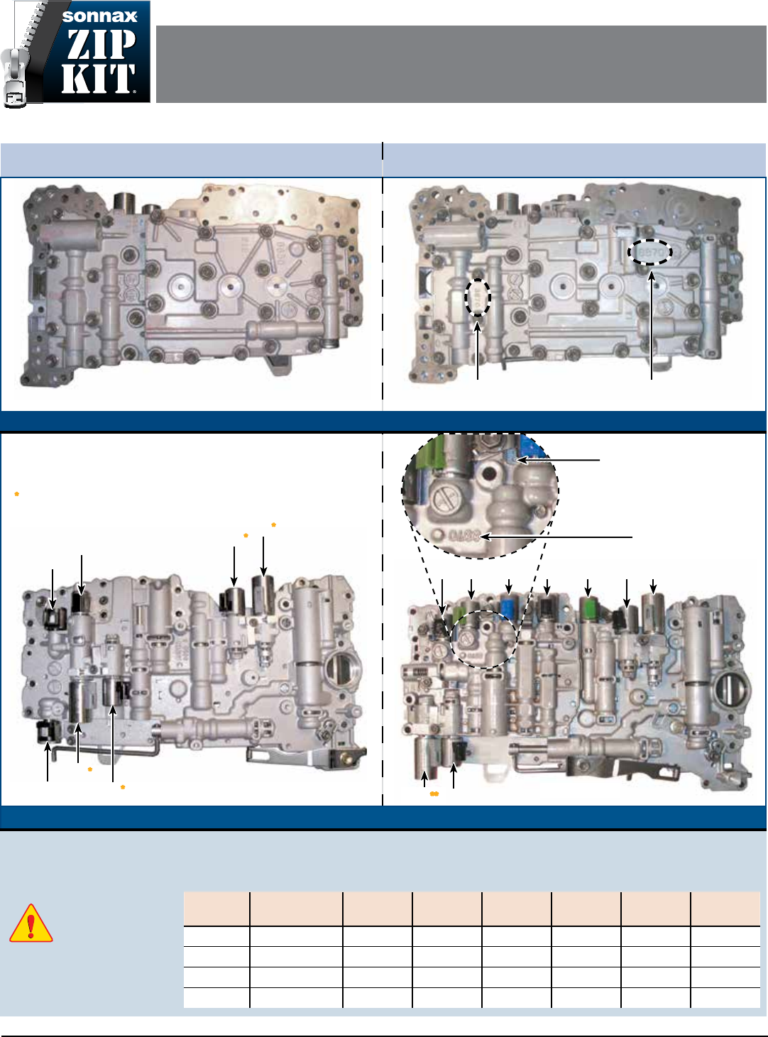
A761E, A960E, A760 & AB60E Valve Body ID
All of the solenoid ID and locations are the same. The only easy way to tell these units apart is the casting numbers.
Proper identication
of this valve body
is critical!
A750 Series 5-Speed, 7 Solenoids A760 Series 6-Speed, 9 Solenoids
A750E Shown A761E Shown
Upper Valve Body
Casting #
Upper Valve Body Cover
Casting #
Upper Valve Body
Lower Valve Body
Lower Valve Body
Casting # Under Solenoid
Lower Valve Body
Casting #
**NOTE: For a quick
identication the SLU connector
is Blue on these models.
Toyota/Lexus A750E/F, A760E/F/H,
A761E, A960E/F, AB60E/F ZIP KIT®
PART NUMBER A750E-A761E-ZIP INSTALLATION & TESTING BOOKLET
©2017 Sonnax Industries, Inc. A750E-A761E-ZIP-Booklet_C 08-03-17
800-843-2600 • 802-463-9722 • F: 802-463-4059 • www.sonnax.com Page 1
Toyota/Lexus A750E/F, A760E/F/H, A761E, A960E/F, AB60E/F ZIP KIT® Installation & Testing Booklet
08-03-17 A750E-A761E-ZIP-Booklet_C ©2017 Sonnax Industries, Inc.
Page 2 800-843-2600 • 802-463-9722 • F: 802-463-4059 • www.sonnax.com
TIME TESTED • INDUSTRY TRUSTED
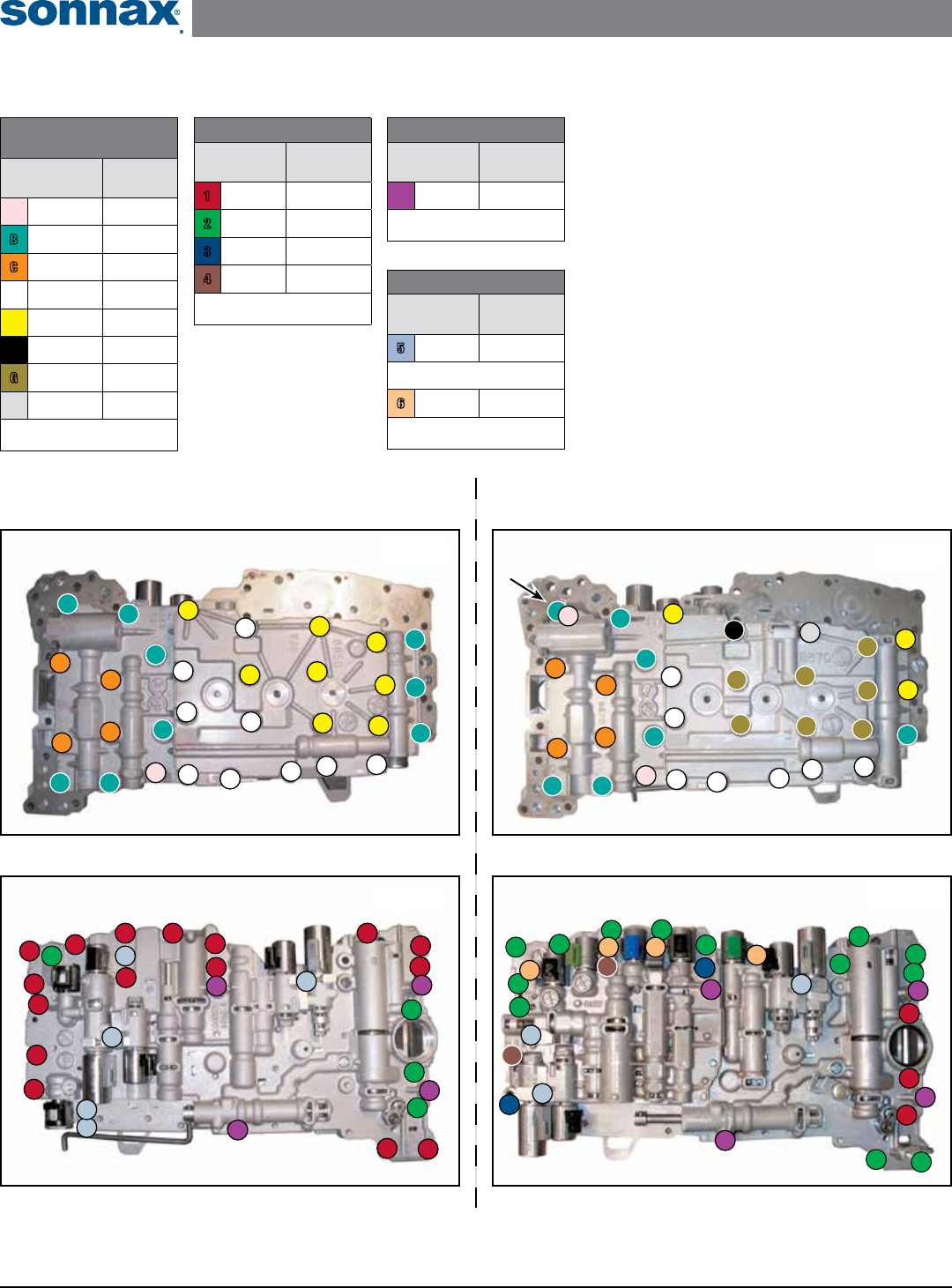
A760 & A960 Series Valve Bodies
(A761E shown)
Valve Body to Case Bolts
Bolt Color
Code
Bolt
Length
1Red 25mm
2Green 36mm
3Blue 45mm
4Brown 50mm
Torque to 8 ft-lb
Oil Filter Bolts
Bolt Color
Code
Bolt
Length
7Purple Various
Torque to 7 ft-lb
Solenoid Bolts
Bolt Color
Code
Bolt
Length
5Lt. Blue 11.5mm
Torque above to 57 in-lb
6Peach 12mm
Torque above to 7 ft-lb
Valve Body
Disassembly Bolts
Bolt Color
Code
Bolt
Length
APink 20mm
BTeal 25mm
COrange 32mm
DWhite 40mm
EYellow 45/50mm
FBlack 60mm
GOlive 64mm
HGray 76mm
Torque to 57 in-lb
Bolt Locations & Torque Specications
Lower Valve Body, Case Removal - Bolt Locations
Figure 2
1
1
1
1
1
1
1
1
1
1
1
1
1
1
1
2
2
2
2
1
7
7
5
5
5
5
5
7
7
Upper Valve Body, Valve Body Disassembly - Bolt Locations
Figure 1
B
B
B
B
B
B
B
B
A
B
D
D
D
D
D
D
D
D
D
C
E
C
C
C
E
E
E
E
E
E
E
Lower Valve Body, Case Removal - Bolt Locations
Figure 4
1
1
1
22
2
2
22
22
2
2
2
2
2
3
3
4
4
7
7
7
7
5
5
5
6
6
6
6
Upper Valve Body, Valve Body Disassembly - Bolt Locations
Figure 3
D
D
D
D
D
D
D
A
B
B
B
B
B
B
B
C
C
C
C
E
G
G
G
G
G
G
G
F
E
E
H
A750 Series Valve Bodies
(A750E shown)
Reset Memory
e Engine Control Module (ECM) in these transmis-
sions adapts to the conditions of the engine and trans-
mission assemblies. When replacing the engine, trans-
mission, valve body or the ECM you must reset the
memory so that the ECM can adapt to new conditions.
Follow OE procedures to reset the memory. Afterwards,
follow the OE road test procedures.
Flex Lockup Clutch Control
e ECM regulates the SLU solenoid to provide an
intermediate mode between the On/O operation of
the converter clutch in the low-to-mid-speed range.
is is for improved fuel economy. Lockup control is
prohibited if the brake is depressed, the accelerator pedal
is released or engine coolant temperature is below 140°F.
A
NOTE: This bolt location varies
• A760 Series = 25mm
• A960 Series = 20mm
Toyota/Lexus A750E/F, A760E/F/H, A761E, A960E/F, AB60E/F ZIP KIT® Installation & Testing Booklet
©2017 Sonnax Industries, Inc. A750E-A761E-ZIP-Booklet_C 08-03-17
800-843-2600 • 802-463-9722 • F: 802-463-4059 • www.sonnax.com Page 3
TIME TESTED • INDUSTRY TRUSTED
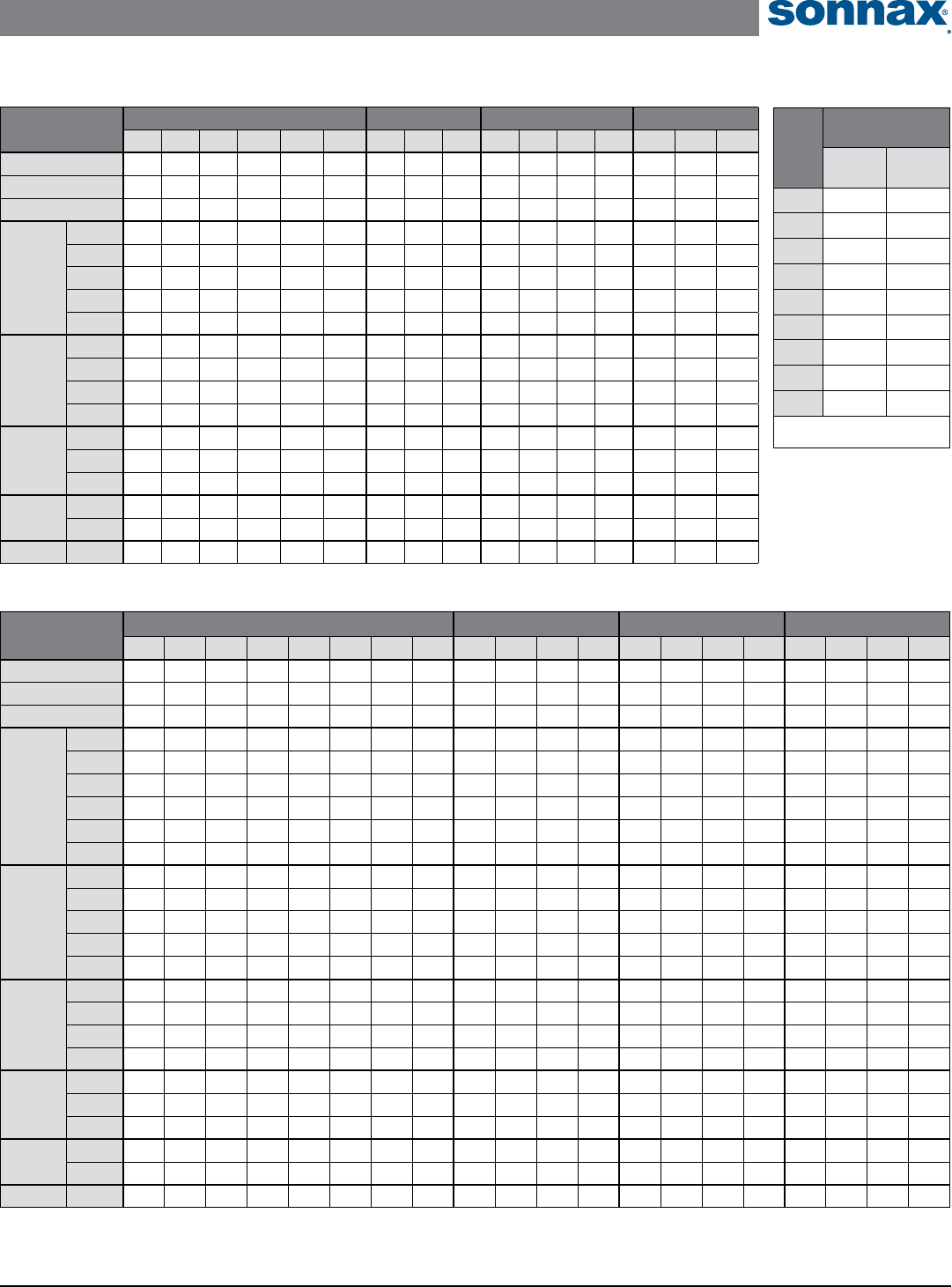
Selector Position Solenoid Valve Clutch Brake One-Way Clutch
S1 S2 SR SL1 SL2 SLU C1 C2 C3 B1 B2 B3 B4 F1 F2 F3
P-Park ON ON
R-Reverse* ON ON
N-Neutral ON ON
Drive
S5
1st ON ON
2nd ON ON ON
3rd ON ON -
4th* ON - -
5th* ON ON ON -
Drive
S4
1st ON ON
2nd ON ON ON
3rd ON ON -
4th* ON ON - -
Drive
S4
1st ON ON
2nd ON ON ON
3rd* ON -
Drive
S2
1st ON ON
2nd* ON ON ON
S1 1st* ON
Figure 5
A750E/F Component & Solenoid Apply Solenoids
Solenoid
Resistance
Ohms
A750
Series
A760
Series
S1 11-15 11-15
S2 11-15 11-15
SR 11-15 11-15
SL1 6 5.0-5.6
SL2 6 5.0-5.6
SLU 6 5.0-5.6
SLT 6 5.0-5.6
S3 –11-15
S4 –11-15
Test all at 68F
Figure 6
Selector Position Solenoid Valve Clutch Brake One-Way Clutch
S1 S2 S3 S4 SR SL1 SL2 SLU C1 C2 C3 C4 B1 B2 B3 B4 F1 F2 F3 F3
P-Park ON ON ON ON
R-Reverse* ON ON ON ON
N-Neutral ON ON ON ON
Drive
S6
1st ON ON ON ON
2nd ON ON ON ON ON ON
3rd ON ON ON ON ON -
4th ON ON ON ON - -
5th ON ON ON ON - -
6th ON ON ON ON ON - --
Drive
S5
1st ON ON ON ON
2nd ON ON ON ON ON ON
3rd ON ON ON ON ON -
4th ON ON ON ON - -
5th ON ON ON ON - -
Drive
S4
1st ON ON ON ON
2nd ON ON ON ON ON ON
3rd ON ON ON ON ON -
4th* ON ON ON ON - -
Drive
S3
1st ON ON ON ON
2nd ON ON ON ON ON ON
3rd* ON ON ON ON -
Drive
S2
1st ON ON ON ON
2nd* ON ON ON ON ON ON
S1 1st* ON ON ON
Figure 7
A760, A960 & AB60 Series Component & Solenoid Apply
CHART KEY:
= In operation.
- = Applied but ineffective.
= Operates during engine
braking.
* = Engine braking occurs
Toyota/Lexus A750E/F, A760E/F/H, A761E, A960E/F, AB60E/F ZIP KIT® Installation & Testing Booklet
08-03-17 A750E-A761E-ZIP-Booklet_C ©2017 Sonnax Industries, Inc.
Page 4 800-843-2600 • 802-463-9722 • F: 802-463-4059 • www.sonnax.com
TIME TESTED • INDUSTRY TRUSTED
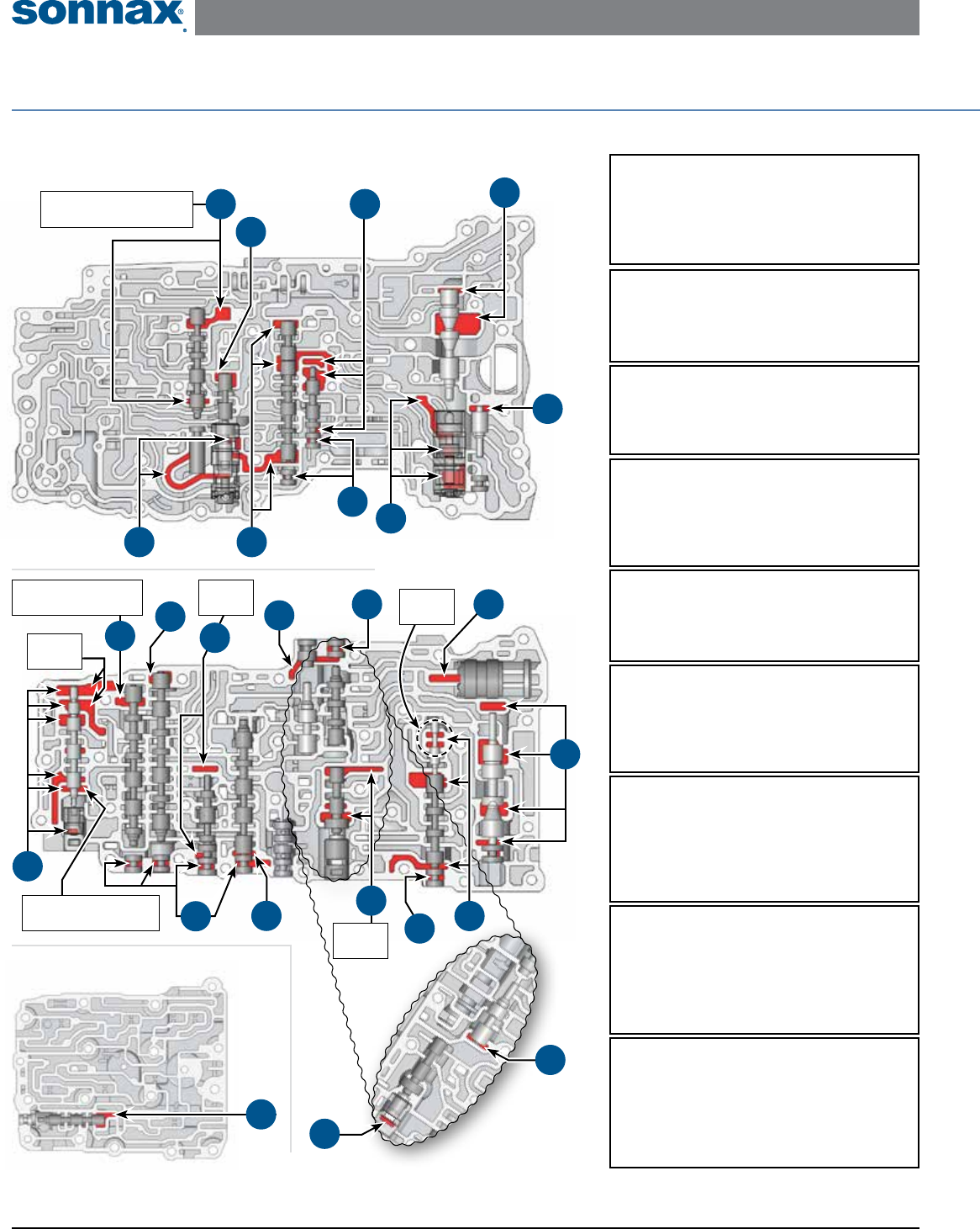
Critical Wear Areas & Vacuum Test Locations
NOTE: OE valves are shown in rest position and should be tested in rest position unless otherwise indicated. Test locations are pointed to with an arrow.
Springs are not shown for visual clarity. Low vacuum reading indicates wear and Sonnax parts noted for replacement.
A750 Series • Lower Valve Body
*Part numbers with an asterisk (*) are included in this Zip Kit. Other part numbers are available separately.
1. Primary Regulator Valve
• Low/High line pressure • Clutch & band failures
• Soft/Harsh shifts • Low converter pressure
Replace with Sonnax Part No. 147741-04K
Requires F-147741-TL4 & VB-FIX
2. Boost Assembly
• Insufcient line rise • Soft/Harsh shifts
• High Reverse pressure • Clutch & band failures
Replace with Sonnax Part No. 147741-01K*
3. Lockup Relay Valve
• TCC apply & release concerns/codes
Replace with Sonnax Part No. 147741-07K
Requires F-147741-TL7 & VB-FIX
5. B1 Accumulator Piston
• 4-5 Shift complaints (A750 Series)
• 4-5, 5-6 Shift complaints (A760 Series)
Replace with Sonnax Part No. 57917E-19K*
6. Solenoid Modulator Valve
• Solenoid codes • TCC slip cycling
• Shift complaints • Low cooler ow
Replace with Sonnax Part No. 147741-05K
Requires F-147741-TL5 & VB-FIX
4. Secondary Regulator Valve
• TCC apply & release concerns
• Harsh lockup • Lube failures
Replace with Sonnax Part No. 147741-10K
Requires F-147741-TL4 & VB-FIX
7. Clutch Control Valve
• Harsh up/down shifts • Flare shifts
Replace with Sonnax Part No.
147741-22K A750 Series
147741-14K A760 & A960 Series
Requires F-147741-TL22 or F-147741-TL14 & VB-FIX
8. Lockup Control Valve
• Harsh downshifts • RPM surge on coast
Replace with Sonnax Part No.
147741-16K A750, A761 & A960 Series
157740-16K A760 & AB60 Series
Requires F-147741-TL16 or F-157740-TL16 & VB-FIX
9. Lockup Control Plunger
Valve & Sleeve
• Harsh downshifts • RPM surge on coast
Replace with Sonnax Part No.
147741-37K A750, A761 & A960 Series
157740-37K A760 & AB60 Series
10
11
21
7
1
2
16
15
25
Upper Valve Body No. 2
Upper Valve Body
24
15
19
Seal port
on back.
Block valve outboard with
.218" dia. checkball.
17
Block valve outboard with
.218" dia. checkball.
Seal port
on back.
12
18
4
5
Test
together.
15
23
Seal port
on back.
8
15
3
Inset: View of reverse
side of upper valve
body. Similar location
on A760 series.
6
9
Block valve outboard with
.218" dia. checkball.
22
Toyota/Lexus A750E/F, A760E/F/H, A761E, A960E/F, AB60E/F ZIP KIT® Installation & Testing Booklet
©2017 Sonnax Industries, Inc. A750E-A761E-ZIP-Booklet_C 08-03-17
800-843-2600 • 802-463-9722 • F: 802-463-4059 • www.sonnax.com Page 5
TIME TESTED • INDUSTRY TRUSTED
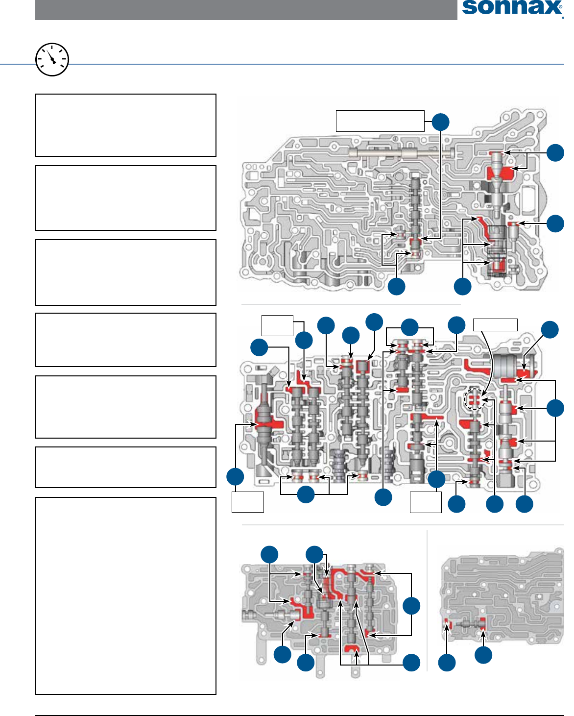
For specic vacuum test information, refer to individual part instructions included in kits and available at www.sonnax.com.
20
25
15
0
10
5
30
VACUUM
TEST
11. Accumulator Control
Plunger Valve & Sleeve
• Shift concerns • Harsh shifts
• Shift codes
Replace with Sonnax Part No. 147741-43K*
12. Brake Control Valve
• Shift concerns • Harsh shifts
• Flare shifts • Burnt bands
Replace with Sonnax Part No. 147741-28K
Requires F-147741-TL28 & VB-FIX
13. B2 Accumulator Pistons
• Harsh/Slipping 5-6 shifts
• Harsh 3-2 downshifts
Replace with Sonnax Part No. 147741-13
14. & 15. End Plugs
Various complaints depending on
locations of leaking end plug.
14. Replace with Sonnax Part No. 147741-30K
15. Replace with Sonnax Part No. 147741-31K
16. SLT Damper
• Harsh/Soft shifts
• Loss of pressure control
10. Accumulator Control Valve
• Shift concerns • Harsh shifts
• Shift codes
Replace with Sonnax Part No. 147741-24K
Requires 147741-TL24
17. 1-2 Shift Valve
18. 2-3 Shift Valve
19. 3-4 Shift Valve
20. 4-5 Shift Valve
21. Clutch Apply Control Valve
22. Sequence Valve
23. Clutch Lock Valve
24. B1 Apply Control Valve
& Assembly
25. Coast Brake Relay Valve
NOTE: May not have a valve in this locaiton if upper
valve body #2 has a casting number of 89010.
26. C3 Apply Relay Valve
• Related shift complaints
• Burnt clutches/brakes
1
16
2
20
Block valve inboard with
.218" dia. checkball.
Upper Valve Body
A760, A960 & AB60 Series • Lower Valve Body
4
5
Test together.
3
14
14
Seal port
on back.
8
14
Seal port
on back.
13
19
18
Seal port
on back.
22
17
14
7
14
21
Upper Valve Body No. 2
26
14
Lower Valve Body No. 2
12
10
6
11
24
21
14
Toyota/Lexus A750E/F, A760E/F/H, A761E, A960E/F, AB60E/F ZIP KIT® Installation & Testing Booklet
08-03-17 A750E-A761E-ZIP-Booklet_C ©2017 Sonnax Industries, Inc.
Page 6 800-843-2600 • 802-463-9722 • F: 802-463-4059 • www.sonnax.com
TIME TESTED • INDUSTRY TRUSTED
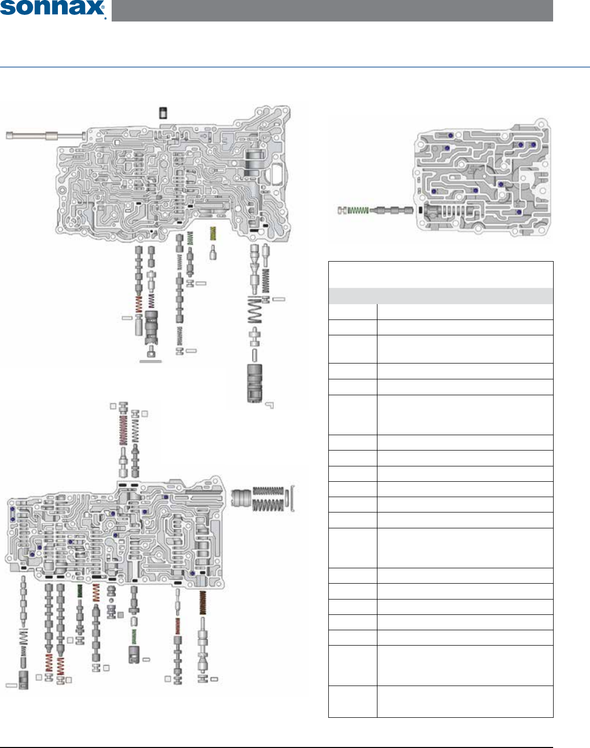
A750 Series Valve Body Descriptions
I.D. No. Description
101 Manual Valve
102 SLT Damper
103 Primary Regulator Valve (inboard)
Boost Assembly (outboard)
104 Clutch Control Valve
105 Clutch Apply Control Valve
106
Accumulator Control Valve (inboard)
Accumulator Control Plunger Valve
& Sleeve (outboard)
107 Sequence Valve
201 Solenoid Modulator Valve
202 Clutch Lock Valve
203 B1 Accumulator Piston
204 Secondary Regulator Valve
205 Lockup Relay Valve
206
Lockup Control Valve (inboard)
Lockup Control Plunger Valve
& Sleeve (outboard)
207 C3 Check Valve
208 3-4 Shift Valve
209 Brake Control Valve
210 2-3 Shift Valve
211 1-2 Shift Valve
212
B1 Apply Control Valve (inboard)
B1 Apply Control Plunger Valve &
Sleeve (outboard)
301 Coast Brake Relay Valve
Note: May not have a valve in this location if the upper
cover or upper valve body #2 casting number is 89010.
OE Exploded View
A750 Valve Body
Filter
101
103
102
107
106 105
104
Check
Valve
Lower
Valve Body
201 202
203
212 211 210
209
208
207
206
205 204
Upper
Valve Body
301
Upper
Valve Body
No. 2
Toyota/Lexus A750E/F, A760E/F/H, A761E, A960E/F, AB60E/F ZIP KIT® Installation & Testing Booklet
©2017 Sonnax Industries, Inc. A750E-A761E-ZIP-Booklet_C 08-03-17
800-843-2600 • 802-463-9722 • F: 802-463-4059 • www.sonnax.com Page 7
TIME TESTED • INDUSTRY TRUSTED
A760, A960 & AB60 Series Valve Body
A760, A960 & AB60 Series
Valve Body Descriptions
I.D. No. Description
101 Brake Control Valve
102
Accumulator Control Valve (inboard)
Accumulator Control Plunger Valve
& Sleeve (outboard)
103 SL1 Relay Valve
104 B1 Apply Relay Valve
105 Solenoid Modulator Valve
201 Manual Valve
202 SLT Damper
203 Primary Regulator Valve (inboard)
Boost Valve Assembly (outboard)
204 4-5 Shift Valve
301 B2 Accumulator Piston
302 Reverse Sequence Valve
303 Clutch Control Valve
304 Clutch Apply Relay Valve
305 B1 Accumulator Piston
306 Secondary Regulator Valve
307 Lockup Relay Valve
308
Lockup Control Valve (inboard)
Lockup Control Plunger Valve
& Sleeve (outboard)
309 C3 Check Valve
310 1-2 Shift Valve
311 B4 Check Valve
312 2-3 Shift Valve
313 3-4 Shift Valve
314 B2 Accumulator Piston
401 C3 Apply Relay Valve
401
Upper
Valve Body
No. 2
Lower
Valve Body
No. 2
105
101
103
102
104
Filter
Check
Valve
Lower
Valve Body
201
202
203
204
301
302
307 306
Upper
Valve Body
304
303
305
308
309
311
310
314
313 312
NOTE: Checkballs are shown in proper location for
A760 series valve bodies. Reference page 8 for proper
checkball location in A960 series valve bodies.
Toyota/Lexus A750E/F, A760E/F/H, A761E, A960E/F, AB60E/F ZIP KIT® Installation & Testing Booklet
08-03-17 A750E-A761E-ZIP-Booklet_C ©2017 Sonnax Industries, Inc.
Page 8 800-843-2600 • 802-463-9722 • F: 802-463-4059 • www.sonnax.com
TIME TESTED • INDUSTRY TRUSTED
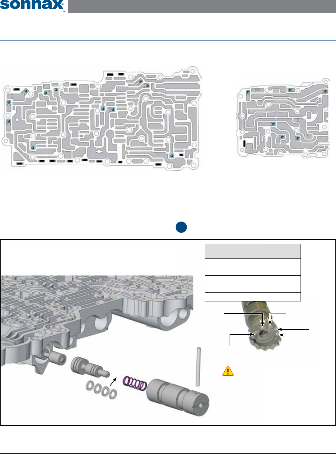
Detailed Instructions for Step from Quick Guide
9
Replace OE Accumulator Control
Plunger Valve & Sleeve Assembly
See chart for number of
Sonnax shims to add.
Figure 8
OE Castellated Plunger Sleeve
Prior to removal, note the position
of the OE retaining pin on the
adjustable notch!
Shallowest
Notch
Deepest
Notch
Middle
Notch
OE Sleeve
Notch Location
Use This Many
Sonnax Shims
Deepest Notch 0
2nd Deepest Notch 1
Middle Notch 2
2nd Shallowest Notch 3
Shallowest Step 4
2nd
Shallowest
Notch
2nd
Deepest
Notch
Upper
Valve Body
Small Upper
Valve Body
OE Exploded View
A960 Series Valve Body • Proper Check Ball locations
