AW60 41SN ZIP IN
Aw60-41Sn-Zip-In AW60-41SN-ZIP-IN AW60-41SN-ZIP-IN 2770 instructions part uploads sonnax-dev
2015-02-11
: Sonnax Aw60-41Sn-Zip-In AW60-41SN-ZIP-IN 1775 file instruction uploads
Open the PDF directly: View PDF ![]() .
.
Page Count: 10
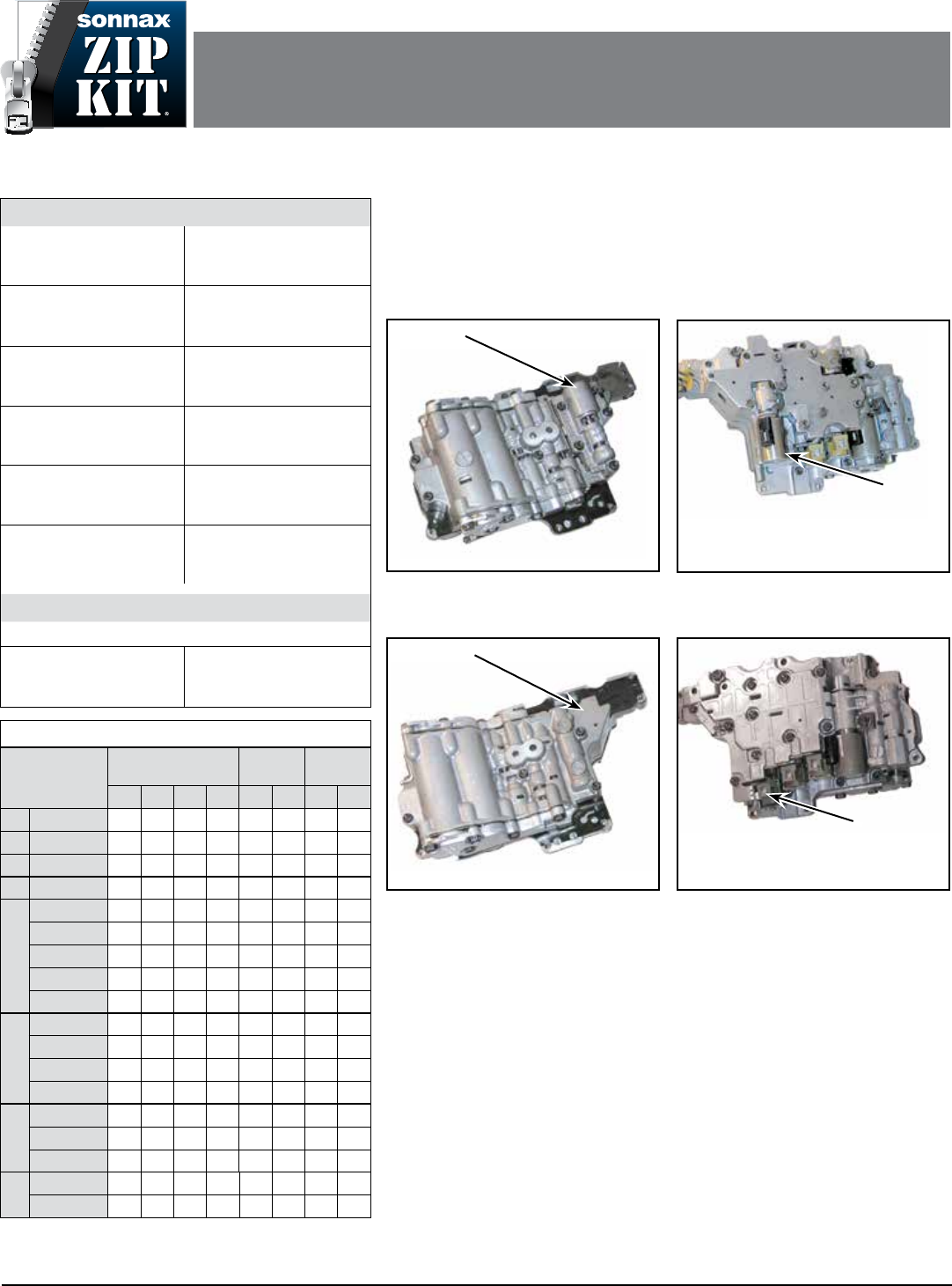
PART NUMBER AW60-41SN-ZIP QUICK GUIDE
©2015 Sonnax Industries, Inc. AW60-41SN-ZIP-Guide 02-11-15
800-843-2600 • 802-463-9722 • F: 802-463-4059 • www.sonnax.com Page 1
AISIN AW 60-41SN (AF-17)
ZIP KIT
Parts are labeled here in order of installation. See other side of sheet for details on Zip Kit contents.
installation Diagram
In addition to general rebuilding tips and technical information, the technical booklet included in this kit contains vacuum testing
and additional repair options for higher mileage units or for repairing specic complaints which are beyond the scope of this kit.
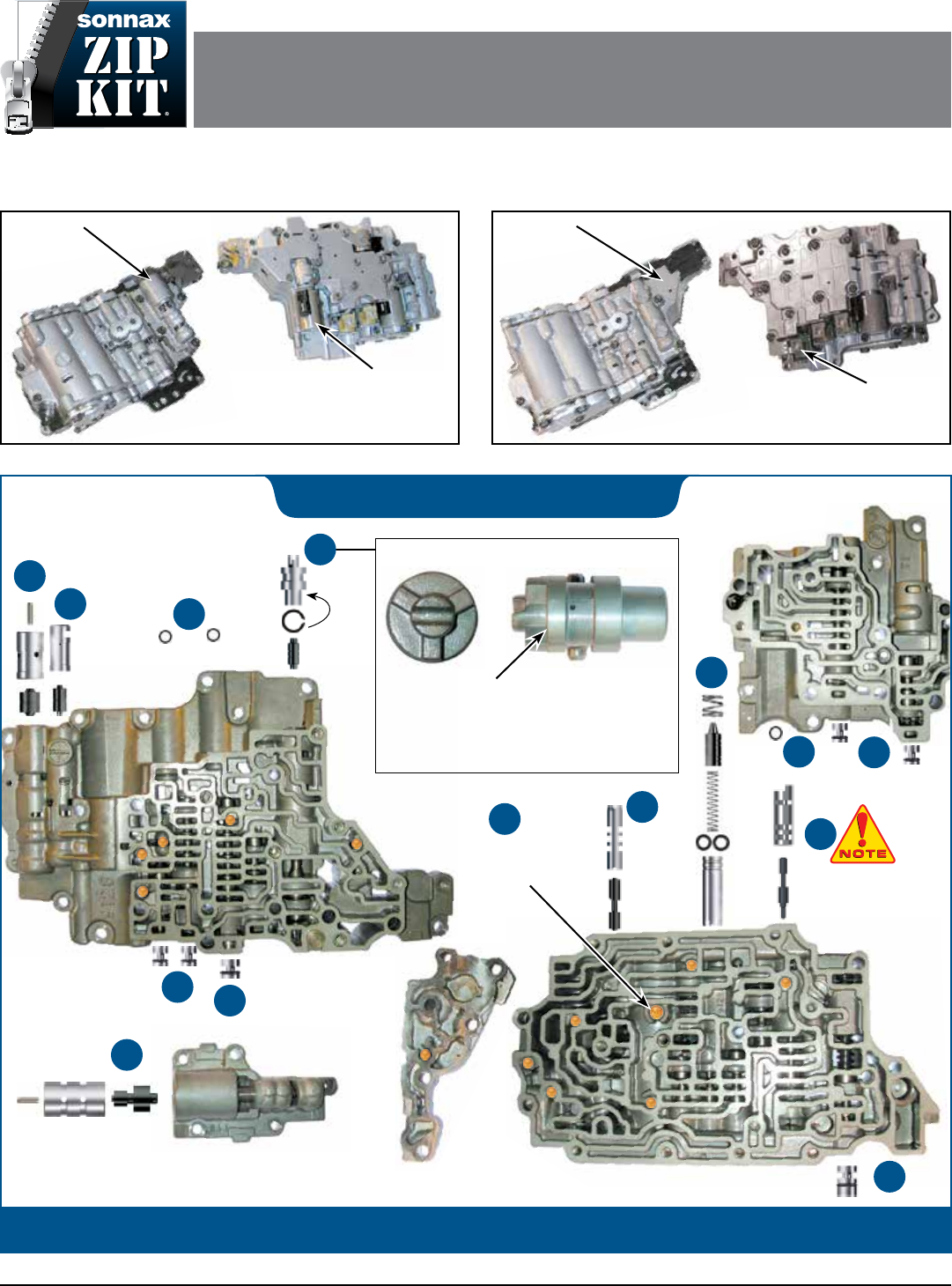
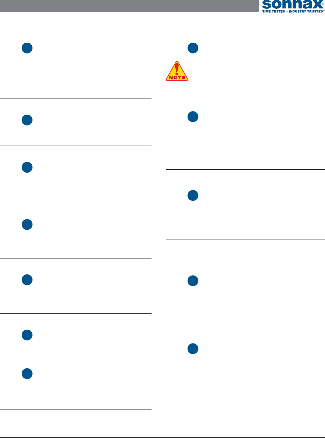
60-40LE (AF-13) Valve Body
No
Number 2
Rear Control
Body
Has a
Short TCC
Solenoid
Valve Body Identication NOTE: This Zip Kit AW60-41SN-ZIP is designed for 60-41SN (AF-17) applications only.
A separate Zip Kit AW60-40LE-ZIP is available for 60-40LE (AF-13) applications.
4
Front Control
Valve Body
10
11
9
Rear Control Valve Body
7
No. 2 Rear Control
Valve Body
2
3
4
5
6
Middle Control
Valve Body
12
Checkballs
12 Small
1 Large
6
Shim
Location
Check which step the retainer location sleeve is on,
to determine how many shims (if any) are required for
Sonnax replacement assembly.
OE Assembly Shown
Lowest of three OE
sleeve steps.
1
Has a
Number 2
Rear Control
Body
60-41SN (AF-17) Valve Body
Has a
Long TCC
Solenoid
8
NOTE: Clocking
is important; see
details on next page.
Aisin AW 60-41SN ZIP KIT Quick Guide
©2015 Sonnax Industries, Inc. AW60-41SN-ZIP-Guide 02-11-15
800-843-2600 • 802-463-9722 • F: 802-463-4059 • www.sonnax.com Page 2
Step Replace OE Reverse Boost
Assembly
Observe the step location of the retainer on OE sleeve prior to removal.
If set at the lowest step, do not use the Sonnax shims. If set at middle
step, use one Sonnax shim. If set at the highest step, use two Sonnax
shims. Shims should be placed on inboard sleeve diameter.
Packaging Pocket 1
• Valve • Sleeve • Shims (3) 1 extra
Step Replace OE Accumulator
Control Plunger Valve Assembly
Packaging Pocket 2
• Valve • Sleeve
Step Replace OE B1 Modulator
Plunger Valve Assembly
Discard OE retainer and use replacement pin to retain lineup.
Packaging Pocket 3
• Valve • Sleeve • Retaining Pin
Step Replace OE End Plugs
Place O-rings in large groove, lubricate with Sonnax Slippery Stick
O-LUBE and roll to size on bench. Install end plugs with O-ring outboard.
Packaging Pocket 4
• End Plugs, Medium (4) • O-Rings, Medium (6) 2 extra
Step Replace OE End Plugs
Place O-rings in large groove, lubricate with Sonnax Slippery Stick
O-LUBE and roll to size on bench. Install end plugs with O-ring outboard.
Packaging Pocket 5
• End Plug, Large • O-Rings, Large (2) 1 extra
Step Replace OE Solenoid O-Rings
Packaging Pocket 6
• O-Rings, Small (4) 1 extra
Step Replace OE TCC Control
Plunger Valve Assembly
Discard OE retainer and use replacement pin to retain sleeve.
Packaging Pocket 7
• Valve • Sleeve • Retaining Pin
1
2
3
4
5
6
7
Step Replace OE Lockup Relay
Plunger Valve Assembly
NOTE: Clocking is important; when properly installed, sleeve
ports face upward and endface protrusion to the left of the plate.
Packaging Pocket 8
• Valve • Sleeve
Step Replace OE C1 Damper Piston
Assembly
Place O-rings in the two sleeve grooves, lubricate with Sonnax Slippery Stick
O-LUBE and roll to size on bench. Push into bore, O-ring end outboard.
Place long, narrow spring into valve pocket. Push into installed sleeve,
spring end rst. Larger diameter spring functions as sleeve retainer.
Packaging Pocket 9
• Valve • Sleeve • Springs (2) • O-Rings, Large (3) 1 extra
Step Rework OE C1 Control Assembly
Install Sonnax C1 control valve assembly into existing OE C1 control sleeve.
Remove and discard OE valve. Install replacement assembly into OE sleeve
tapered end (four notches) rst. Ensure Sonnax valve has oriced spool at
the blind-bottom end of the OE sleeve.
Packaging Pocket 10
• Valve • Sleeve
NOTE: This sleeve is designed to be a slight/hand press t-to-minimal slip
t into the OE sleeve.
Step Replace OE Secondary
Regulator Valve End Plug
Place O-rings in large groove, lubricate with Sonnax Slippery Stick O-LUBE
and roll to size on bench. Install end plugs with O-ring outboard.
Packaging Pocket 11
• End Plug, Large • O-Rings, Large (2) 1 extra
Step Replace OE Checkballs
Packaging Pocket 12
• Checkballs, Small .218" dia. (12) • Checkball, Large .250" dia.
8
9
10
11
12
Zip Kit Contents & Installation Steps
NOTE: This Zip Kit AW60-41SN-ZIP is designed for 60-41SN (AF-17) applications only.
A separate Zip Kit AW60-40LE-ZIP is available for 60-40LE (AF-13) applications.
Valve Body Identication
60-41SN (AF-17) Valve Body: Use this kit.
60-40LE (AF-13) Valve Body: Use AW60-40LE-ZIP kit.
Component Apply Chart
Position Clutch Brake 1-Way
Clutch
C0 C1 C2 C3 B1 B2 F0 F1
PX
R < = 7 mph X X X
R > 7 mph X X
NX
D
1X X X X
2X X X X
N Cont. X X X X
3X X X X
4X X X
3
1X X X X
2X X X X
3X X X X
4X X X
2
1X X X X
2X X X X
(3rd) X X X X
11X X X X X
(2nd) X X X X
Torque Specifications
Manual Shaft Detent
Spring Bolt
89 in-lb
Manual Shift Shaft Detent
Lever Bolts
89 in-lb
Manual Shift Shaft
Retaining Nut
61 in-lb
Park/Neutral Position
Switch Bolt
18 ft-lb
Transmission Speed
Sendor Bolt
48 in-lb
Torque Converter
Housing Bolts
22 ft-lb
Transmission Case
Cover Bolts
18 ft-lb
Transmission Fluid
Bafe Bolts
48 in-lb
Transmission Fluid
Drain Plug
29 ft-lb
Transmission Fluid Pump
Cover Bolt
89 in-lb
Transmission Fluid
Pump-to-Case Bolt
18 ft-lb
Valve-Body-to-Case
Bolts
18 ft-lb
Fluid Chart
Recommended Capacities: Toyota / GM T-IV ATF
Approximate Capacity,
Complete Overhaul
7.6 qt (7.2L)
Approximate Capacity,
Drain and Fill
4.2 qt (4.0L)
Has a
Number 2
Rear Control
Body
60-41SN (AF-17) Valve Body 60-41SN (AF-17) Valve Body
Has a
Long TCC
Solenoid
60-40LE (AF-13) Valve Body
Has a
Short TCC
Solenoid
60-40LE (AF-13) Valve Body
No
Number 2
Rear Control
Body
AISIN AW 60-41SN (AF-17)
ZIP KIT
PART NUMBER AW60-41SN-ZIP INSTALLATION & TESTING BOOKLET
©2015 Sonnax Industries, Inc. AW60-41SN-ZIP-Booklet 02-11-15
800-843-2600 • 802-463-9722 • F: 802-463-4059 • www.sonnax.com Page 1
Aisin AW 60-41SN ZIP KIT Installation & Testing Booklet
02-11-15 AW60-41SN-ZIP-Booklet ©2015 Sonnax Industries, Inc.
Page 2 800-843-2600 • 802-463-9722 • F: 802-463-4059 • www.sonnax.com
TIME TESTED • INDUSTRY TRUSTED
Solenoid Apply Chart
Position
Solenoid
S1 S2 SN SLU
PX
R< = 7 mph X
R> 7 mph X
NX
D
1X
2X X
N Cont. XXX
3X X
4X
3
1X
2X X
3X X
4X
2
1X
2X X
(3rd) X X
1
1X
(2nd) X X
Electronic Cautions
Performance Modes
e transmission control module (TCM) programming allows the driver to select
among various modes for enhanced performance based upon driving conditions.
e TCM itself has the capability to change modes automatically when specic
conditions are met. ese modes will alter shift feel, and could be confused with
shift problems by the driver if they are unaware of the TCM programming.
• Economy Mode/Power Mode The transmission is programmed to start
and operate in Economy Mode. This shift strategy sets the shift points to
occur at a lower speed than Power Mode to maximize fuel economy. The TCM
will automatically switch to Power Mode when the driver accelerates more
aggressively (higher engine load), or at higher speed, maximizing performance.
• Winter Mode is activated by the driver by a switch on the shifter. This mode
starts the vehicle in 3rd gear to reduce tire slip on icy/slippery roads. Once the
vehicle is moving, the TCM will automatically shift to the appropriate gear.
Shifting into manual 1st or 2nd will cancel Winter Mode.
• Neutral Control is automatically activated by the TCM if the vehicle is in
Drive and comes to a stop for longer than 2 seconds with the brakes applied.
This condition allows the C1 (forward clutch) to be disengaged, placing the
vehicle in Neutral, for improved fuel economy. When the brake is released,
the C1 clutch is automatically applied and the vehicle will take off in 1st gear.
• Hill Hold The TCM monitors vehicle speed to determine if the driver is
coming to a stop on a hill. If so, the TCM will automatically apply the B1 (2/4
brake) to prevent vehicle rolling. Upon takeoff, the B1 brake is released, and
the vehicle moves forward in 1st gear. The TCM will disable Neutral Control
if Hill Hold is activated.
Solenoids
is 60-41SN unit uses ve solenoids (Figure 1).
• The S1 solenoid is an on/off style, operated by
the TCM to control the 2-3 shift.
• The S2 solenoid is an on/off style, operated by
the TCM to control the 1-2 and 3-4 shifts.
• The SN solenoid is an on/off style, operated by
the TCM to operate Neutral Control.
• The SLU linear solenoid is pulse width
modulated by the TCM to operate the converter
clutch.
• The SLT linear solenoid is modulated by the
TCM to regulate line pressure.
Figure 1
SLT Solenoid
3.3–3.7 ohm
SN Solenoid
12–16 ohm
SLU Solenoid
5.0–5.6 ohm
S2 Solenoid
11–15 ohm
S1 Solenoid
11–15 ohm
Test all ve solenoids at 20˚C/68˚F.
Aisin AW 60-41SN ZIP KIT Installation & Testing Booklet
©2015 Sonnax Industries, Inc. AW60-41SN-ZIP-Booklet 02-11-15
800-843-2600 • 802-463-9722 • F: 802-463-4059 • www.sonnax.com Page 3
TIME TESTED • INDUSTRY TRUSTED
Zip Kit Instructions
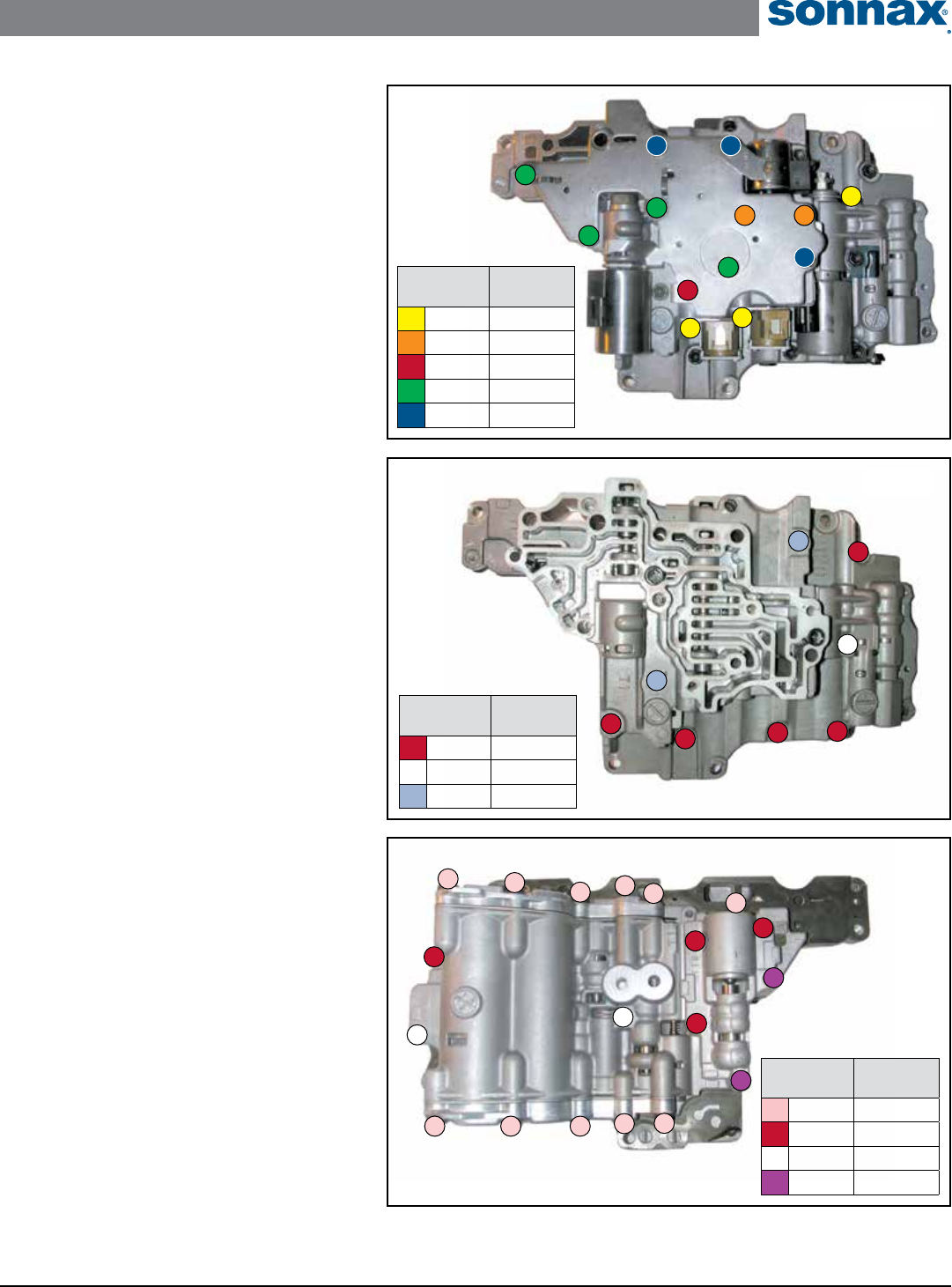
1. Valve Body Disassembly
NOTE: See color charts for bolt lengths.
a. Remove the 13 bolts (Figure 2).
b. Remove the ve solenoids (Figure 2).
c. Remove the eight bolts (Figure 3).
d. Remove the central (non-pink-coded) bolts
(Figure 4). e two rear valve body covers can be
removed to access bore components by removing
the 11 cover bolts (pink-coded).
2. Installation
Install Zip Kit parts as shown on diagram of
separate quick guide sheet included in this Zip Kit.
3. Valve Body Assembly
a. Loosely install the central (non-pink-coded) bolts
(Figure 4), then torque to 59 in-lb. e 11 cover
bolts (pink-coded) should be torqued to 89 in-lb.
b. Loosely install the eight bolts (Figure 3), then
torque to 59 in-lb.
c. Reinstall the ve solenoids (Figure 2).
d. Loosely install the 13 bolts (Figure 2), then
torque to 59 in-lb.
Bolt Color
Code
Bolt
Length
Yellow 10mm
Orange 12mm
Red 16mm
Green 40mm
Blue 75mm
Figure 2
Bolt installation torque specications are 59 in-lb.
Bolt Color
Code
Bolt
Length
Red 16mm
White 38mm
Lt Blue 54mm
Figure 3
Bolt installation torque specications are 59 in-lb.
Bolt Color
Code
Bolt
Length
Pink 12mm
Red 16mm
White 38mm
Purple 50mm
Figure 4
Bolt installation torque specications are 59 in-lb for all
except for Pink code, 12mm bolts, which are 89 in-lb.
Aisin AW 60-41SN ZIP KIT Installation & Testing Booklet
02-11-15 AW60-41SN-ZIP-Booklet ©2015 Sonnax Industries, Inc.
Page 4 800-843-2600 • 802-463-9722 • F: 802-463-4059 • www.sonnax.com
TIME TESTED • INDUSTRY TRUSTED
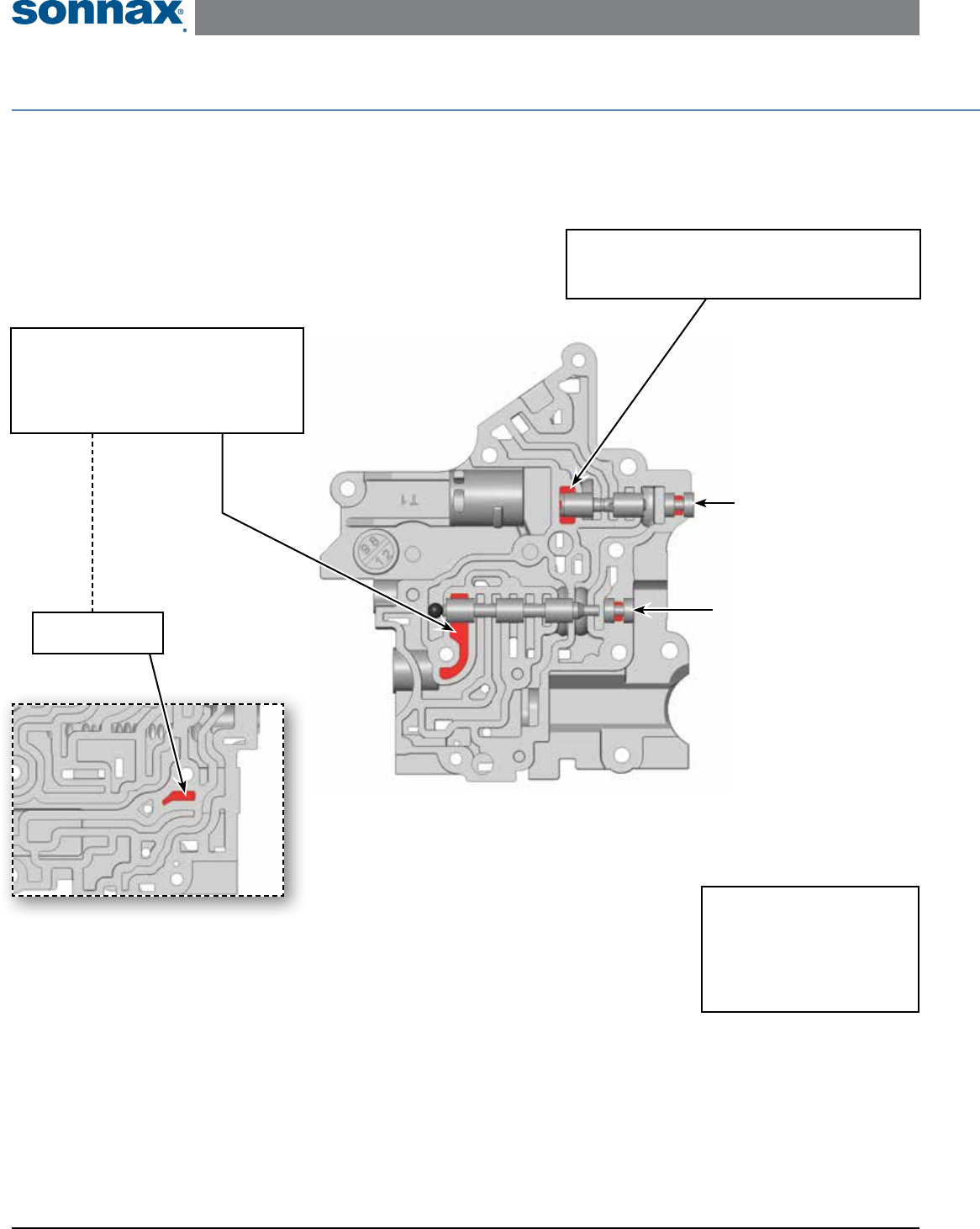
Critical Wear Areas & Vacuum Test Locations
NOTE: OE valves are shown in rest position and should be tested in rest position unless otherwise indicated. Test locations are pointed to with an arrow.
Springs are not shown for visual clarity. Low vacuum reading indicates wear.
Front Control Valve Body - Top Side (Bottom Side Inset) Shown Here
Neutral Relay Valve
• Delayed engagement
• Loss of neutral control feature
NOTE: Prop valve in outboard position with checkball
and seal port on opposite side of casting.
Seal for neutral relay
valve vacuum test.
Solenoid B-1 Modulator Valve No. 2
Shift complaints in 2nd & 4th
NOTE: Invert valve (as shown) to test.
Front Control Valve Body
Bottom Side
Front Control Valve Body
Top Side
End Plugs
• Burnt clutches/brakes
• Various shift complaints
Replace with Sonnax Part No.
19741-15K*
NOTE: Several Locations =
* Part numbers with an asterisk (*)
are included in this Zip Kit.
Aisin AW 60-41SN ZIP KIT Installation & Testing Booklet
©2015 Sonnax Industries, Inc. AW60-41SN-ZIP-Booklet 02-11-15
800-843-2600 • 802-463-9722 • F: 802-463-4059 • www.sonnax.com Page 5
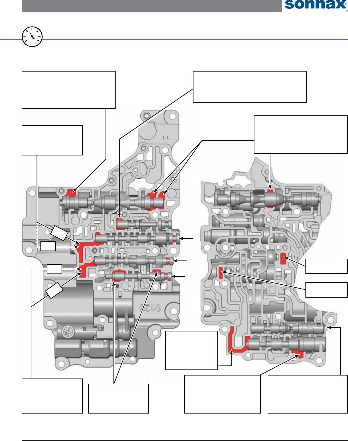
TIME TESTED • INDUSTRY TRUSTED
Middle Control Valve Body - Top & Bottom Sides Shown Here
20
25
15
0
10
5
30
VACUUM
TEST
B1 Modulator
Plunger Valve
Shift complaints in 2nd & 4th
Replace with Sonnax Part No.
19741-03K*
1-2 Shift Valve
1-2 Shift complaints
NOTE: Seal port on opposite
side of casting.
Reverse Boost Assembly
• Low reverse pressure
• Delayed reverse
Replace with Sonnax Part No.
19741-07K*
Lockup Control Solenoid Valve
• Converter slip/shudder/codes
• No converter apply
NOTE: Test port by using 3-4 shift valve in bore instead.
Pressure Regulator Valve
• Low/High line pressure
• Soft/harsh shifts
• Converter complaints
• Loss of lube
Seal for 2-3 shift
valve vacuum test.
Seal for 1-2 shift
valve vacuum test.
Test
Seal
Seal
Test
2-3 Shift Valve
2-3 Shift complaints
NOTE: Seal solenoid port as
well as port on opposite side
of casting.
3-4 Shift Valve
3-4 Shift complaints
NOTE: Seal solenoid port
when testing.
Middle Control Valve Body
Top Side
Middle Control Valve Body
Bottom Side
Solenoid B-1
Modulator
Valve No. 1
Shift complaints in
2nd & 4th
Accumulator Control
Plunger Valve
Shift complaints
Replace with Sonnax Part No.
19741-05K*
Aisin AW 60-41SN ZIP KIT Installation & Testing Booklet
02-11-15 AW60-41SN-ZIP-Booklet ©2015 Sonnax Industries, Inc.
Page 6 800-843-2600 • 802-463-9722 • F: 802-463-4059 • www.sonnax.com
TIME TESTED • INDUSTRY TRUSTED
Critical Wear Areas & Vacuum Test Locations
NOTE: OE valves are shown in rest position and should be tested in rest position unless otherwise indicated. Test locations are pointed
to with an arrow. Springs are not shown for visual clarity. Low vacuum reading indicates wear.
Rear Control Valve Body - Top Side (Bottom Side Inset) Shown Here
20
25
15
0
10
5
30
VACUUM
TEST
No. 2 Rear Control Valve Body
Lockup Relay Control
Valve
Lockup complaints/codes
NOTE: Seal port on opposite side of
casting when testing.
Secondary Regulator Valve
• TCC complaints
• Loss of lube
NOTE: Seal two ports on opposite side of casting when testing two middle ports.
B-1 Modulator Control
Valve
• Shift complaints in 2nd & 4th
• Burned B1 brake
Low Modulator Valve
Delayed forward in Manual 1
NOTE: Test both ports at the same time.
Solenoid Modulator Valve
Shift complaints
NOTE: Test with B-1 modulator valve
in bore instead.
C-1 Damper Piston
• Burned C1 clutch
• Delayed forward
Replace with Sonnax Part No.
19741-17K*
2-3 Timing Valve
& C2 Accumulator
• 2-3 Shift complaints
NOTE: Test both ports at the same time.
C-1 Control
Valve Assembly
• Burned C1 clutch
• Delayed forward
C2 & B1 Accumulators
• Burned C2 clutch
• Bang/Delayed reverse
• Burned B1 brake
• Shift complaints in 2nd & 4th
Lockup Control Valve
• Loss of lockup
• Converter slips/shudder/codes
NOTE: Test with valve blocked inboard
(as shown).
Lockup Control Plunger
Valve Assembly
• Loss of lockup
• Converter slips/shudder/codes
Replace with Sonnax Part No.
19741-01K*
Rear Control Valve Body
Bottom Side
Rear Control Valve Body
Top Side
* Part numbers with an asterisk (*)
are included in this Zip Kit.
C-3 Modulator Valve
• Burned C3 clutch
• Slips in 1st, 2nd & 3rd
NOTE: Test with 2-3 gear timing valve in
bore instead.
Lockup Relay Plunger Valve
• TCC apply & release concerns
• Inadequate lubrication • Overheat
Replace with Sonnax Part No.
19741-09K*
Aisin AW 60-41SN ZIP KIT Installation & Testing Booklet
©2015 Sonnax Industries, Inc. AW60-41SN-ZIP-Booklet 02-11-15
800-843-2600 • 802-463-9722 • F: 802-463-4059 • www.sonnax.com Page 7
TIME TESTED • INDUSTRY TRUSTED
101
102
Front Control
Valve Body
Filter
Filter
208
Middle Control Valve Body
(Front Side)
207
206
201
202
203
204
205
Front Control Valve Body Descriptions
I.D. No. Description
101 Solenoid B-1 Modulator Valve
No. 2
102 Neutral Relay Valve
OE Exploded View
Front & Middle Control Valve Bodies Shown Here
Middle Control Valve Body Descriptions
I.D. No. Description
201 Pressure Relief Valve
202 Lockup Control Solenoid Valve
203 3-4 Shift Valve
204 2-3 Shift Valve
205 1-2 Shift Valve
206 Solenoid B-1 Modulator
Valve No.1
207 Accumulator Regulator Valve and
Plunger Valve Assembly
208 Primary Regulator Valve
& Reverse Boost Assembly
209 Pressure Relief Valve
Middle Control
Valve Body
(Bottom Side)
209
Aisin AW 60-41SN ZIP KIT Installation & Testing Booklet
02-11-15 AW60-41SN-ZIP-Booklet ©2015 Sonnax Industries, Inc.
Page 8 800-843-2600 • 802-463-9722 • F: 802-463-4059 • www.sonnax.com
TIME TESTED • INDUSTRY TRUSTED
316
315
314
313
312
311
310
309
308
307
306
305
303
304
302
301
Rear Control Valve Body Descriptions
I.D No. Description
301 Secondary Regulator Valve
302 Check Valve
303 B-1 Modulator Control Valve
304 Low Modulator Valve
305 Solenoid Modulator Valve
306 C-2 Accumulator
307 B-1 Accumulator
308 Manual Valve
309 C-1 Control Valve Assembly
310 C-0 Accumulator
311 2-3 Timing Valve
312 C-1 Damper Piston
313 C-3 Modulator Valve
314 Lockup Relay Control Valve
& Plunger Assembly
315 Check Valve
316 Check Valve
No. 2 Rear Control Valve Body
Descriptions
I.D. No. Description
401 TCC Control Valve
& Plunger Valve Assembly
Rear Control
Valve Body
OE Exploded View
Rear & No. 2 Rear Control Valve Bodies Shown Here
No. 2 Rear Control
Valve Body
401
Filter
No. 2 Rear Control
Valve Body
