F025 Tech Install
2018-08-16
: Sonnax F025-Techinstall F025-TechInstall 4045 instructions part uploads
Open the PDF directly: View PDF ![]() .
.
Page Count: 2
FNR5, FN5A-EL
Remanufactured
Valve Body
Part No.
F025
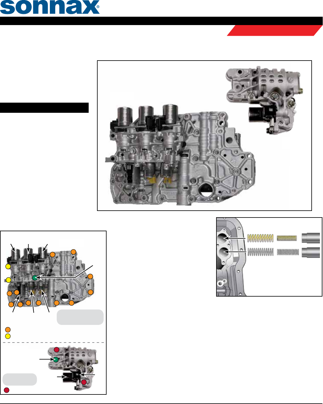
Figure 1
NOTE: 1-2 Accumulator springs
have
a larger coil diameter and are generally
shorter than the N-D accumulator
springs. Springs go in the case rst
then are followed by the piston.
1-2 Accumulator
N-D Accumulator
Valve Body Installation Tips
1. Verify Case
a. Verify two rubber seals are installed
on the top of the valve body. Verify
accumulator springs and pistons are
installed into case correctly (Figure
1). Install valve body onto transmis-
sion case while indexing the manual
valve link into the manual linkage.
b. Install the 13 valve body-to-case
bolts in the noted locations
(Figure 2).
Torque them in the sequence shown, this can help prevent valve bind.
c. See ground strap bolt location (Figure 2) and refer to chart (Figure 3) for connector
color and wire color identication as the internal wire harness connectors can be incor-
rectly installed.
d. Verify the ve seals are installed in the mating surface for the secondary valve body.
Torque the 3 bolts (Figure 2).
NOTE: The green circle is the location for the ground strap from the wiring harness.
2. Fluid Fill and Road Test
a. Fill the transmission to factory spec with OE compatible ATF.
b. Let engine run to help warm transmission uid to 185°.
FNR5 Main
Valve Body
FNR5
Secondary
Valve Body
Figure 2
SSA
PWM
SSB
PWM
SSD
PCA
PWM
SSE
4
3
2
1
Ground
Strap Bolt
Location
5
6
7
8
9
10
11 12
= 40mm long valve body-to-case bolts
Torque all bolts to
80 in-lb in the sequence
shown; starting with 1.
= 71mm long valve body-to-case bolts
SSC
PWM
14
13
Secondary
Valve Body
Main
Valve Body
Ground
Strap Bolt
Location
= Bolts
Torque all bolts
to 80 in-lb
.
SSF
PCB
PWM
©2018 Sonnax Transmission Company, Inc. • A Marmon / Berkshire Hathaway Company F025_TechInstall 06-27-18
866-243-8829 • 856-848-0908 • F: 856-848-1080 • www.sonnax.com Page 1
REMANUFACTURED VALVE BODIES
Tech & Install Tips
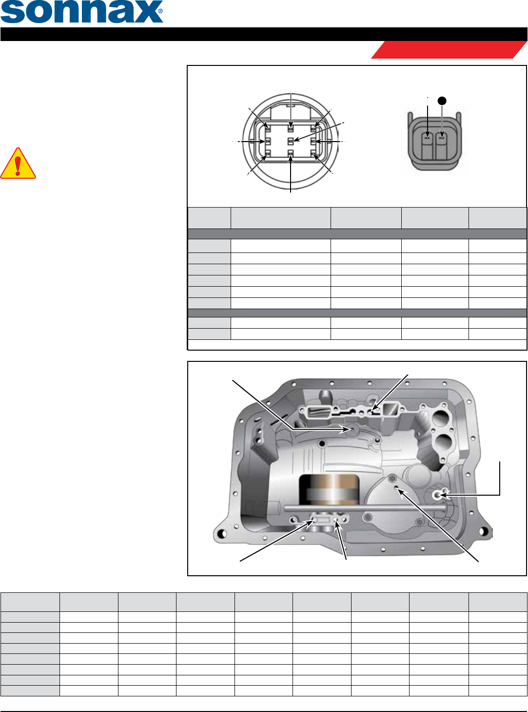
Solenoid Resistance Chart & Wire Harness Information
Transaxle Main
Case Connector
Terminals Solenoid Ohms Resistance
at 20 C (70 F)
Harness
Connector Color
Common Wire
Color(s)
Main ValVe Body
6 & Gnd. Shift Solenoid "D" (PWM) 10.9 – 26.2 Clear White
8 & Gnd. Shift Solenoid "E" (PWM) 10.9 – 26.2 Black Red
3 & Gnd. Shift Solenoid "A" (On-Off) 1.0 – 4.2 White Blue/Green
9 & Gnd. Shift Solenoid "B" (On-Off) 1.0 – 4.2 Blue Blue/Brown
1 & Gnd. Shift Solenoid "C" (PWM) 1.0 – 4.2 Green Black/Green
2 & 7 PC A Solenoid (PWM) 2.4 – 7.3 Black Orange/Blue
Secondary ValVe Body
10 & Gnd. Shift Solenoid "F" (On-Off) 10.9 – 26.2 Black Black
11 & Gnd. PC B Solenoid (PWM) 1.0 – 4.2 White Blue/Green
NOTE: When ohm testing solenoids, ground meter to valve body or case.
FNR5 Application Chart
Gear Range Forward
Clutch 2-4 Brake 3-4 Clutch Reverse
Clutch
Low/Rev
Clutch
Low One Way
Clutch
Direct Clutch
5th
Reduction
Brake & OWC
Park ON
Reverse ON ON ON
Neutral ON
D-1st Gear ON ON ON
D-2nd Gear ON ON ON
D-3rd Gear ON ON ON
D-4th Gear ON ON ON
D-5th Gear ON ON ON
Figure 5
Figure 3
Figure 4
Low & Reverse
Clutch
Servo
Release
Servo ApplyDirect ClutchReverse Clutch
Forward Clutch
2. Fluid Fill & Road Test (continued)
c.
Install capable scan tool to reset transmission
adaptives by resetting "Keep Alive Memory".
d.
Road test vehicle performing 10-15 upshift
and downshift cycles thru all ve speeds.
NOTE:
Downshift clunks can be common during
the relearn. This condition will typically resolve
itself within the 10-15 shift cycles.
3. Bonus Diagnostic Tech
a. is Sonnax remanufactured valve body
has been thru a rigorous inspection and
rebuild process, and then put thru a
comprehensive functional hydraulic and
electronic test to ensure it meets OE
performance and quality.
b. It is designed to eliminate many pressure,
shift, and converter related complaints,
but will not correct complaints that stem
from other areas of the transmission.
c. Following are common areas of failure
or root causes for symptoms that could
be attributed to valve body issues that
should also be examined or addressed
during your transmission build. In addi-
tion (Figures 4 & 5) for air test locations
to verify internal integrity, and a compo-
nent application chart for troubleshoot-
ing driveability issues.
4. Common Failure Areas
a. Forward engagement problems and 4-3
ares and torque converter slip codes can
be attributed to worn stator bushings.
Bushings should be checked and replaced.
b. A 2-3 are can be attributed to wear in
the case between the servo pin and the
bore. In addition the Direct clutch and
the sealing ring tower in the rear of the
case can cause the same issue.
c. A 1-3 shift can be caused by installing
the solenoid connectors backwards
.
11
Transaxele Secondary Case Connector
©2018 Sonnax Transmission Company, Inc. • A Marmon / Berkshire Hathaway Company F025_TechInstall 06-27-18
866-243-8829 • 856-848-0908 • F: 856-848-1080 • www.sonnax.com Page 2
FNR5, FN5A-EL F025
REMANUFACTURED VALVE BODIES
Tech & Install Tips
