HP 4L60E 01 IN
Hp-4L60E-01-In HP-4L60E-01-IN HP-4L60E-01-IN 2928 instructions part uploads sonnax-dev
2016-11-22
: Sonnax Hp-4L60E-01-In HP-4L60E-01-IN 1379 file instruction uploads
Open the PDF directly: View PDF ![]() .
.
Page Count: 5
Instructions
High Performance TRANSMISSION Parts
PERFORMANCE
©2016 Sonnax Industries, Inc. HP-4L60E-01-IN 11-22-16
800-843-2600 • 802-463-9722 • F: 802-463-4059 • www.sonnax.com Page 1
4L60-E, 4L65-E, 4L70-E
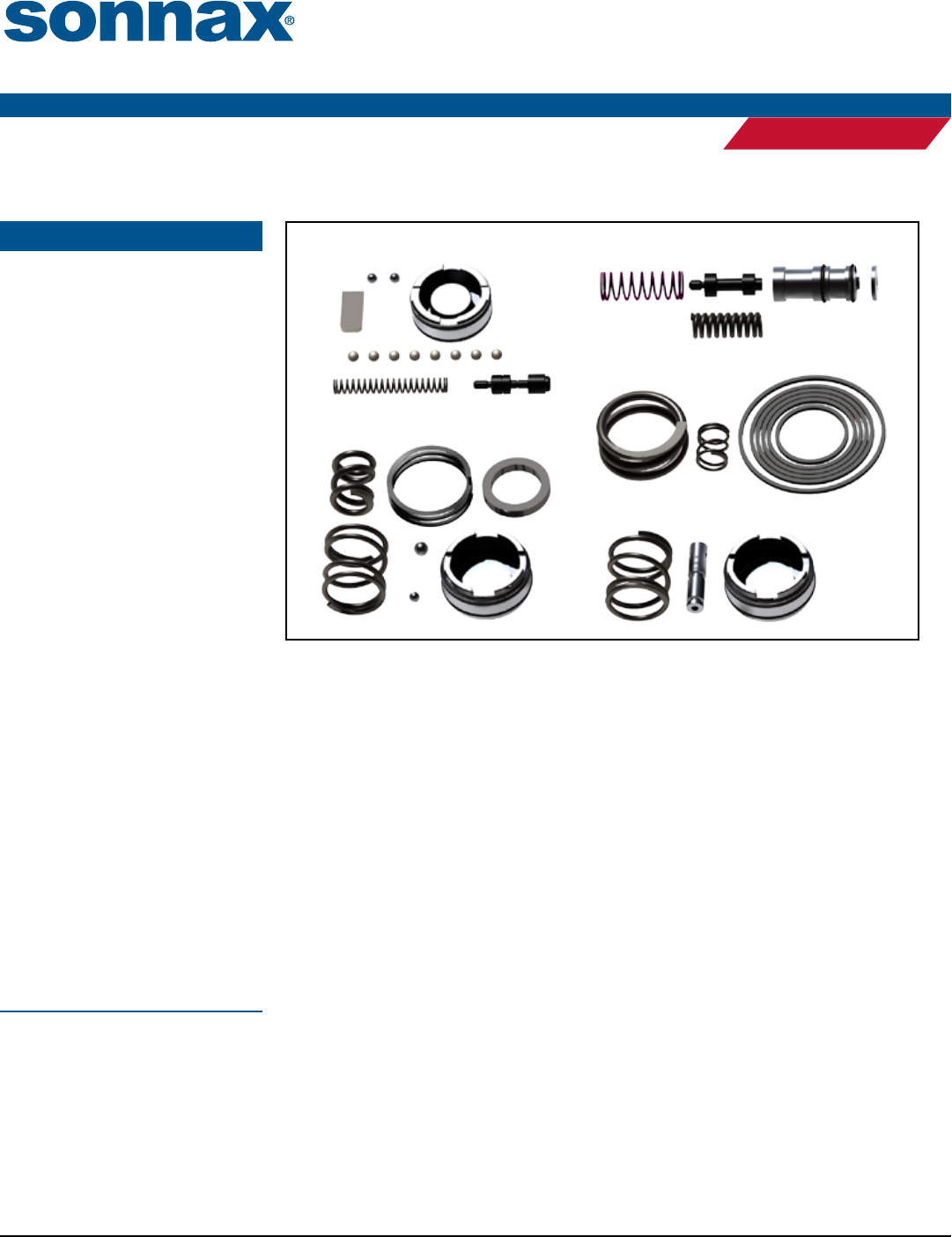
Performance Pack
Part No.
HP-4L60E-01
Fits '94-later units
Pump Parts
• Boost Valve with O-Ring, .490"
• Elevated Pressure Regulator Spring
• High RPM Pump Slide Spring
• Spacer
Servo Parts
• 4th Servo Return Spring
• Servo Cushion Spring
• Servo Piston D-Ring Kit
Case Parts
• 3-4 Accumulator Piston Kit
• 3-4 Accumulator Spring
• Servo Release Check Valve
Valve Body Parts
• Forward Accumulator Kit
• 1-2 Accumulator Valve Shim
• TCC Pressure Limiter:
• TCC Valve
• TCC Spring
• Checkballs (8)
• Separator Plate Plugs Not Shown
• Twist Drills Not Shown
Accumulator Parts
• 1-2 Pinless Accumulator Piston Kit
• 1-2 Accumulator Inner Spring
• 1-2 Accumulator Outer Spring
• 1-2 Accumulator Waved Spring
• Accumulator Housing Spacer
The parts listed here may be protected by
one of these patent numbers: 6,619,323
& 6,899,211.
NOTE: For more radical applications
and even greater levels of performance,
combine the Performance Pack with the
Sonnax 2nd Gear Super Hold Servo Kit
77911-03K and 4th Gear Super Hold Dual
Servo Kits 77911-03K & Kit 77767K.
Accumulator Parts
Valve Body Parts Pump Parts
Servo Parts
Case Parts
Before You Begin
1996-1998 4L60-E applications with two solenoids on front of valve body are programmed
for pulse-width modulated (PWM) torque converter clutch (TCC) control. 1998-later
applications are programmed for “partial slip” of the TCC under light load conditions (EC3).
Both applications have clutch friction material specially suited to partial slip conditions. High
performance converters may be built with on/o friction material that should not be allowed
to slip. For converters built with on/o material, it is necessary to disable the partial slip
function of the transmission by reprogramming the computer or modifying the transmission.
e Sonnax TCC pressure limiter is a calibrated pressure-control spring that allows on/o
converter operation without causing converter pressures to go too high. Other common
modications to the TCC regulator bore in the valve body which block the valve or add a
dierent valve/spring combination cause line pressure to apply the converter clutch at double
normal converter pressures. is leads to extra force on the engine crankshaft thrust bearing
and causes TCC piston exing that – over time – leads to broken rivets and converter failure,
as well as trouble codes.
e TCC pressure limiter modication in this kit is the ONLY available modication that
both eliminates PWM/EC3 operation AND regulates converter pressure to acceptable levels.
If you desire to keep OE PWM/EC3 operation, DO NOT install Sonnax pressure limiter.
Ensure correct PWM/EC3 friction material is used in your converter.
With the pressure limiter spring and Sonnax TCC valve from the Performance Pack or the
Sonnax sleeve kit 77754-04K*, TCC apply pressure will be limited to about 100 psi. With the
pressure limiter spring and Sonnax sleeve kit 77754-03K*, TCC apply pressure will be limited
to about 120 psi.
*Kits sold separately.
©2016 Sonnax Industries, Inc. HP-4L60E-01-IN 11-22-16
800-843-2600 • 802-463-9722 • F: 802-463-4059 • www.sonnax.com Page 2
PERFORMANCE PACK HP-4L60E-01
Instructions
High Performance TRANSMISSION Parts
PERFORMANCE
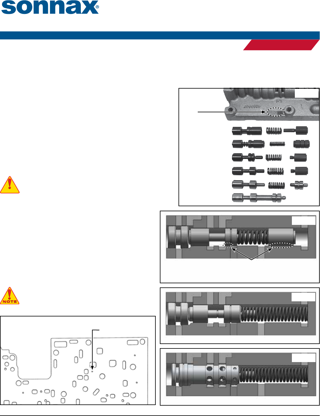
Figure 2
OE TCC Regulator Valve Bore
Inspect for wear. Any significant
wear results in line pressure leakage
to exhaust, regardless of valve type.
Figure 4
Sonnax Regulator Valve and Limiter Spring in OE Bore
Figure 5
Sonnax Regulator Valve Sleeve Kit with Limiter Spring in Reamed Bore
Figure 1
“SERV” stamped
here indicates
a reamed valve
body.
“SERV” Valve Body
‘01-Later
‘97–‘00 EC3
‘96–‘97 PWM
‘95–‘96 PWM
‘93–‘94 non-PWM
Valve Body Parts
1. Determine what style TCC valve is in your valve body by comparing valve lineup (Figure 1).
• For ‘93-‘94 Non-PWM: Original valve can be reused, there is no need to install Sonnax TCC Pressure Limiter unless bore is worn. If bore
is worn, it must be reamed and Sonnax sleeve kit 77754-03K* installed.
• For all ‘95-Later: Follow inspection and installation steps.
•
‘96-Later GM Remanufactured “SERV” with Oversized TCC Regulator:
Reference Sonnax guidelines for tool 77754-SERV. See Figure 1 to
identify a SERV valve body.
2. Inspect TCC regulator valve bore for wear (Figure 2). Vacuum testing
is the preferred and most reliable testing method.
3. If the bore is okay, proceed to Step 2 for pressure limiter installation
instructions. If the bore is excessively worn, it must be reamed and
Sonnax sleeve kit 77754-04K* or 77754-03K* installed.
2. Pressure Limiter Installation
CAUTION: Before installing pressure limiter, see "Before You
Begin" section on page one.
a. Locate the PWM hole in the separator plate. Bore this orice with a
1/16" drill bit, then lightly chamfer both sides of the plate.
Install Sonnax small aluminum plug and peen in place with a
hammer (Figure 3).
b. • For un-reamed OE bore, install Sonnax TCC limiter
spring, then the Sonnax regulator valve included in this kit
and OE end plug (Figure 4).
• For bore reamed to accept Sonnax regulator valve/sleeve kit
77754-04K* or 77754-03K*, install Sonnax TCC limiter
spring, then the regulator valve/sleeve kit 77754-04K* or
77754-03K* and discard the regulator valve included in
this kit (Figure 5).
NOTE: Do NOT install inner isolator valve with the
pressure limiter spring.
*Kits sold separately.
CAUTIONCAUTION
CAUTIONCAUTION
PWM TCC Feed or 2nd
Clutch Oil on Non-PWM Units Plug PWM Hole
Figure 3
©2016 Sonnax Industries, Inc. HP-4L60E-01-IN 11-22-16
800-843-2600 • 802-463-9722 • F: 802-463-4059 • www.sonnax.com Page 3
PERFORMANCE PACK HP-4L60E-01
Instructions
High Performance TRANSMISSION Parts
PERFORMANCE
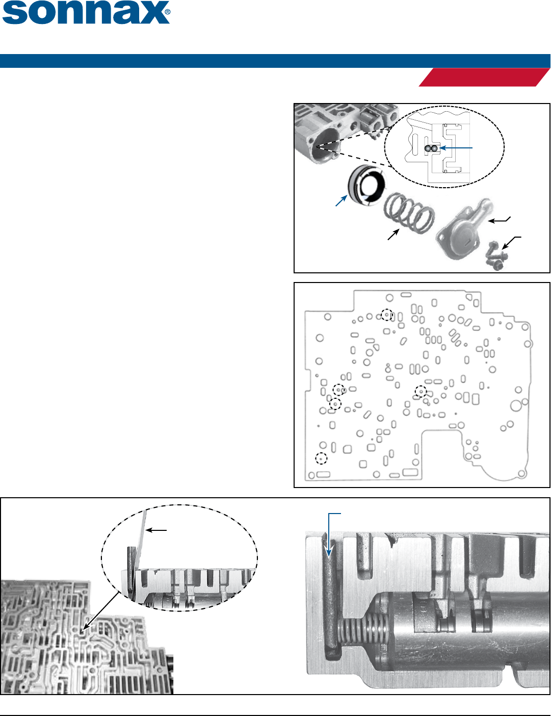
3. Pinless Forward Accumulator Installation
a. Remove OE piston, pin and seal and discard (do not reuse the
OE D-ring seal).
b. Plug the pin bore in bottom of accumulator bore by installing
two .238" dia. Sonnax steel balls (Figure 6). Lightly stake pin bore
after driving balls in.
c. Install Sonnax D-ring seal at domed end of piston. Install
Sonnax PTFE seal at open end of piston.
d. Install Sonnax piston and OE spring. Secure with OE cover
and screws (Figure 6).
4. Separator Plate
a. Drill the plate as indicated to the following specications
(Figure 7):
• Hole “A” (3-2 shift) use drill .093" #42.
• Hole “B” (2nd clutch) use drill .093" #42.
• Hole “C” (3rd clutch) use drill .093" #42.
• Hole “D” (4th clutch) use drill .093" #42.
• Hole “E” (AFL balance oil) use drill .052" #55.
b. Install eight Sonnax plastic checkballs in original locations.
5. 1-2 Accumulator Valve Shim Installation
a. Reuse OE accumulator valve spring.
b. Install shim into sleeve pocket, beveled side down. is can be
done by removing the accumulator valve or by simply insert-
ing the shim between the spring and the end of the bore using a
feeler gauge as an installation tool (Figure 8).
Figure 6
Forward
Accumulator
Kit
Steel
Balls
OE
Spring
OE
Screws
OE
Cover
Figure 7
A
B
D
E
C
Figure 8
Accumulator
Valve Shim
Feeler
Gauge
©2016 Sonnax Industries, Inc. HP-4L60E-01-IN 11-22-16
800-843-2600 • 802-463-9722 • F: 802-463-4059 • www.sonnax.com Page 4
PERFORMANCE PACK HP-4L60E-01
Instructions
High Performance TRANSMISSION Parts
PERFORMANCE
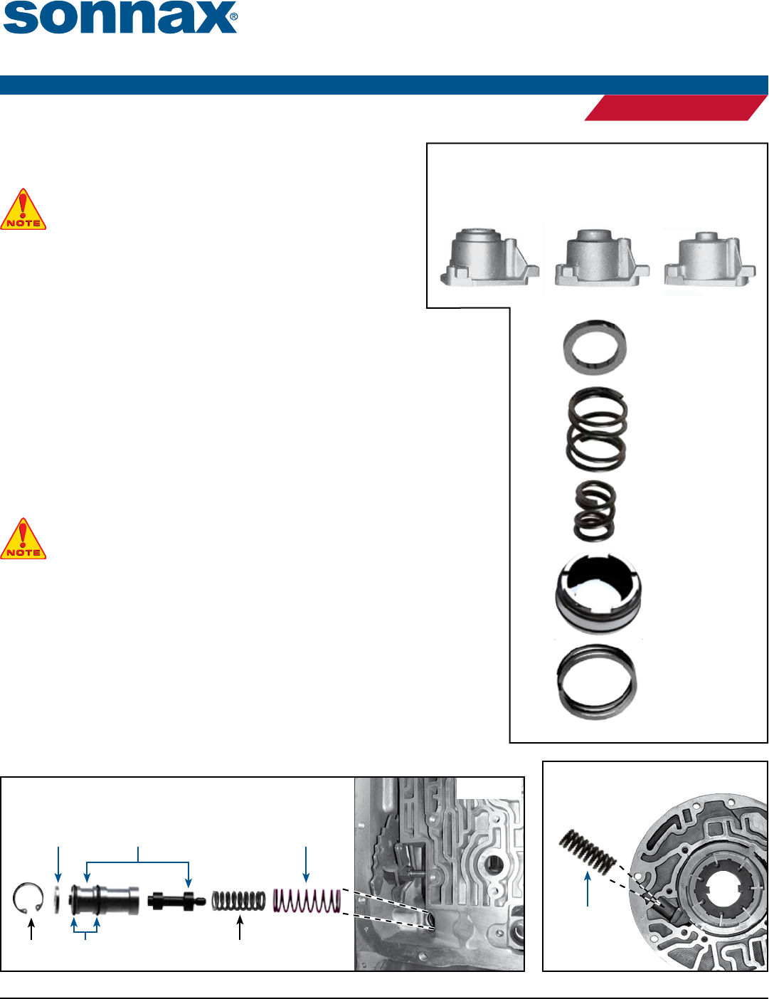
Figure 9
1-2
Accumulator
Waved
Spring
1-2
Accumulator
Piston
with Seals
1-2
Accumulator
Inner
Spring
1-2
Accumulator
Outer
Spring
Accumulator
Housing
Spacer
‘01-Later
Accumulator
Housing
‘94-‘00
Accumulator
Housing
‘93
Accumulator
Housing
Accumulator Parts
6. Pinless 1-2 Accumulator Installation
NOTE: Do not use this accumulator kit with ‘93 housings.
‘01-Later housings need to have the spacer installed,
‘94-‘00 Housings do not need the spacer (Figure 9).
a. Remove piston pin from the 1-2 accumulator housing.
b. OE pin diameter varies. Plug pin hole by driving one appropriately sized
Sonnax steel ball (.236" or .312" dia.) into hole. Discard unused ball.
c. Stake ball in place.
d. Install rubber D-ring toward piston dome. Install PTFE seal toward open end.
e. For '01-later housings, install Sonnax accumulator housing spacer into accumulator body.
f. Install Sonnax inner and outer springs into accumulator body.
g. Set piston pocket opening onto spring, dome toward plate.
h. Install Sonnax waved spring.
Pump Parts
7. PR Boost Valve & Spring Installation
a. Remove OE boost sleeve and springs. Save OE bumper spring for reuse.
WARNING: The OE boost valve sleeve comes in two lengths, depending on year. The
1994-2004 boost sleeve is longer (1.907") and should be replaced with the Sonnax boost
sleeve AND included Sonnax spacer. If spacer is not installed when replacing 1.907"
sleeves, transmission failure will result! For 2005-later applications with 1.810" long OE boost
sleeve, do NOT install Sonnax spacer.
b.
After placing the two O-rings into the grooves on the boost sleeve, pre-lube them
and roll sleeve over bench to resize the O-ring. Assemble correct boost sleeve/spacer
combination, OE bumper spring and Sonnax elevated pressure regulator spring.
c. Insert Sonnax valve into sleeve with nubbed end facing out (Figure 10).
d. Carefully insert sleeve assembly into pump body with the open end toward the two
springs, just deep enough to reinstall OE retainer clip.
8. Pump Slide Spring Installation
Remove both OE pump slide springs from pump housing and replace with Sonnax
spring (Figure 11).
Figure 10
OE Clip
Boost Valve
Assembly
Elevated PR
Spring
O-Rings
Spacer
OE Bumper Spring
Figure 11
High RPM
Pump Slide
Spring
©2016 Sonnax Industries, Inc. HP-4L60E-01-IN 11-22-16
800-843-2600 • 802-463-9722 • F: 802-463-4059 • www.sonnax.com Page 5
PERFORMANCE PACK HP-4L60E-01
Instructions
High Performance TRANSMISSION Parts
PERFORMANCE
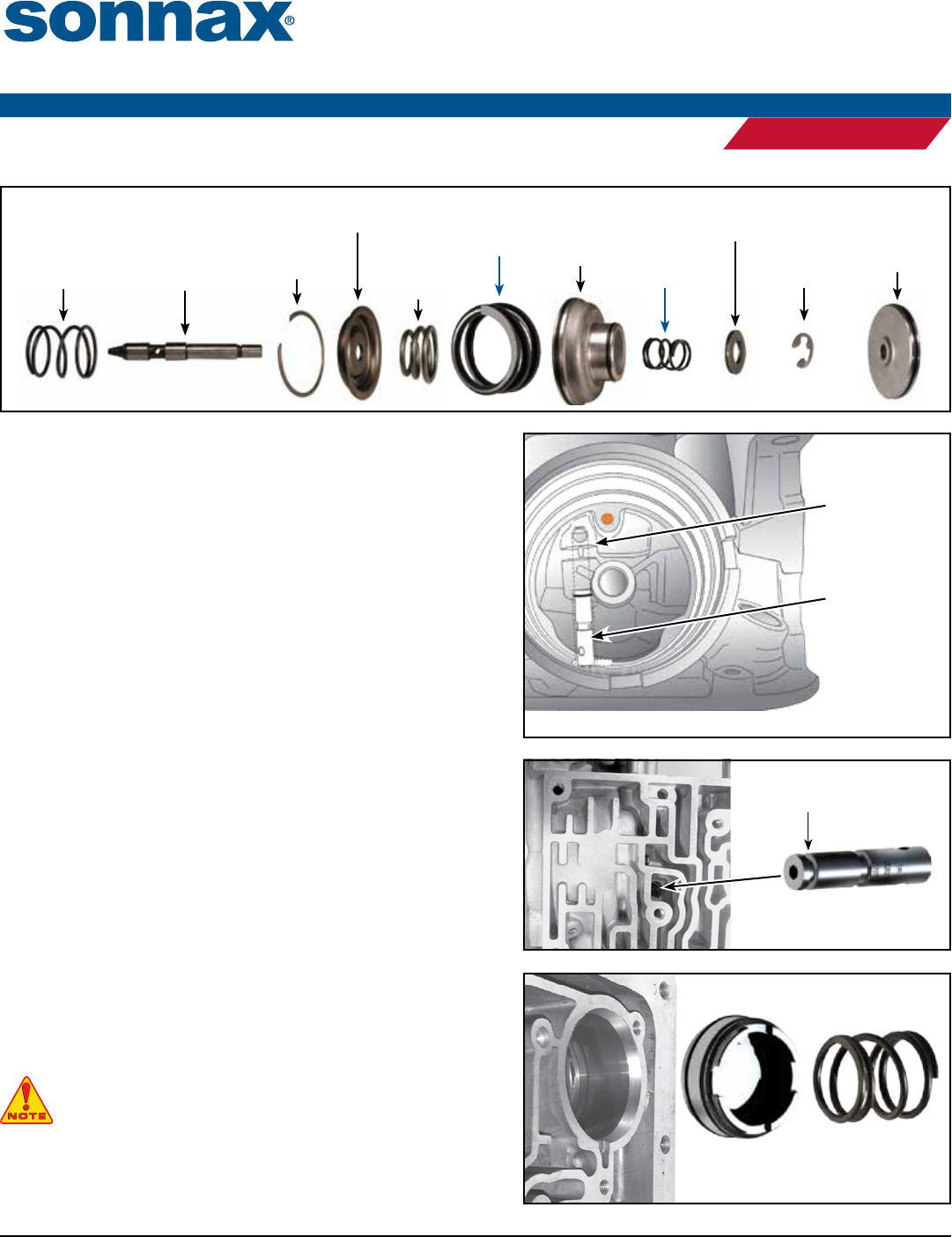
Servo Parts
9. Servo Installation
a. Remove OE servo cushion spring and replace with Sonnax servo
cushion spring (Figure 12).
b. Reinstall the conical OE bumper spring if used in your applica-
tion.
c. Replace OE 4th servo return spring under the washer and C-clip
with Sonnax 4th servo return spring.
d. Install rubber D-rings onto servos. Ensure seals are not twisted in
groove.
Case Parts
10. Servo Release Check Valve Installation
e bore in the case is not a critical diameter for OE manufacturing
purposes, so some variations in the t of the check valve are possible. e
O-ring ensures a positive seal in cases with larger bores. e check valve is
installed between the OE checkball capsule and the separator plate. e
check valve DOES NOT replace the OE checkball capsule (Figure 13).
a. Install the check valve, tapered end rst, into the case. If resistance
is felt, tap the check valve in until ush or just below ush with
the case. If it slides all the way in without resistance, remove and
reinstall with Sonnax O-ring (Figure 14).
b. Run a straight edge over the case to verify the check valve is not
sticking up above the case gasket surface.
11. Pinless 3-4 Accumulator Installation
a. Remove accumulator pin.
NOTE: Pin bore is blind in this location, so
there is no need to plug with any checkball.
b. Install D-ring toward dome with PTFE seal toward open end.
Install dome toward case (Figure 15).
c. Install Sonnax 3-4 accumulator spring.
Servo
Cushion
Spring
Figure 12
4th Servo
Return Spring
OE Bumper
Spring
(some models)
OE Return
Spring
OE Servo
Pin
OE
Retainer
Ring
OE Spring
Retainer
OE 2nd
Piston OE 4th Apply
Piston
OE
Retaining
Clip
OE
Washer
Use OE 3rd
accumulator
capsule.
Sonnax
77701-076
Servo Release
Check Valve
Install Sonnax
check valve into
bore over OE
capsule.
Installation Location Transparent View
Figure 13
3-4
Accumulator
Piston Kit
3-4
Accumulator
Spring
Figure 15
Servo Release
Check Valve
Figure 14
O-Ring
Groove
