SC 01M 01N 01P IN
Sc-01M-01N-01P-In SC-01M-01N-01P-IN SC-01M-01N-01P-IN 3023 instructions part uploads sonnax-dev
2016-10-12
: Sonnax Sc-01M-01N-01P-In SC-01M-01N-01P-IN 1314 file instruction uploads
Open the PDF directly: View PDF ![]() .
.
Page Count: 4
APPLICATIONVW/Audi 01M, 01N, 01P
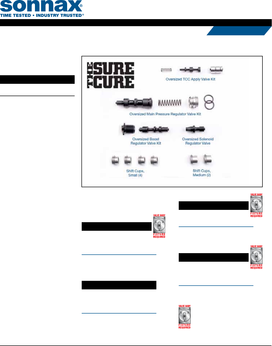
Sure Cure® Kit
Part No.
SC-01M/01N/01P
Valve Body Parts
Oversized Main Pressure
Regulator Valve Kit
119940-03K
Oversized TCC Apply
Valve Kit
119940-04K
Oversized Boost Regulator
Valve Kit
119940-05K
Oversized Solenoid
Regulator Valve
119940-06K
Shift Cup, Small (4)
119940-11
Shift Cup, Medium (2)
119940-10
The following tool kits are required
to install this Sure Cure Kit:
NOTE: Instructions are provided with this tool kit.
Part No.
F-119940-TL3
• Reamer
• Reamer Jig
• Guide Pin
NOTE: For installing oversized main
pressure regulator valve kit 119940-03K.
Part No.
119940-TL4
• Reamer
• Reamer Jig
• Bore Sizing Tool
NOTE: For installing oversized TCC
apply valve kit 119940-04K.
Part No.
F-119940-TL5
• Reamer * Reamer Jig
• Reamer Jig • Adjustment Tool
NOTE: For installing oversized boost
regulator valve kit 119940-05K.
Part No.
F-119940-TL6
• Reamer
• Reamer Jig
• Guide Pin
NOTE: For installing oversized solenoid
regulator valve 119940-06K.
NOTE: Sonnax “F-Tool” kits designed
to service a specic bore require the
VB-FIX, a self-aligning valve body
reaming xture. More information and
instructions can be found online at
www.sonnax.com.
©2016 Sonnax Industries, Inc. SC-01M_Pg1 10-07-16
800-843-2600 • 802-463-9722 • F: 802-463-4059 • www.sonnax.com Page 1
TRANSMISSION PARTS
Instructions
Valve Body Preparation:
1. Remove the boost regulator valve ratcheting end plug as outlined below.
Ratcheting End Plug Removal:
Note: • Prior to removing the ratcheting end plug from the bore, measure and note how deeply it is
installed. The replacement plug should be installed to this same depth to ensure proper line
pressure control. The most accurate method is to insert a slide caliper rod through the hole in the
plastic plug until it bottoms against the control valve. Bring the caliper end toward the plug until
flush. This gives you the spring height adjustment from the plug to the valve. Record this measurement
before removing the plug and duplicate this distance during reassembly to most accurately
duplicate the spring compression setting. If your caliper will not pass through the hole, measure
from the valve body casting surface to the outer face of the OEM plug and duplicate later.
• The adjustment tool may be used during removal of either the OEM or Sonnax ratcheting end
plug at the boost regulator valve bore.
• Using the tool prevents breakage of the 2 anti-rotational tabs. The adjustment tool is provided
in the F-119940-TL5 tool kit.
To remove the ratcheting end plug from the bore, gently insert the cam end of the tool into the valve
body and over the end of the end plug.
2. Remove all other components from the valve body. Save all components at this time. Be sure to keep
individual components of the various line-ups together, to help ensure that matched valve and spring
combinations will be correctly installed together during reassembly. Clean the valve body after disassembly.
Note: Before reaming any bores, inspect the main pressure regulator valve. 01M, 01N, 01P valve inner
spools measure .5935" OD. If your valve inner spools measure .6095" OD, DO NOT CONTINUE. You have an
096, 097, 098 valve body and must order SC-096/097/098 and different tooling to continue with the repair.
Reaming Instructions – Tool Usage: 1. To align the valve body for reaming with all the
F-Series tool kits, follow the VB-FIX instructions.
2. Boost Regulator Bore: From tool kit
F-119940-TL5, use jig F-119940-RJ6 and
guide pin F-119940-GP2, then ream with
reamer F-119940-RM2.
3. Main Regulator Bore: From tool kit
F-119940-TL3, use jig F-119940-RJ5 and
guide pin F-119940-GP4, then ream with
reamer F-119940-RM.
4. Solenoid Regulator Bore: From tool kit
F-119940-TL6, use jig F-119940-RJ7 and
guide pin F-119940-GP3, then ream with
reamer F-119940-RM3.
Note: Extra attention should be paid to alignment
and securing the valve body to the fixture on this
bore. A very smooth action to insert and remove
the guide pin after final securing is a must to pro-
vide easy, on-center reaming.
5. TCC apply valve bore does not require use of
VB-FIX but the fixture may be used to mount
the valve body. From the tool kit 119940-TL4,
insert the reamer jig 119940-DJ4 directly into
the valve body bore, then ream with reamer
119940-RM4.
TORQUE SPECIFICATIONS:
Valve body to case bolts: 108 inch lbs.
Valve body halves: 71 inch lbs.
Pump to stator: 71 inch lbs.
Pump to case: 71 inch lbs.
Oil cooler to case bolts: 26 ft. lbs.
ELECTRONICS:
Solenoids are prone to contamination failures.
Test on a solenoid tester or replace.
On-off solenoid resistance. 60 ohms
(triangular brass insert on the end)
PWM solenoid (TCC/EPC). 5 ohms
(round brass crimped onto end)
All On-Off solenoids are interchangeable –
Sonnax 119952-01.
EV6/ EPC & EV4/TCC are interchangeable –
Sonnax 119954-01
Wiring harnesses become brittle.
Connector issues and intermittent internal
breaks are common.
01M – Sonnax 119957A
01N – Sonnax 119957B
01P – Sonnax 119955C
BUSHINGS:
Inspect all bushings carefully.
Sonnax Bushing Kit 119905-01K
GENERAL NOTES / CAUTIONS
Do not forget to fill the differential on
01M/096 units. These have a separate
sump from the ATF.
Use 80-90 synthetic gear lube. Fill and
check location is the driven speedometer
gear. Gear lube should be visible on half
of the driven gear tooth.
Aftermarket fluid preference is partial
synthetic ATF. Dexron III with an additive may
be sufficient. VW/Audi fluid tends to varnish
easily at higher operating temperatures.
01M/01N/01P ATF level: Remove oil pan
plug, fill at the cap just above pan rail
until fluid comes out pan tube.
High transmission fluid temperatures:
Sonnax suggests the elimination of the OE
antifreeze to ATF cooler mounted on the
transmission.
All computer codes must be cleared
before rebuilt valve body or transmission
is test driven.
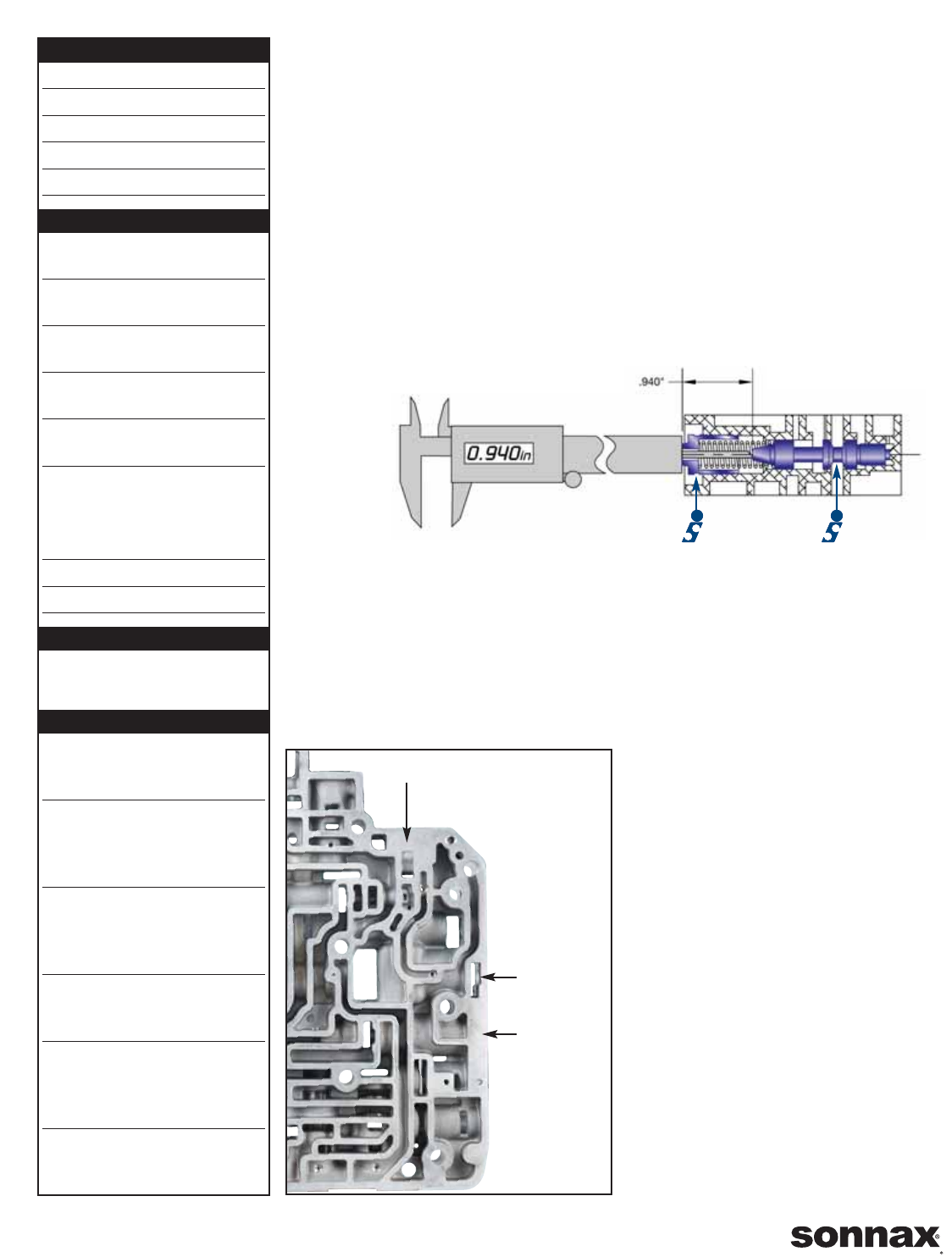
Boost
Regulator Valve
Ratcheting
End Plug
Boost
Regulator
Bore
Main
Regulator
Bore
Solenoid Regulator Bore
04-09-10 SC-01M-01N-01P-IN ©2010 Sonnax Industries, Inc.
Page 2 800/843-2600 • 802/463-9722 • fax: 802/463-4059 • www.sonnax.com
TIME TESTED • INDUSTRY TRUSTED
Reaming Procedures – all bores:
1. Soak the bore and reamer with cutting fluid (Mobilmet S-122, Lubegard Bio-Tap, Tap Magic™, etc.). For best results, provide a con-
tinuous flow of water-soluble cutting fluid (i.e. Mobilmet S-122) during the reaming process.
2. Gently insert the reamer through the jig and into the bore until the cutting tip contacts the first bore to be reamed.
3. Select the correct sized socket to fit the square shank of the reamer, and attach it to a wobble/swivel socket drive.
Note: Once valve body alignment has been established on the VB-FIX, do not disturb or loosen the valve body setting or guide setting in any
way until the reaming process is complete. Be sure to use plenty of continuously supplied cutting fluid while reaming these bores. The large
amount of material being removed is more likely to cause reamer stalling than most operations.
4. The reamer should be turned by hand using a speed handle or by a low rpm, high torque air drill regulated to a maximum of 200 rpm.
5. The reaming action should be clockwise in a smooth and continuous motion, at 60-200 rpm. The reamer should actually pull itself
through the bore, so little or no forward force should be applied.
6. Continue reaming until the reamer stop is reached.
7. Using low air pressure, blow the chips free before removing the reamer.
8. To remove the reamer, turn clockwise while slowly pulling outward on the reamer.
9. Repeat the process until all bores have been reamed. ALL reamed bores should be deburred and polished with Scotchbrite™ on a
drill. Use a stiff wire bent back sharply to hold/ turn the Scotchbrite™. (This process is very important on this valve body, espe-
cially the oversized TCC valve.)
10. Thoroughly clean the valve body. Inspect all bores.
Cautions and Suggestions:
1. Turning the reamer backward will dull it prematurely.
2. Pushing on the reamer will result in poor surface finish and inadequate and sporadic material removal.
3. Never use a crescent wrench, ratchet or pliers to turn the reamer.
4. A dull reamer will cut a smaller hole.
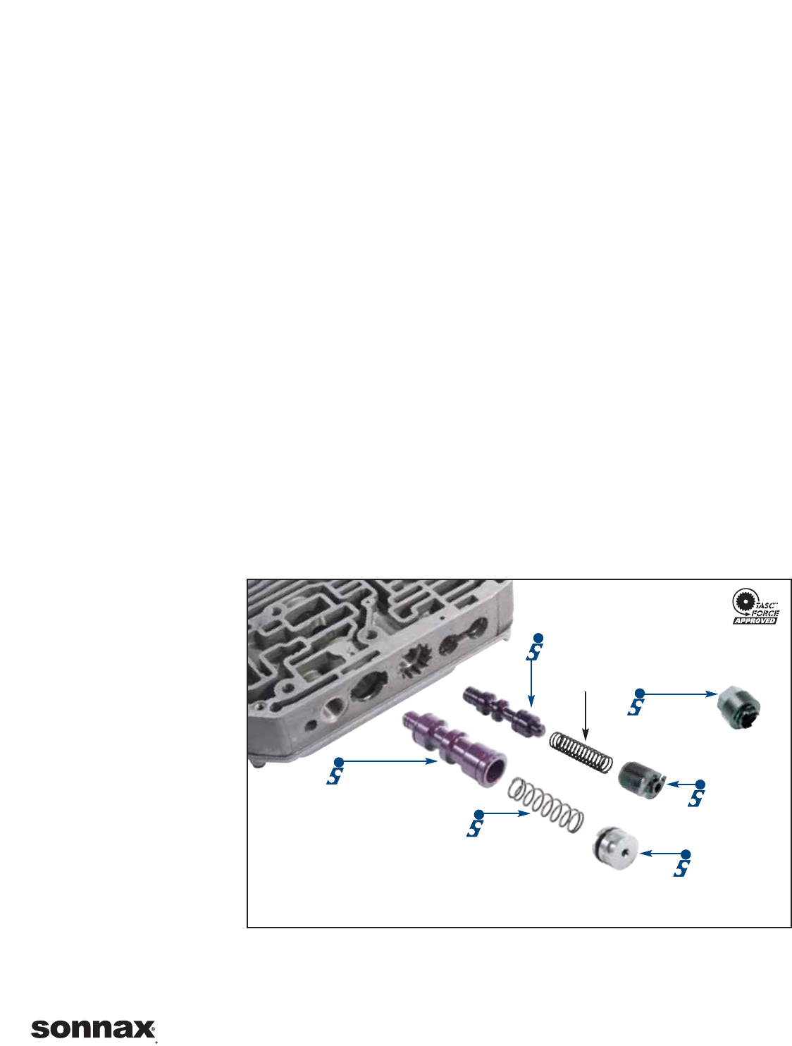
Main Pressure Regulator Valve Installation
Install the Sonnax valve, Sonnax spring and the Sonnax o-ringed end plug and retainer as shown below. Lubricate the bore and o-ringed end
plug prior to assembly and insert into bore slowly to prevent seal damage. An extra o-ring is included in case of damage.
Note: Be sure to use the new end plug and o-ring provided in the kit. They are not the same size as the ones that were removed. Substituting
the original plug or original o-ring will negatively affect line rise.
Boost Regulator Valve Installation
Install the Sonnax valve, OEM spring
and the Sonnax ratcheting end plug
as shown at right.
1. To install the end plug, thread into
the bore until the premeasured
height is again achieved.
2. Adjustments to the base setting may
be required due to variations in the
plug, valve body or improvements
from either regulator bore. Initial
setting on average OEM parts is
.940" measured from the end of
the valve to the outer face of the
plastic adjuster. Turning the adjuster
clockwise will increase boost pressure,
line pressure and create firmer
engagements as well as upshifts
and downshifts. Counter clockwise
reduces line pressure at idle and
results in softer shifts. Each turn is
approximately an 8 psi alteration.
One turn is drastic and we suggest
you go by 1/2 to 1/4 turns. The
outcome of this adjustment is
monitored at line pressure tap.
3. A 5/16" socket may be used while threading the plug into the bore. However, the tool will be needed to turn the plug back out while
adjusting to the correct setting.
4. It is very important to verify line pressure when installation is complete. OEM line in Drive is generally 50-56 psi. Reverse is 95-110 at
idle. To obtain firm engagements or reduce flare, increase line in Drive to 60 (1/2 turn clockwise). Readjust if not within this range.
Boost Regulator
Valve Spring
Main Regulator Valve
Spring
End Plug
w/O-Ring
Ratcheting
Plug
119940-22
Adjustment
Tool
119940-TL9
is included in F-119940-TL5
©2010 Sonnax Industries, Inc. SC-01M-01N-01P-IN 04-09-10
800/843-2600 • 802/463-9722 • fax: 802/463-4059 • www.sonnax.com Page 3
TIME TESTED • INDUSTRY TRUSTED
Note: OE line pressure port is a straight 10 x 1.0mm thread with a flanged plug.
A line pressure adapter can be made from a common 1/8th NPT 45-degree
adapter. Chase male thread on the adapter with 10 x 1.0 thread die. Gently
screw adapter into the case and then screw pressure gauge into adapter.
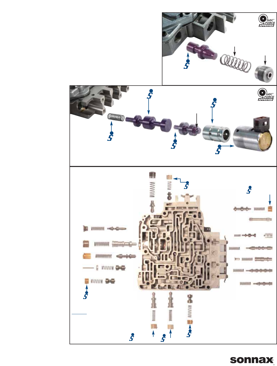
Solenoid Regulator Valve Installation
Install the Sonnax valve with the OEM spring and end plug as shown. OEM end
plug is threaded but this is not an adjustment. Thread in until snug.
TCC Apply Valve, TCC Boost Valve & Sleeve
Installation
Note: Before valve installation, buff the entire bore with Scotchbrite™ on a wire.
1. Place the replacement spring over the stem of the oversized TCC apply valve
and install into the reamed
bore, spring end first.
2. Insert the replacement
TCC boost valve and
sleeve assembly into the
bore, using the photo as a
reference for correct ori-
entation. Stroke this
valve after the solenoid
is installed to ensure it
does not stick.
Note: The replacement TCC
boost valve and sleeve
assembly in this kit MUST be
used with the oversized TCC
apply valve to maintain proper
ratios and valve functions.
For identification purposes,
the replacement TCC boost
valve has a groove on the
outboard-facing end stem.
Reusing the OEM assembly
can result in TCC slippage,
burn-up and complaints.
Final Reassembly
Reassemble the remaining
line-ups using the photo at
right as a guide. Be sure to
replace the 4 small and 2
medium OEM end plugs
with the plugs provided in
this kit.
Note: Make sure the large
end plug in the main regula-
tor bore is the one that came
in this kit. The OEM plug and
o-ring and our standard
119940-12 large end plug
should not be substituted for
this plug that comes with the
oversized main PR valve.
Additionally, for '98-Up valve
bodies the OE K1 actuator
valve shift cup is solid and
not drilled through. DO NOT
USE the Sonnax small shift
cup (119940-11) in this valve
bore. Reuse the OE shift
cup. '97 and earlier units will
use the small Sonnax shift
cup at the K1 actuator bore.
Solenoid
Regulator Valve
Spring
End Plug
Oversized TCC
Apply Valve
TCC
Boost Valve
TCC Boost Sleeve
Also Available
119954-01 Converter
Clutch Solenoid
Spring
Identification
Groove
K3/Manual Low Valve
Main Pressure Regulator Valve
Boost Regulator Valve
K2 Actuator Valve
K1 Actuator Valve
Manual Valve
K3 Shift Valve
B1 Apply Valve
K1/B1 Shift Valve
B2 Shift Valve
2-3 Regulator Valve
B2 Actuator Valve
Converter Regulator Valve
119940-11 119940-11
TCC Apply Valve Kit
119940-10
119940-11
'97 & Earlier
119940-10 119940-11
K1 Cushion Valve
3-4 Regulator Valve
If working on a '98-Up valve body
DO NOT replace the OE K1 actuator
shift cup with the Sonnax small shift
cup (119940-11). Reinstall the OE
shift cup. See final reassembly note.
04-09-10 SC-01M-01N-01P-IN ©2010 Sonnax Industries, Inc.
Page 4 800/843-2600 • 802/463-9722 • fax: 802/463-4059 • www.sonnax.com
TIME TESTED • INDUSTRY TRUSTED
