SC AODE 4R75E IN
2017-09-15
: Sonnax Sc-Aode-4R75E-In SC-AODE-4R75E-IN 4472 instructions part uploads
Open the PDF directly: View PDF ![]() .
.
Page Count: 8
PART NUMBER SC-AODE-4R75E INSTRUCTION BOOKLETPART NUMBER SC-AODE-4R75E INSTRUCTION BOOKLET
4R70E, 4R70W, 4R75E, 4R75W, AODE
SURE CURE KIT
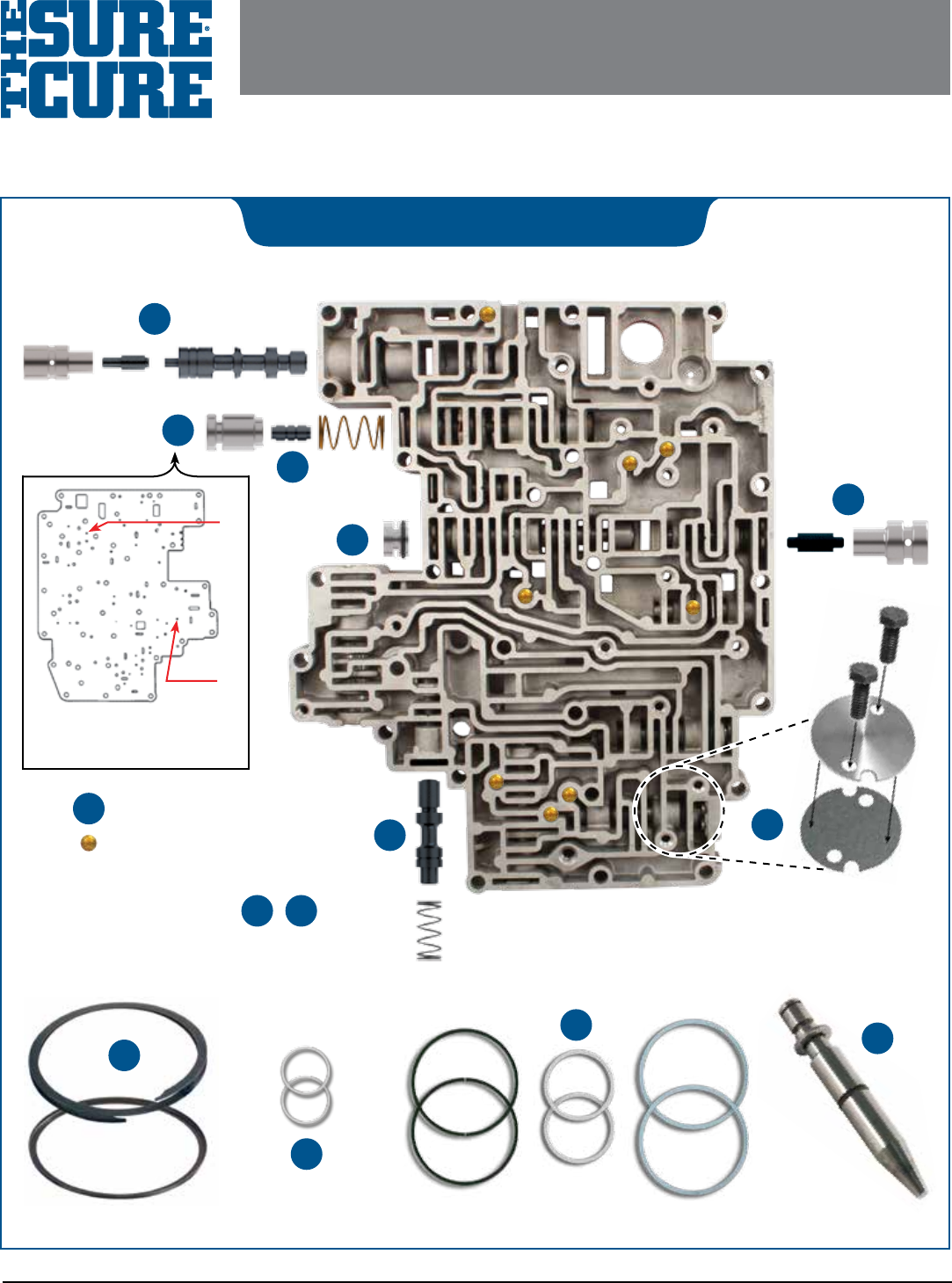
Parts are labeled here in order of installation. See other side of sheet for details on Sure Cure kit contents.
See Sure Cure instruction booklet for detailed installation steps.
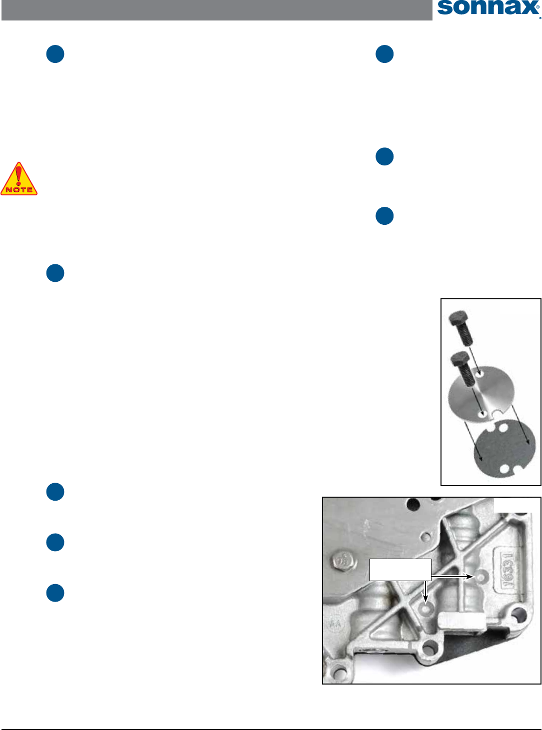
VALve Body install Diagram
12
4
5
3
6
7
8
10
14
11
13
A
B
To ensure bypass/TCC system
has full control, drill "A" & "B"
holes out to .062".
9
Eight checkballs to
install, see locations
on valve body.
See Technical booklet for installation details during overhaul.
1
2
Reference page 3 in
technical booklet.
©2017 Sonnax Industries, Inc. SC-AODE-4R75E-IN 09-15-17
800-843-2600 • 802-463-9722 • F: 802-463-4059 • www.sonnax.com Page 1
09-15-17 SC-AODE-4R75E-IN ©2017 Sonnax Industries, Inc.
Page 2 800-843-2600 • 802-463-9722 • F: 802-463-4059 • www.sonnax.com
4R70E, 4R70W, 4R75E, 4R75W, AODE SURE CURE KIT
Instruction Booklet
TIME TESTED • INDUSTRY TRUSTED
Step Install Oversized Solenoid
Regulator Valve & Spring
Packaging Pocket 5
• Valve • Spring
Step Replace Overdrive Servo
Regulator Valve & Sleeve
NOTE: '01–Later applications only.
Remove OE clip and save for reuse. Remove and discard OE overdrive
servo regulator valve and sleeve.
NOTE: Remove the inboard overdrive servo regulator valve and ensure
that it is free in its bore. The inboard valve is commonly stuck as OD
servo retaining ring often breaks and pieces of the snap ring lodge in
this bore.
Packaging Pocket 6
• Valve • Sleeve
Step Replace OE Checkballs
Refer to page 1 for locations.
Packaging Pocket 7
• Checkballs (8)
Step Install Valve Body
Retainer Plate
NOTE: Used on '01–later applications only. Installation requires
drilling of separator plate and valve body casting so it can be
threaded. Reference page 6 for detailed instructions.
Packaging Pocket 8
• Retainer Plate • Gasket • Bolts (2)
7
8
9
10
Sure Cure Contents & Installation Steps
Step Ream Main Pressure
Regulator Valve Bore
Step Ream Solenoid Regulator
Valve Bore
PART INSTALLATION: To implement best practices and avoid chip
contamination, wait until all valve body reaming operations are nished
before installing Sonnax products. Detailed installation instructions are
explained later in this booklet.
F-TOOL REAMING: Visit Sonnax web site www.sonnax.com for gener-
al F-Tool reaming xture instructions, as well as best practices for bore
preparation, cautions and suggestions on bore reaming.
Step Install Oversized Main PR
Valve, Oversized Boost
Valve & Sleeve
Reuse OE Spring. Reference page 4 for detailed instructions.
Packaging Pocket 1
• Oversized Main PR Valve • Boost Valve • Boost Sleeve
Step Replace Bypass Clutch
Control Valve Plunger,
Sleeve & Spring
Packaging Pocket 2
• Plunger • Sleeve • Spring
Step Perform Separator Plate
Modications
Packaging Pocket 3
• Drill bit, .062" (not shown)
Step Replace 2-3 Shift Valve
End Plug
Remove OE clip and save for reuse. Remove and discard OE 2-3 shift
valve end plug. Install O-ring on Sonnax end plug in shallow groove.
Lubricate with Sonnax O-Lube or equivalent, roll on bench to size.
Install O-ringed plug into bore, O-ringed land rst. Reinstall OE clip.
Packaging Pocket 4
• Plug • O-Rings (2) 1 extra
1
2
3
4
5
6
4R70E, 4R70W, 4R75E, 4R75W, AODE SURE CURE KIT
Instruction Booklet
©2017 Sonnax Industries, Inc. SC-AODE-4R75E-IN 09-15-17
800-843-2600 • 802-463-9722 • F: 802-463-4059 • www.sonnax.com Page 3
TIME TESTED • INDUSTRY TRUSTED
Step Install Intermediate Clutch
Spiral Retaining Ring
Reference page 6 for detailed instructions.
Packaging Pocket 9
• Spiral Retaining Ring • Locking Ring
Step
Replace Output Shaft Seals.
Inspect Direct Piston &
Direct Clutch Drum.
Reference page 7 for detailed instructions.
Packaging Pocket 10
• Output Shaft Seals (2)
Step Install Pump Cover &
Input Shaft Seals
NOTE: There are 2 types of rings for the stator
'02-Earlier and '03-Later.
Reference page 7 for detailed instructions.
Packaging Pocket 11
• Pump Cover Seals; Early (2), Late (2) • Input Shaft Seals (2)
Step
Replace Overdrive Servo Pin
Reference page 8 for detailed instructions.
Packaging Pocket 12
• Servo Pin • O-Rings; Large (1), Medium (1)
11
12
13
14
Sure Cure Steps During Transmission Overhaul
09-15-17 SC-AODE-4R75E-IN ©2017 Sonnax Industries, Inc.
Page 4 800-843-2600 • 802-463-9722 • F: 802-463-4059 • www.sonnax.com
Figure 3
Sonnax PR valve replaces
both OE valve styles
found in '96-later units.
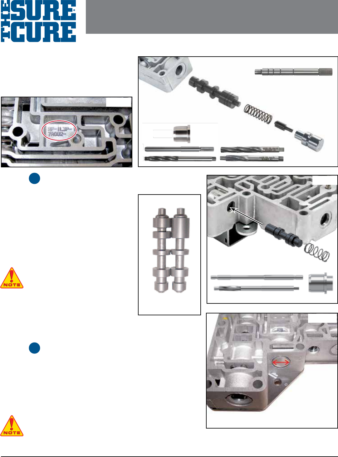
Step Ream Pressure Regulator
Valve Bore (Figure 2)
1. Disassembly
a. Remove OE retainer and save for reuse.
b. Remove and discard OE boost valve and sleeve.
c. Remove OE pressure regulator valve spring and
save for reuse.
d. Remove and discard OE pressure regulator valve.
2. Ream Bore
NOTE: This bore requires the use of tool kit
76948-TL4 or tool kit F-76948-TL and the
alignment xture VB-FIX (not included in this kit).
NOTE: Sonnax 76948-BST can be used if necesary to
ensure that the pressure regulator valve moves freely.
NOTE: The oversized valve in this kit will also service the
split spool design shown (Figure 3).
NOTE: Do not install valves at this time. Wait until all reaming operations are nished.
Step Ream Solenoid Regulator
Valve Bore (Figure 4)
1. Disassembly
a. Remove OE retainer and save for reuse.
b. Remove and discard OE spring and solenoid regulator valve.
2. Reaming Bore
NOTE: This bore requires the use of tool kit F-76948-TL47 and the alignment
xture VB-FIX (not included in this kit).
1
2
OE
Spring
Pressure
Regulator
Valve
AODE
Valve Body
Boost
Sleeve
Tool Kit
F-76948-TL
Requires
VB-FIX
Tool Kit: 76948-TL4
Does not require VB-FIX
76948-BST
Boost
Valve
Figure 2
Valve Body Verication
Verify that this kit ts your valve body. Rough forging
must begin with RF-F6 or 1L3P located below sti-
ener plate (Figure 1). is kit ts '96–later units. It will
NOT work on '91–'95 units.
Figure 1
Figure 5
Line on back of sleeve
indicates the two orice
hole locations, placed at
3 & 9 o’clock position.
4R70W
Valve Body Spring
Valve
Tool KIt
Figure 4
PART NUMBER SC-AODE-4R75E INSTRUCTION BOOKLETPART NUMBER SC-AODE-4R75E INSTRUCTION BOOKLET
4R70E, 4R70W, 4R75E, 4R75W, AODE
SURE CURE KIT
4R70E, 4R70W, 4R75E, 4R75W, AODE SURE CURE KIT
Instruction Booklet
©2017 Sonnax Industries, Inc. SC-AODE-4R75E-IN 09-15-17
800-843-2600 • 802-463-9722 • F: 802-463-4059 • www.sonnax.com Page 5
TIME TESTED • INDUSTRY TRUSTED
Step Install Oversized Main
Pressure Regulator Valve,
OE Spring & Oversized
Boost Valve & Sleeve
a. Install Sonnax oversized main pressure regulator valve, smaller diameter rst.
b. Reinstall OE pressure regulator valve spring.
NOTE: The small OE boost spring was eliminated in later applications and is not
required. If your application originally had the spring, it may be reinstalled into the
Sonnax boost assembly if desired. Use of the spring will provide slightly
quicker Reverse line rise pressure.
c. Install Sonnax boost valve assembly into bore, ensuring sleeve snout enters
OE spring I.D.
d. Reinstall OE retainer.
Step Replace Bypass Clutch
Control Valve Plunger,
Sleeve & Spring (Figure 5)
a. Remove OE clip and set aside for reuse.
b. Remove and discard OE plunger sleeve, plunger valve and spring.
c. Remove plunger valve from Sonnax sleeve, set aside for reuse.
d. With enclosed Sonnax drill bit, drill thru existing Sonnax sleeve cross-orice
hole and out other side of sleeve. Remove debris and burrs. Reinstall Sonnax
plunger into sleeve.
e. Install Sonnax orange spring and plunger valve and sleeve assembly into
bore and draw a line on the back of the sleeve indicating the two orice hole
locations and place at the 3 and 9 o'clock position(Figure 5).
f. Reinstall OE clip.
Step Perform Separator Plate
Modications
Step Replace 2-3 Shift Valve
End Plug
Step Install Oversized Solenoid
Regulator Valve (Figure 4)
a. Ensure valve bore and body are clean and clear of debris.
b. Install Sonnax valve, longer spool end pointed inward.
c. Install Sonnax spring, ensuring it seats over outboard valve stem.
d. Compress spring and reinstall OE retainer.
3
4
5
6
7
Step Replace
Overdrive Servo
Regulator Valve
& Sleeve
Step Replace OE
Checkballs
Step Install Valve
Body Retainer
Plate Kit (Figure 6)
1. Tools Required
• 13/64" or #9 sharp
drill bit
• 1/4" and 5/16"
drill bits
• 6.0mm x 1.0mm
thread tap
2. Installation &
Assembly
a. Install the separator
plate onto the valve
body and align the
plate with the origi-
nal alignment bolts.
8
9
10
Figure 6
Retainer plate,
gasket
and bolts.
Underside of 4R70W Valve Body
2 Cast in-place
bolt holes
Figure 7
09-15-17 SC-AODE-4R75E-IN ©2017 Sonnax Industries, Inc.
Page 6 800-843-2600 • 802-463-9722 • F: 802-463-4059 • www.sonnax.com
4R70E, 4R70W, 4R75E, 4R75W, AODE SURE CURE KIT
Instruction Booklet
TIME TESTED • INDUSTRY TRUSTED
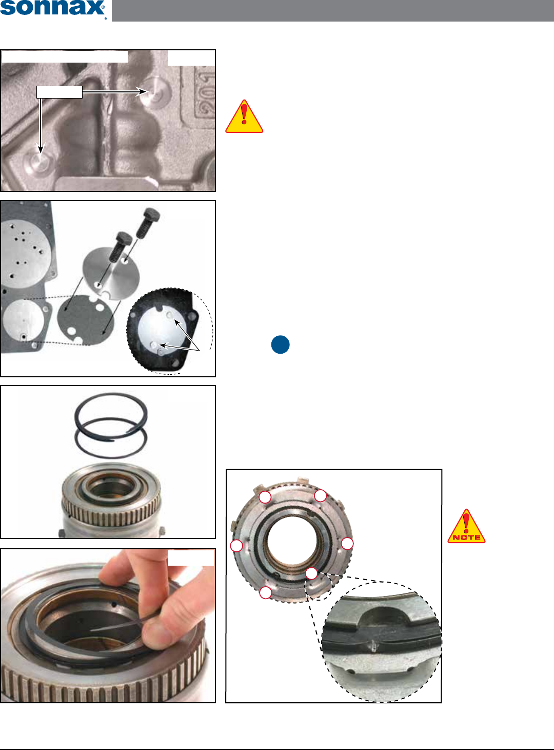
b. Locate the two cast in-place bolt hole locations on the underside of the valve
body as shown in (Figure 7).
c. In a drill press use a 5/16" drill bit to clean up the cast in-place bolt hole loca-
tions and establish a true center for drilling further with the 13/64" or #9 drill.
WARNING: Do not drill deeper than 1/16" with the 5/16" drill bit (Figure 8).
d. After true center is established, use a 13/64" or #9 drill bit to drill all the way
through the valve body AND separator plate with a piece of wood underneath
to prevent the plate from deforming as the drill bit cuts through.
e. Remove the separator plate and enlarge the two drilled holes with a 1/4" drill
bit. De-burr the new holes in the separator plate.
f. With a 6.0 x 1.0mm thread tap, cut new threads in the drilled holes in the
valve body. De-burr the gasket surface, making sure there are no high spots.
g. Install Sonnax checkballs using the locations on page 1.
h. Assemble the valve body gaskets and separator plate using normal procedures.
i. Install the Sonnax gasket, valve body retainer plate and two screws and torque
to 80-100 in-lb. (9-11Nm.) (Figure 9).
The following steps are to be performed during unit overhaul:
Step
Install Intermediate Clutch
Spiral Retaining Ring
1. Disassembly
Remove and discard the OE retaining ring from the intermediate roller clutch or
mechanical diode assembly.
2. Installation
a. Install the locking ring, cup side facing up as shown in (Figure 10).
b. Walk the spiral ring
into the retaining groove
as pictured (Figure 11).
NOTE: The locking
ring may need to be
moved for correct
spiral ring positioning.
c. Make sure the spiral
ring is fully seated in
the groove all the way
around the assembly.
d. Stake the locking
ring in six equally
spaced places around
the outside as shown
(Figure 12).
WARNINGWARNING
WARNINGWARNING
11
Bolts
Retainer
Plate
Gasket
Proper position of
retainer plate
sitting on
valve body.
Figure 9
Drill
& Tap
Figure 10
Spiral Ring
Locking Ring
Drum
Figure 11
Figure 8
Underside of 4R70W Valve Body
Partial Drill
Figure 12
3
6
1
5
4
2
Proper Staking
Technique
Proper Staking
Sequence
4R70E, 4R70W, 4R75E, 4R75W, AODE SURE CURE KIT
Instruction Booklet
©2017 Sonnax Industries, Inc. SC-AODE-4R75E-IN 09-15-17
800-843-2600 • 802-463-9722 • F: 802-463-4059 • www.sonnax.com Page 7
TIME TESTED • INDUSTRY TRUSTED
Figure 14
Checkball
Location
Direct
Piston
Figure 15
No Leaks
Here
Figure 13
Seals
Output Shaft
Figure 16
Pump Cover
Seals
Input shaft
removed from
the forward drum.
Selective Seals:
Early = .110" thick
Late = .083" thick
Input Shaft
Seals
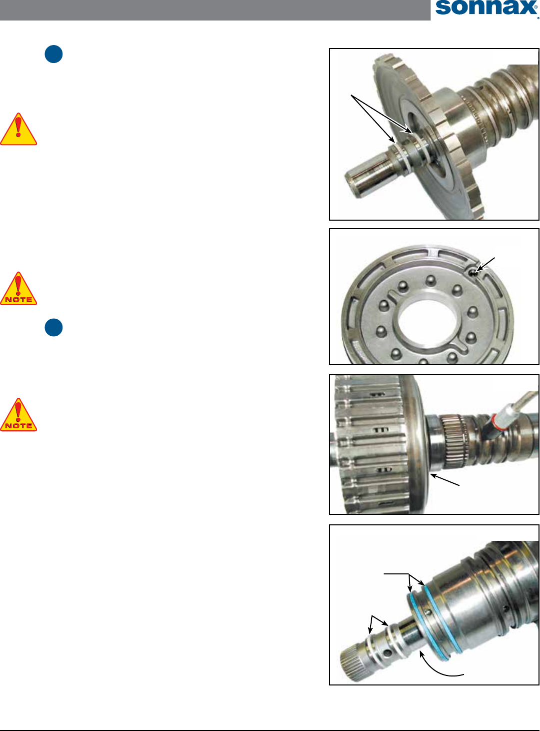
Step Install Output Shaft Seals
1. Disassembly & Inspection
a. Remove and discard the OE seals on the output shaft and replace with the
Sonnax seals as shown (Figure 13).
CAUTION: Don't nick the sealing ring lands as this can cause ring damage.
b. Inspect the checkball in the direct piston (Figure 14) as it is prone to sticking.
Clean and ush with solvent or WD-40® and reseat with a small punch and
hammer.
2. Installation & Testing
a. Assemble the direct clutch drum onto the output shaft (Figure 15).
c. Squirt ATF into the feed hole for direct clutch feed.
d. Apply 30–60 psi of air pressure into the feed hole.
e. Verify that there are no leaks
NOTE: If there are leaks, look for a worn bushing in the drum or leaks in the
ring grooves or the check ball seat.
Step Install Pump Cover
& Input Shaft Seals
1. Installation
a. Install seals onto the pump cover (Figure 16).
NOTE: Two sets of seals are included. Select the correct size/style for the applicat-
ion. The early style is a solid ring (.110" width), the late style is a butt-cut ring
(.083" width). Sizing of the early/solid style is required after installation. A mixture
of ATF and STP can be used to lubricate the solid seals while sizing with nger pressure.
b. Press input shaft out of the Forward drum. Sand ring surface lighty with
320 grit sand paper, using a crosshatch pattern (Figure 19).
c. Install solid seals onto the input shaft. Resize with your ngers. Pre-lube seals
and install into the stator for nal sizing.
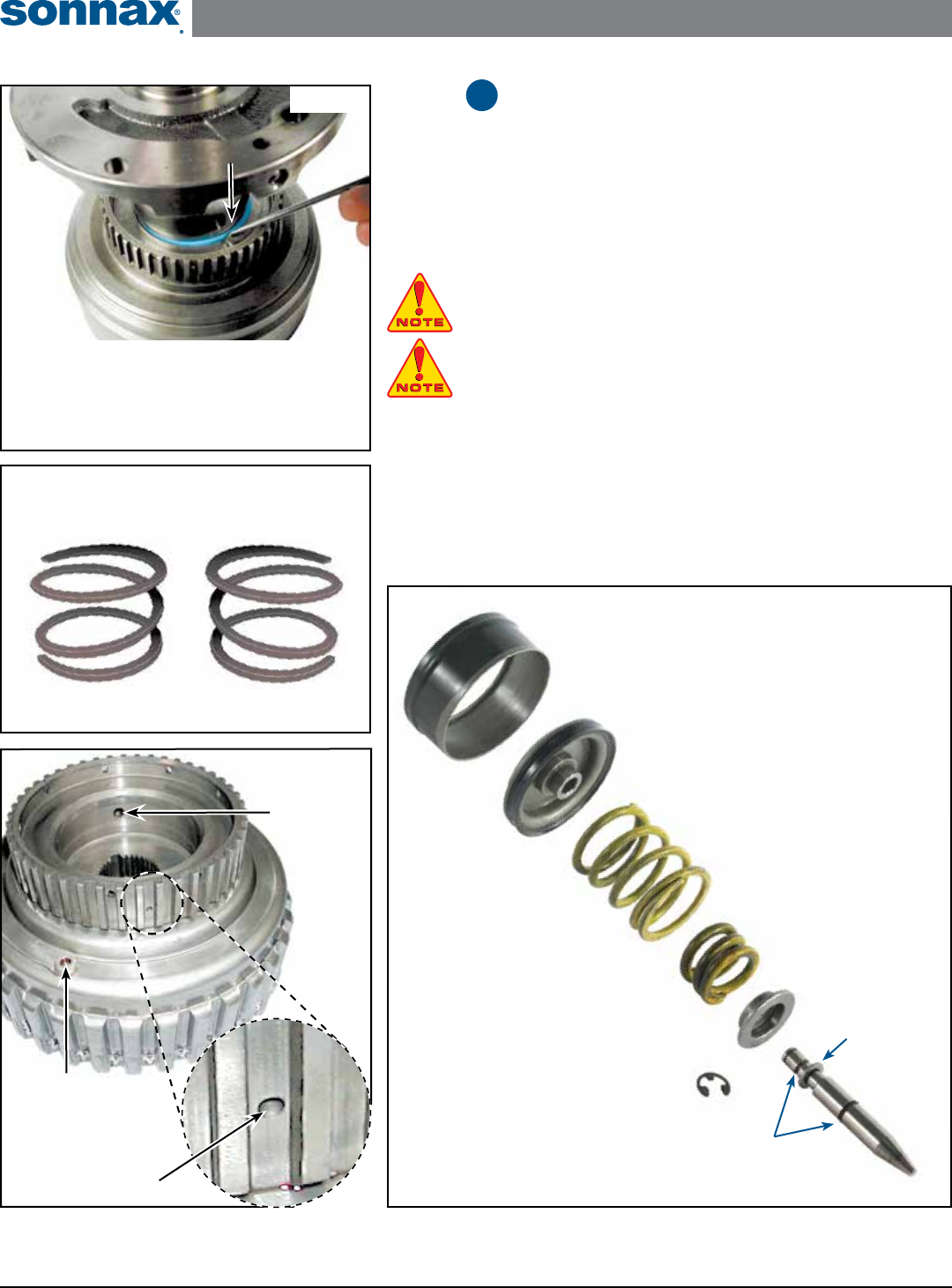
2. Inspect & Verify
b. Inspect the check balls in the Forward drum shown (Figure 19), as they are
prone to sticking. Flush with solvent or WD-40® . Also be sure that the orice
shown, is free of debris that can come from parts washers.
e. An AOD Forward drum can be used to size the early stator seals (Figure 17).
e seals can also be sized with the Forward drum, although it may take a little
longer. Carefully use the back of a pick to work the seal into the drum and let
sit for a while so the seal will stay conformed.
f. Verify correct Forward piston return spring for the application you are working
on (Figure 18).
12
CAUTIONCAUTION
CAUTIONCAUTION
13
09-15-17 SC-AODE-4R75E-IN ©2017 Sonnax Industries, Inc.
Page 8 800-843-2600 • 802-463-9722 • F: 802-463-4059 • www.sonnax.com
4R70E, 4R70W, 4R75E, 4R75W, AODE SURE CURE KIT
Instruction Booklet
TIME TESTED • INDUSTRY TRUSTED
Figure 17
Use an AOD Forward drum to use as sizing tool, as it has
a larger bevel on it for the seals. You will need to remove
the input shaft (early seals only).
Set the stator down onto the AOD drum. Work the edges
of the seals with pick and ease the stator down into the
drum until you need it for assembly later.
Figure 18
Verify correct forward piston
return spring is used.
Clockwise
Wind
2000–Earlier
Counter Clockwise
Wind
2001–Later
Step Replace Overdrive
Servo Pin (Figure 20)
a. Use bore brush to remove sharp edges of overdrive servo pin bore in case.
b. Install O-rings on Sonnax servo pin.
c. Lubricate O-rings and roll pin on clean at surface to size O-rings into pin
grooves.
TECH TIP: If a rmer 3-4 shift is desired, place Sonnax washer on pin against
shoulder to pre-load spring.
NOTE: Following step is easier if piston is compressed in bench vise to facilitate
retaining clip installation.
d. Install OE spring seat followed by springs, piston and retaining clip.
e. Set servo travel according to OE specications.
14
Figure 20
O-Rings
Washer
Overdrive
Servo Pin
Piston
Sleeve
Servo
Piston
Large
Spring
Small
Spring
Spring
Retainer
Retainer
Plate
Figure 19
Sand Here
• 1st Checkball
• 2nd Checkball is located
inside drum under piston.
This orfice ends up full of
debris when run through
parts washer. Be sure to clean.
Forward
Clutch
Drum
