TOY181 Tech Install
2018-07-26
: Sonnax Toy181-Tech-Install TOY181-Tech-Install 4170 instructions part uploads
Open the PDF directly: View PDF ![]() .
.
Page Count: 2
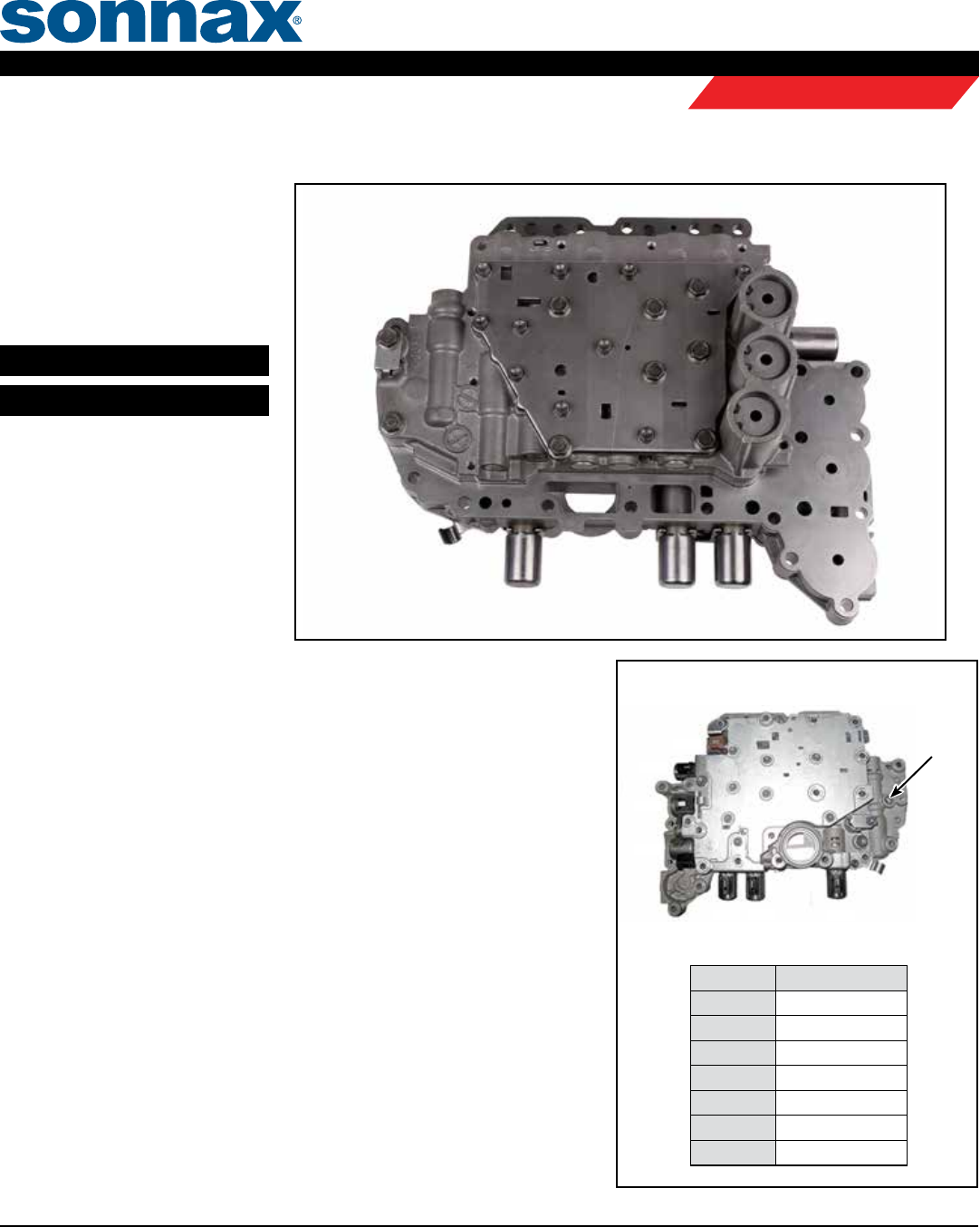
U151E, U151F, U250E
Remanufactured
Valve Body
(’04–’16)
Part Nos.
TOY181
TOY181-RMN
Valve Body Installation Tips
1. Verify Case Accumulator Pistons & Springs are Installed Correctly
Common spring colors:
• C2 (Closest to bell housing) = Yellow
• C3 (Middle) = Plain/No color
• B3 (Rear) = Purple (both inner and outer)
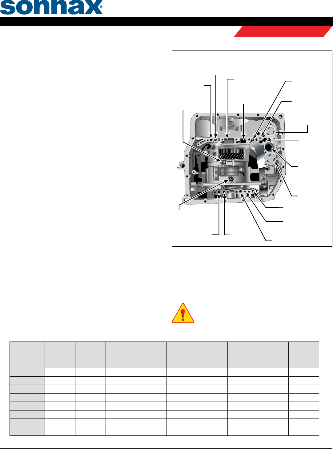
2. Air Check
While valve body is out, air-check indicated circuits (Figure 2) using low,
regulated air pressure. is will help you discover any issues prior to installing the
remanufactured valve body.
3. Install Valve Body onto Case
a. Install drain back checkball and spring into case, spring rst (Figure 2).
b. Verify B1 and B2 apply seals are in the case locations.
c. Align slot in manual valve with manual linkage.
d. Assemble valve body on case and torque bolts to 11 Nm or 8 ft-lb.
e.
Connect wire harness to solenoids and install temperature sensor (Figure 1). Assemble
bracket into temperature sensor slot and torque bolt to 6.6 Nm or 58 in-lb.
f. Install lter and three retaining bolts and torque to 11 Nm or 8 ft-lb.
g. Assemble pan gasket and pan onto transmission case and torque bolts to 7.8 Nm or
69 in-lb.
DSL
SL2
S4
SR
SL3 SLT SL1
Temperature
Sensor
Location
Solenoid Color
SL1 White & Black
SLT Green & Gray
SL3 Red & Blue
SR Purple
S4 Yellow
SL2 Green & Brown
DSL Light Blue
Common Internal Wire Colors
Figure 1
U151 Solenoid ID
©2018 Sonnax Transmission Company, Inc. • A Marmon / Berkshire Hathaway Company TOY181-TECH-INSTALL 07-25-18
866-243-8829 • 856-848-0908 • F: 856-848-1080 • www.sonnax.com Page 1
REMANUFACTURED VALVE BODIES
Tech & Install Tips
Valve Body Installation Tips (continued)
4. Fluid Fill & Road Test
a. Fill transmission with Toyota WS transmission uid to factory spec.
b. Let engine run to warm transmission uid to approximately 175°.
c. Install scan tool to verify transmission uid temp is achieved.
NOTE: This function must be done with a capable scan tool.
d. Reset transmission memory with capable scan tool. (Battery
disconnect will not reset.)
e. Road test vehicle performing 10–15 upshift and downshift
cycles through all ve speeds.
NOTE: A small 2-3 upshift are or overlap issue, clunk into 4th Gear and
a 3-2 downshift clunk is common during adaptive relearn. This condition
will typically resolve itself within the 10–15 shift cycles after reset is
performed.
Transmission Diagnostic Tips
is remanufactured valve body has been through a rigorous inspec-
tion and rebuild process, then a comprehensive, functional hydraulic
and electronic test to ensure it meets OE performance and quality. It
is designed to eliminate many pressure-, shift- and converter-related
complaints, but will not correct complaints that stem from other
areas of the transmission.
e following are common areas of failure or root causes for symp-
toms that could be attributed to valve body issues that should also
be examined or addressed during your transmission build. A brake
and clutch application chart (Figure 3) is below for additional aid in
diagnosing problems.
• 5-4 Downshift clunk can be caused by C1 clutch piston
debonding.
• 2-3 Upshift flare and or binding can be caused by sealing ring
problems in the rear cover.
• This can cause premature C0 clutch failure.
A bind-up during 2-3 upshift can be caused by bad speed sensors.
Shift quality complaints can also be caused by:
• Clutch and brake clearance issues
• Low battery voltage and poor battery grounds
• Bushing/bearing failure and overheat can be caused by case
bearings turning, evidenced by bits of aluminum debris in ATF.
NOTE: The case bearing has been known to spin out on high
mileage units, causing ne metal to build up which can hang
up solenoids and valve trains in the valve body.
Clutch & Brake Application Chart Figure 3
Gear Range
FWD
Clutch
C1
REV
Input
Clutch
C2
Direct
Clutch
C0
U/D
Clutch
C3
2nd
Brake
B1
L/R
Brake
B2
U/D
Brake
B3
No. 1
One-Way
Clutch
F1
No. 2
One-Way
Clutch
F2
Park ON
Reverse ON ON ON
Neutral ON
D-1st Gear ON ON ON ON
D-2nd Gear ON ON ON ON
D-3rd Gear ON ON ON ON
D-4th Gear ON ON ON ON
D-5th Gear ON ON ON
Figure 2
TOYOTA/LEXUX U150/U250
PRELIMINARY INFORMATION
SOLENOID INTERNAL HARNESS AND CONNECTOR I.D.
1
2
3
4
5
613
12
11
10
9
8
7
13 PIN
CONNECTOR
Terminal Function Internal wire color
1 THO (temp +) Orange
2SLT + Green
3 S4+ Yellow
4 SL3+ Red
5Sl2+ Green
6 SL1+ White
7 E2(temp-) Orange
8SLT- Grey
9 SR+ Purple
10 DSL+ Light Blue
11 SL3- Blue
12 SL2- Brown
13 SL1- Black
TCC Apply
B2 Clutch
1st Reverse
Pump
Pressure
TCC Release
Forward Clutch
Drain-Back
Check Valve
C3
Accumulator
Pump Suction
B3
Accumulator
B1 Clutch
2nd Brake
C3 UD Clutch
B3 UD
Brake
Clutch
C2 Reverse Clutch
Lube
C0 Direct Clutch
Lube Pressure
C2 Accumulator
Air Check Locations and Identiers
©2018 Sonnax Transmission Company, Inc. • A Marmon / Berkshire Hathaway Company TOY181-TECH-INSTALL 07-25-18
866-243-8829 • 856-848-0908 • F: 856-848-1080 • www.sonnax.com Page 2
U151E, U151F, U250E VALVE BODY TOY181, TOY181-RMN
REMANUFACTURED VALVE BODIES
Tech & Install Tips
