U140E U241E ZIP IN
2017-01-05
: Sonnax U140E-U241E-Zip-In U140E-U241E-ZIP-IN 3047 instructions part uploads
Open the PDF directly: View PDF ![]() .
.
Page Count: 10
PART NUMBER U140E-U241E-ZIP QUICK GUIDE
Lower
Valve Body
6
Plastic Checkball
Shown in 11 places.
3
Small
3
Large
3
Medium
Upper Valve Body
2
3
Small
3
Large
3
Small
3
Small
3
Small
1
3
Small
NOTE: Before
removing OE boost
sleeve, take note of
the adjustable step/
pin location and
ensure the Sonnax
sleeve is installed
at the same height/
location. Failure to
do so will result in
incorrect line rise.
4
Cutaway shows a
side view of lower
valve body with
Sonnax boost valve
kit installed.
Only use here in
models that have a
hole in the plate at
this location.
Install with open end out.
5
©2016 Sonnax Industries, Inc. U140E-U241E-ZIP-Guide_B 11-03-16
800-843-2600 • 802-463-9722 • F: 802-463-4059 • www.sonnax.com Page 1
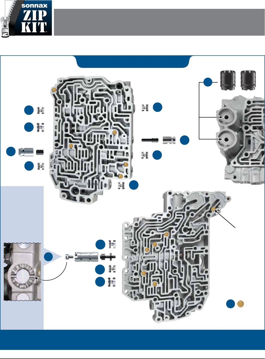
TOYOTA U140E/F, U240E, U241E
ZIP KIT
Parts are labeled here in order of installation. See other side of sheet for details on Zip Kit contents.
installation Diagram
In addition to general rebuilding tips and technical information, the technical booklet included in this kit contains vacuum
testing and additional repair options for higher mileage units or for repairing specic complaints which are beyond the
scope of this kit.
U140E/F, U240E, U241E ZIP KIT Quick Guide
Zip Kit Contents & Installation Steps
Step Replace OE Clutch
Apply Control Sleeve
& Plunger Valve
Packaging Pocket 1
• Plunger Valve
• Plunger Sleeve
Step Replace OE Lockup
Control Sleeve
& Plunger Valve
NOTE: Reuse OE spring if applicable.
Packaging Pocket 2
• Plunger Valve
• Plunger Sleeve
Step Replace OE End Plugs
NOTE: Install all end plugs with the O-ring outboard. Place
O-ring into end plug groove. Lubricate with Sonnax Slippery
Stick O-LUBE and roll on bench to size.
Packaging Pocket 3
• Small End Plugs (6)
• Small O-Rings (9) 3 Extra
Packaging Pocket 4
• Medium End Plug
• Medium O-Rings (2) 1 Extra
Packaging Pocket 5
• Large End Plugs (2)
• Large O-Rings (3) 1 Extra
1
2
3
Step Replace OE Boost Sleeve
& Valve
Packaging Pocket 6
• Boost Valve
• Boost Sleeve
• Boost Plug
Step Replace OE
Accumulator Pistons
NOTE: Place O-ring into deepest piston groove. Lubricate
with Sonnax Slippery Stick O-LUBE and roll on bench to
size. Install into casting bore with the O-Ring inboard.
Packaging Pocket 7
Accumulator Piston
Packaging Pocket 8
Accumulator Piston
Packaging Pocket 9
O-Rings (3) 1 Extra
Step Replace OE Checkballs
Packaging Pocket 10
Plastic Checkballs (11)
4
5
6
©2016 Sonnax Industries, Inc. U140E-U241E-ZIP-Guide_B 11-03-16
800-843-2600 • 802-463-9722 • F: 802-463-4059 • www.sonnax.com Page 2
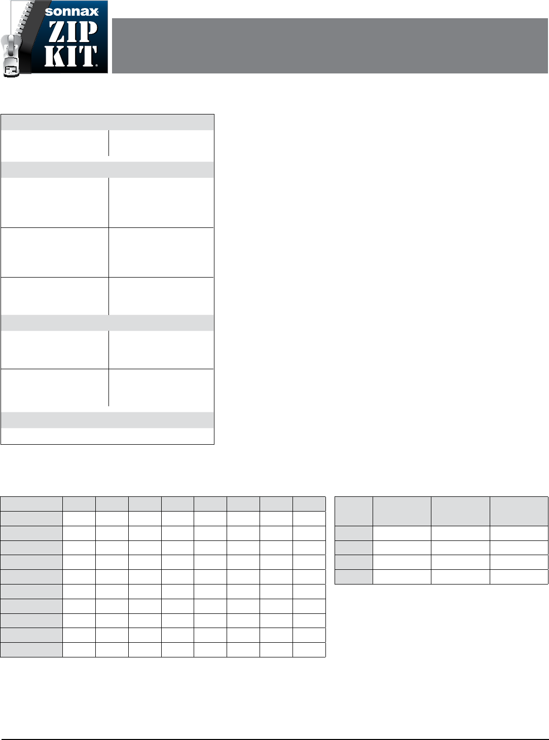
Torque Specifications
Pan Filter to Valve Body
96 in-lb
Oil Pan to Transaxle
72 in-lb
Component Pack Clearance
Forward (C1) Clutch
U140E/F: 4-Cyl .069–.082"
U140E/F: V6 .082–.095"
U240/241E: .056–.069"
Low & Reverse (B2) Brake
U140E/F: 4-Cyl .040–.048"
U140E/F: V6 .043–.051"
U240/241E: .043–.049"
2nd (B1) Brake
U140E/F: .024–.036"
U240E: .024–.029"
U241E: .024–.036"
Direct (C2) Input
U140E/F: .024–.033"
U240/241E: .024–.029"
Underdrive (C3) Clutch
U140E/F: .059–.075"
U240E/241E: .058–.067"
Underdrive (B3) Brake
U140E/F: .071–.087"
U240/241E: .074–.082"
End Play
Input Shaft
U140E/F: .010–.049"
U240E/241E: .011–.049"
Underdrive Unit
U140E/F: .020–.039"
U240E/241E: .008–.027"
Direct Clutch Assembly
U140E/F: .008–.037"
U240E/241E: .008–.035"
Fluid
Toyota Type T-IV
Electronic Cautions
Resetting Shift Adapts
e ECM (engine control module) has memorized values which must be relearned
after transmission repair. Use a scan tool (OE factory tool recommended) to reset
the ECM.
Post-Adapt Road Test
After resetting the ECM, a road test is required. Start the engine and warm it to
normal operating temperature. Perform a thorough road test with multiple accelera-
tions from a stop until proper shifting is obtained.
TSB TC002-06
Toyota published a Technical Service Bulletin regarding computer hardware prob-
lems in 2001-2003 RAV4 vehicles. Resetting the ECM will not eliminate shifting
complaints for this unit. A new ECM will be required.
Solenoids
Solenoids should be cleaned to remove debris that results in sticking and malfunction.
Toyota/Lexus U140E/F, U240E, U241E
Solenoid Function & Apply Chart
Gear
SL1 Controls
B1 Brake
SL2 Controls
C2 Clutch
S4 Controls
3-4 Shift
1st ON ON Off
2nd Off ON Off
3rd Off Off
4th Off ON
SLT: Controls line pressure.
DSL: Controls lockup clutch.
N-D ENGAGEMENT: 3rd gear is commanded during the
engagement, then 1st after the engagement is complete.
Toyota/Lexus U140E/F, U240E, U241E
Clutch Application Chart
Gear Range C1 C2 C3 B1 B2 B3 F1 F2
Park ON
Reverse ON ON ON
Neutral ON
D-1st Gear ON ON ON ON
D-2nd Gear ON ON ON ON
D-3rd Gear ON ON ON ON
D-Overdrive ON ON ON
2-1st Gear ON ON ON ON
2-2nd Gear ON ON ON ON ON
Low-1st Gear ON ON ON ON ON
TOYOTA U140E/F, U240E, U241E
ZIP KIT
PART NUMBER U140E-U241E-ZIP INSTALLATION & TESTING BOOKLET
©2016 Sonnax Industries, Inc. U140E-U241E-ZIP-Booklet_B 11-03-16
800-843-2600 • 802-463-9722 • F: 802-463-4059 • www.sonnax.com Page 1
U140E/F, U240E, U241E ZIP KIT Installation & Testing Booklet
11-03-16 U140E-U241E-ZIP-Booklet_B ©2016 Sonnax Industries, Inc.
Page 2 800-843-2600 • 802-463-9722 • F: 802-463-4059 • www.sonnax.com
TIME TESTED • INDUSTRY TRUSTED
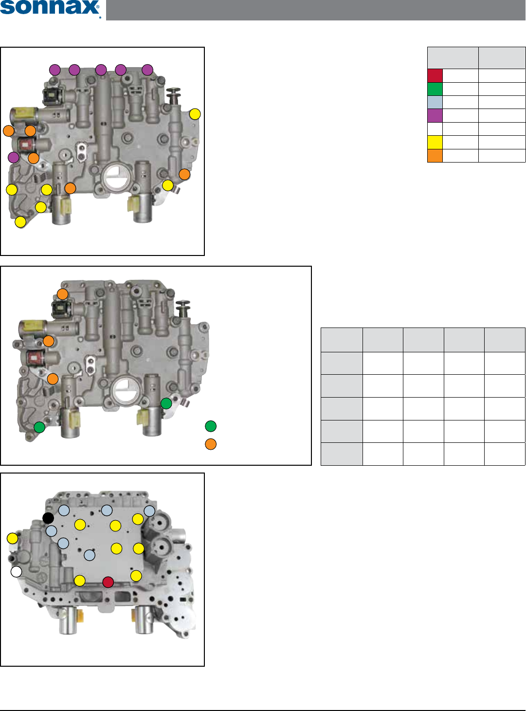
Zip Kit Instructions
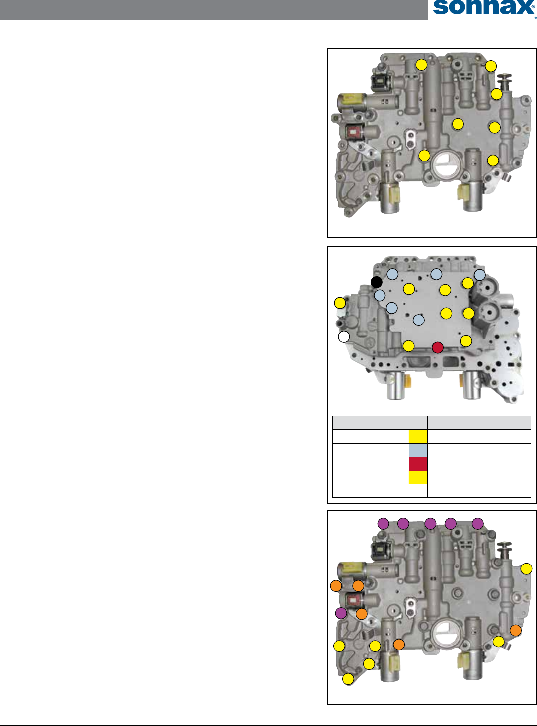
1. Valve Body Removal from Case
NOTE: See color chart for bolt lengths.
Remove the 17 bolts indicated (Figure 1).
2. Valve Body Disassembly: Step 1
NOTE: See Figure 2 and 3 for bolt locations.
e solenoids have diering resistance amounts (Figure
2). Ensure each of the solenoids are put back in their
correct location.
a. Remove the ve solenoids and bolts shown in Figure 2.
NOTE: Reference Figure 3 for steps b through e.
b. Remove the eight upper valve body bolts, #1 and #2.
c. Remove the seven upper valve body cover bolts, #3 and #4.
d. Remove bolt #5, bracket and checkball.
e. Remove checkball, location A.
Valve Body Removal from Case
Figure 1 Bolt Color
Code
Bolt
Length
Red 10mm
Green 12mm
Blue 14mm
Purple 25mm
White 30mm
Yellow 41mm
Orange 45mm
Solenoid U140E U140F U240E U241F
SL1 5.1–5.5
ohms
5.0–5.6
ohms
5.0–5.6
ohms
5.0–5.6
ohms
SL2 5.1–5.5
ohms
5.1–5.5
ohms
5.1–5.5
ohms
5.1–5.5
ohms
S4 11-15
ohms
11–15
ohms
11–15
ohms
11–15
ohms
DSL 11–15
ohms
11–13
ohms
11–13
ohms
11–13
ohms
SLT 5.0–5.6
ohms
5.1–5.5
ohms
5.1–5.5
ohms
5.1–5.5
ohms
Solenoid Resistance Chart
Figure 2
1
2
3
4
5
1. DSL Solenoid
2. SL2 Shift Solenoid
3. S4 Shift Solenoid
4. SLT Solenoid
5. SL1 Shift Solenoid
Solenoid Identication
= 58 in-lb.
= 97 in-lb.
Bolt Torque Specications
Solenoid Locations and Resistance
Valve Body Disassembly: Step 1
Figure 3
4
2
A
3
3
3
3
3
3
11
1 1
11
1
5
U140E/F, U240E, U241E ZIP KIT Installation & Testing Booklet
©2016 Sonnax Industries, Inc. U140E-U241E-ZIP-Booklet_B 11-03-16
800-843-2600 • 802-463-9722 • F: 802-463-4059 • www.sonnax.com Page 3
TIME TESTED • INDUSTRY TRUSTED
3. Valve Body Disassembly: Step 2
NOTE: See Figure 4 for bolt locations.
a. Remove the seven lower valve body bolts shown.
b. Hold separator plate against lower valve body. Lift o of upper valve body and
lay on bench with separator plate side up.
c. Remove separator plate from lower valve body. Note the location of all the
checkballs and retainers. Verication on page 8 in booklet.
4. Installation
Install Zip Kit parts as shown on diagram of separate quick guide sheet included in
this Zip Kit.
• When installing the lockup control plunger valve and sleeve kit in Step 2,
reuse the OE spring in between the new valve and sleeve if applicable.
• The Sonnax O-ringed end plugs in Step 3 must be installed with the O-ring
outboard.
5. Valve Body Assembly: Step 1
NOTE: See Figure 4 for bolt locations.
a. Loosely install the seven bolts.
b. Torque all bolts to 97 in-lb.
6. Valve Body Assembly: Step 2
NOTE: See Figure 5 for bolt locations and torque specications.
a. Reinstall checkball, location A.
b. Install checkball and bracket, then loosely install bolt #1.
c. Loosely install the seven upper valve body cover bolts, #2 and #3.
d. Loosely install the eight upper valve body bolts #4 and #5.
e. Torque all bolts in previous steps according to specs in Figure 5.
f. Install the ve solenoids and bolts shown in Figure 2 and torque
per spec indicated.
7. Valve Body Reinstallation to Case
NOTE: See Figure 6 for bolt locations.
a. Loosely install all 17 bolts. Reference bolt color and length chart on
previous page.
b. Torque all bolts to 8 ft-lb.
Valve Body Reinstallation to Case
Figure 6
Valve Body Disassembly: Step 2
and Valve Body Assembly: Step 1
Figure 4
Valve Body Assembly: Step 2
Figure 5
Bolt ID & Color Code Installation Torque Specs
Bolt #1 58 in-lb
Bolt #2 58 in-lb
Bolt #3 58 in-lb
Bolt #4 97 in-lb
Bolt #5 97 in-lb
3
5
A
2
2
2
2
2
2
44
4 4
44
4
1
U140E/F, U240E, U241E ZIP KIT Installation & Testing Booklet
11-03-16 U140E-U241E-ZIP-Booklet_B ©2016 Sonnax Industries, Inc.
Page 4 800-843-2600 • 802-463-9722 • F: 802-463-4059 • www.sonnax.com
TIME TESTED • INDUSTRY TRUSTED
*Part numbers with an asterisk (*) are included in this Zip Kit. Other part numbers are available separately.
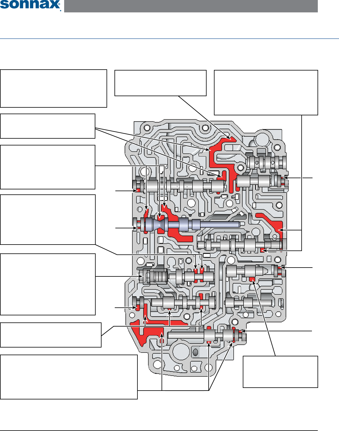
Critical Wear Areas & Vacuum Test Locations
NOTE: OE valves are shown in rest position and should be tested in rest position unless otherwise indicated. Test locations are pointed to with an arrow.
Springs are not shown for visual clarity. Low vacuum reading indicates wear and Sonnax parts noted for replacement.
Upper Valve Body – Bottom Side • U241E Shown Here
End Plugs, Multiple Locations
• Shift concerns • Clutch failure
Replace with Sonnax Part No.
57917E-20K
NOTE: Six Locations =
C2 (Direct) Exhaust Valve
• C2 Clutch burned
• Slipping/Flares in 3rd and 4th
Clutch Apply Control Plunger
Valve Assembly
• Clutch failure
• Burnt clutches
• Shift concerns
Replace with Sonnax Part No.
57917E-05K
Solenoid Modulator Valve
• Harsh/Flare upshifts
• TCC slip or cycling
• Low cooler ow
• Overheating
• Excessive Reverse pressure
• Bind-up
Replace with Sonnax Part No.
57917E-13K Requires F-57917E-TL13 & VB-FIX
Lockup Control Valve
• TCC apply & release concerns
• TCC codes • Burnt converter
Replace with Sonnax Part No.
27741-25K
Requires F-27741-TL25 & VB-FIX
NOTE: Test both ports at the same time.
B1 (2nd Gear Brake)
Control Valve
• B1 Brake clutches burned
• 2nd Quality poor
Lockup Relay Valve
• TCC apply & release concerns
• Overheating • TCC codes • Burnt converter
C2 (Direct) Lockup Valve
• C2 Clutch burned
• Slipping/Flares in 3rd and 4th
Lockup Control Plunger
Assembly
• Burnt converter • TCC codes
• TCC apply & release concerns
Replace with Sonnax Part No.
57917E-03K
NOTE: Vacuum testing of lockup control plunger
assembly not possible while in casting. Perform
visual inspection to identify wear.
Secondary Regulator Valve
• Harsh lockup • Burnt converter
• TCC apply & release concerns
Replace with Sonnax Part No.
57917E-16K
Requires F-57917E-TL16 & VB-FIX
U140E/F, U240E, U241E ZIP KIT Installation & Testing Booklet
©2016 Sonnax Industries, Inc. U140E-U241E-ZIP-Booklet_B 11-03-16
800-843-2600 • 802-463-9722 • F: 802-463-4059 • www.sonnax.com Page 5
TIME TESTED • INDUSTRY TRUSTED
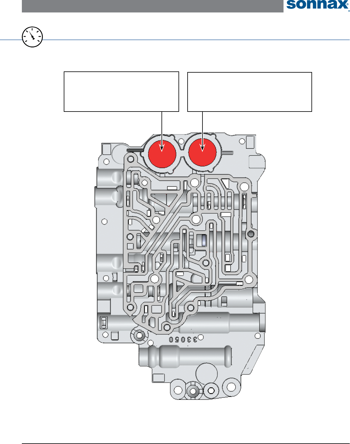
Items without part numbers are valid vacuum test locations for indicated drivability complaints, but do not have corresponding Sonnax parts due to low
percentage of bore wear.
Upper Valve Body – Top Side • U241E Shown Here
For specic vacuum test information, refer to individual part instructions included in kits and available at www.sonnax.com.
20
25
15
0
10
5
30
VACUUM
TEST
B1 (2nd Gear) Accumulator Piston
• B1 Brake clutches burned
• 1-2 Quality poor
Replace with Sonnax Part No.
57917E-19K
C2 (Direct) Accumulator Piston
• C2 Clutch Burned
• 2-3 Concerns
Replace with Sonnax Part No.
57917E-19K
U140E/F, U240E, U241E ZIP KIT Installation & Testing Booklet
11-03-16 U140E-U241E-ZIP-Booklet_B ©2016 Sonnax Industries, Inc.
Page 6 800-843-2600 • 802-463-9722 • F: 802-463-4059 • www.sonnax.com
TIME TESTED • INDUSTRY TRUSTED
*Part numbers with an asterisk (*) are included in this Zip Kit. Other part numbers are available separately.
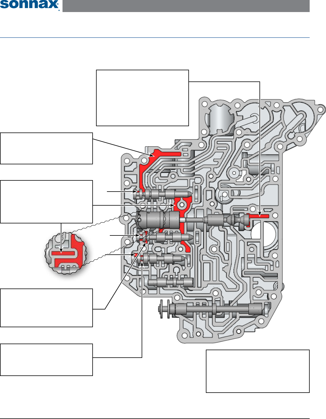
Critical Wear Areas & Vacuum Test Locations
NOTE: OE valves are shown in rest position and should be tested in rest position unless otherwise indicated. Test locations are pointed to with an arrow.
Springs are not shown for visual clarity. Low vacuum reading indicates wear and Sonnax parts noted for replacement.
Lower Valve Body – Bottom Side • U241E Shown Here
End Plugs, Multiple Locations
• Shift concerns
• Clutch failure
Replace with Sonnax Part No.
57917E-20K
NOTE: Three Locations =
Pressure Regulator Valve
• Low/High line pressure
• Soft/Harsh shifts
• Clutch and brake failure
• High line pressure in Reverse
• Low converter pressure
Replace with Sonnax Part No.
57917E-08K Requires 57917E-TL8
C2 (Direct Clutch)
Control Valve
• C2 Clutch burned
• Slipping/Flares in 3rd and 4th
Boost Valve Assembly
• High line pressure in Reverse
• Low line rise in Drive
• Soft shifts
Replace with Sonnax Part No.
57917E-01K
B1 (2nd Gear Brake)
Control Valve
• B1 Brake clutches burned
• 2nd Quality poor
B2 (1st and Reverse
Brake) Control Valve
• B2 Brake clutches burned
• Delayed Reverse
• Delayed engagement in manual low
U140E/F, U240E, U241E ZIP KIT Installation & Testing Booklet
©2016 Sonnax Industries, Inc. U140E-U241E-ZIP-Booklet_B 11-03-16
800-843-2600 • 802-463-9722 • F: 802-463-4059 • www.sonnax.com Page 7
TIME TESTED • INDUSTRY TRUSTED
111
101
Upper Valve Body
Top Side Shown
112
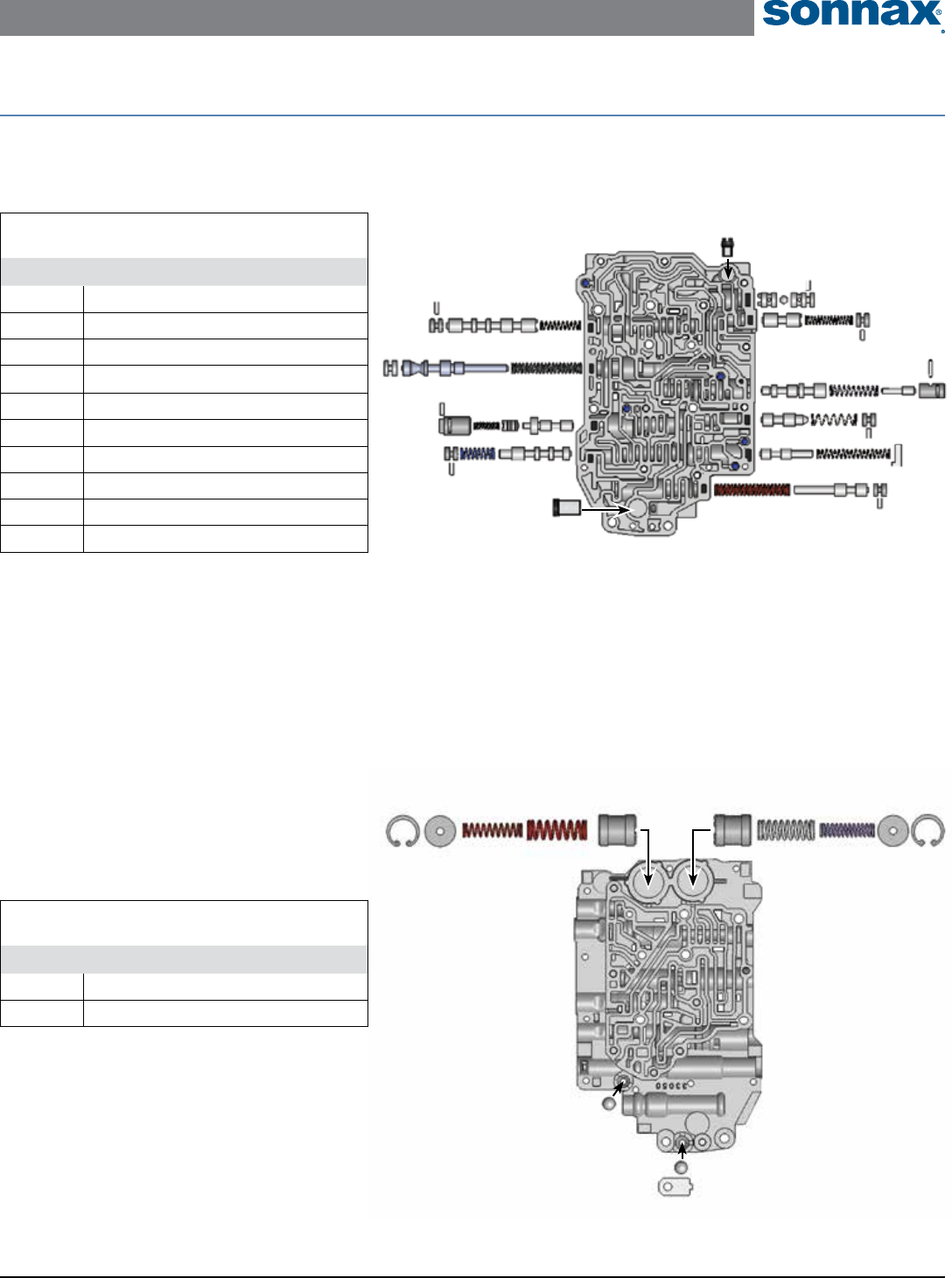
OE Exploded View
Upper & Lower Valve Body • U241E Shown Here
Upper Valve Body
Bottom Side Shown
110
109
108
107
106
101
102
103
105
104
Upper Valve Body Descriptions
I.D No. Description
101 C2 Lockup Valve
102 Secondary Regulator Valve
103 Lockup Control Valve
104 Lockup Relay Valve
105 Solenoid Modulator Valve
106 B3 Orice Control Valve
107 B1 Lockup Valve
108 Clutch Apply Control Valve
109 C2 Exhaust Valve
110 Three-Way Check Valve
Upper Valve Body Descriptions
I.D. No. Description
111 C2 Accumulator Piston
112 B1 Accumulator Piston
U140E/F, U240E, U241E ZIP KIT Installation & Testing Booklet
11-03-16 U140E-U241E-ZIP-Booklet_B ©2016 Sonnax Industries, Inc.
Page 8 800-843-2600 • 802-463-9722 • F: 802-463-4059 • www.sonnax.com
TIME TESTED • INDUSTRY TRUSTED
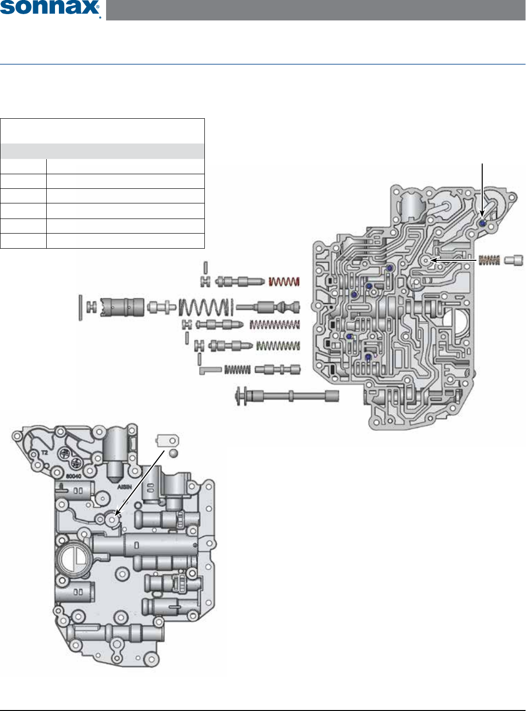
OE Exploded View
Upper & Lower Valve Body • U241E Shown Here
Lower Valve Body
Bottom Side Shown
206
201
202
203
205
204
Checkball is not used in all units.
Only use in models that have a
corresponding hole in the
separator plate at this location.
Lower Valve Body
Top Side Shown
Lower Valve Body Descriptions
I.D No. Description
201 C2 Control Valve
202 Main Regulator Valve
203 B2 Control Valve
204 B1 Control Valve
205 3-4 Shift Valve
206 Manual Valve
