U151E U250E ZIP IN B
2018-04-23
: Sonnax U151E-U250E-Zip-In B U151E-U250E-ZIP-IN_B 3048 instructions part uploads
Open the PDF directly: View PDF ![]() .
.
Page Count: 10
PART NUMBER U151E-U250E-ZIP QUICK GUIDE
installation Diagram
5
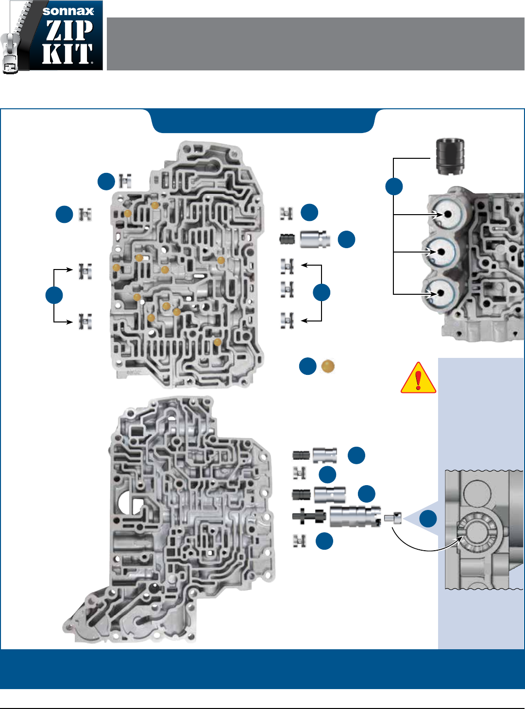
Install with open end out.
NOTE: Before
removing OE boost
sleeve, take note of
the adjustable step/
pin location and
ensure the Sonnax
sleeve is installed
at the same height/
location. Failure to
do so will result in
incorrect line pressure.
3
Cutaway shows a
side view of lower
valve body with
Sonnax boost valve
kit installed.
©2018 Sonnax Industries, Inc. U151E-U250E-ZIP-Guide_B 04-05-18
800-843-2600 • 802-463-9722 • F: 802-463-4059 • www.sonnax.com
TOYOTA/LEXUS U151E, U151F, U250E
Zip Kit®
Parts are labeled here in order of installation. See other side of sheet for details on Zip Kit contents.
In addition to general rebuilding tips and technical information, the technical booklet included in this kit contains vacuum
testing and additional repair options for higher mileage units or for repairing specic complaints which are beyond the
scope of this kit.
Upper Valve Body
7
Plastic Checkball
Shown in 11 places.
4
6
Medium
6
Small
6
Small
Large
6
Large
6
Lower Valve Body
1
2
6
Small
6
Small
TOYOTA/LEXUS U151E, U151F, U250E ZIP KIT® Quick Guide
Zip Kit Contents & Installation Steps
Step Replace OE B2 Plunger
Valve & Sleeve
Packaging Pocket 1
• Plunger Valve
• Plunger Sleeve
Step Replace OE B1 Plunger
Valve & Sleeve
Packaging Pocket 2
• Plunger Valve
• Plunger Sleeve
Step Replace OE Boost Valve,
Sleeve & Plug
NOTE: Ensure Sonnax sleeve is installed at the same
height/location as OE boost sleeve. Failure to do so will
result in incorrect line pressure.
Packaging Pocket 3
• Boost Valve
• Boost Sleeve
• Boost Valve Plug
Step
Replace OE Lockup Control
Plunger Valve & Sleeve
NOTE: Reuse OE spring if applicable.
Packaging Pocket 4
• Plunger Valve
• Plunger Sleeve
1
2
3
4
Step Replace OE Accumulator
Piston
NOTE: Use in the most worn location.
Place O-ring in deep groove, lubricate with Sonnax Slippery Stick™
O-LUBE and roll on bench to size.
Packaging Pocket 5
• Accumulator Piston
• O-Rings (2) 1 Extra
Step Replace OE End Plugs
Place O-ring in groove, lubricate with Sonnax Slippery Stick™ O-LUBE
and roll on bench to size. Install all end plugs with the O-ring outboard.
Packaging Pocket 6
• End Plugs, Large (5)
• O-Rings, Large (7) 2 Extra
Packaging Pocket 7
• End Plug, Medium
• O-Rings, Medium (2) 1 Extra
Packaging Pocket 8
• End Plugs, Small (4)
• O-Rings, Small (6) 2 Extra
Step Replace OE Checkballs
Packaging Pocket 9
Plastic Checkballs (11)
5
6
7
©2018 Sonnax Industries, Inc. U151E-U250E-ZIP-Guide_B 04-05-18
800-843-2600 • 802-463-9722 • F: 802-463-4059 • www.sonnax.com
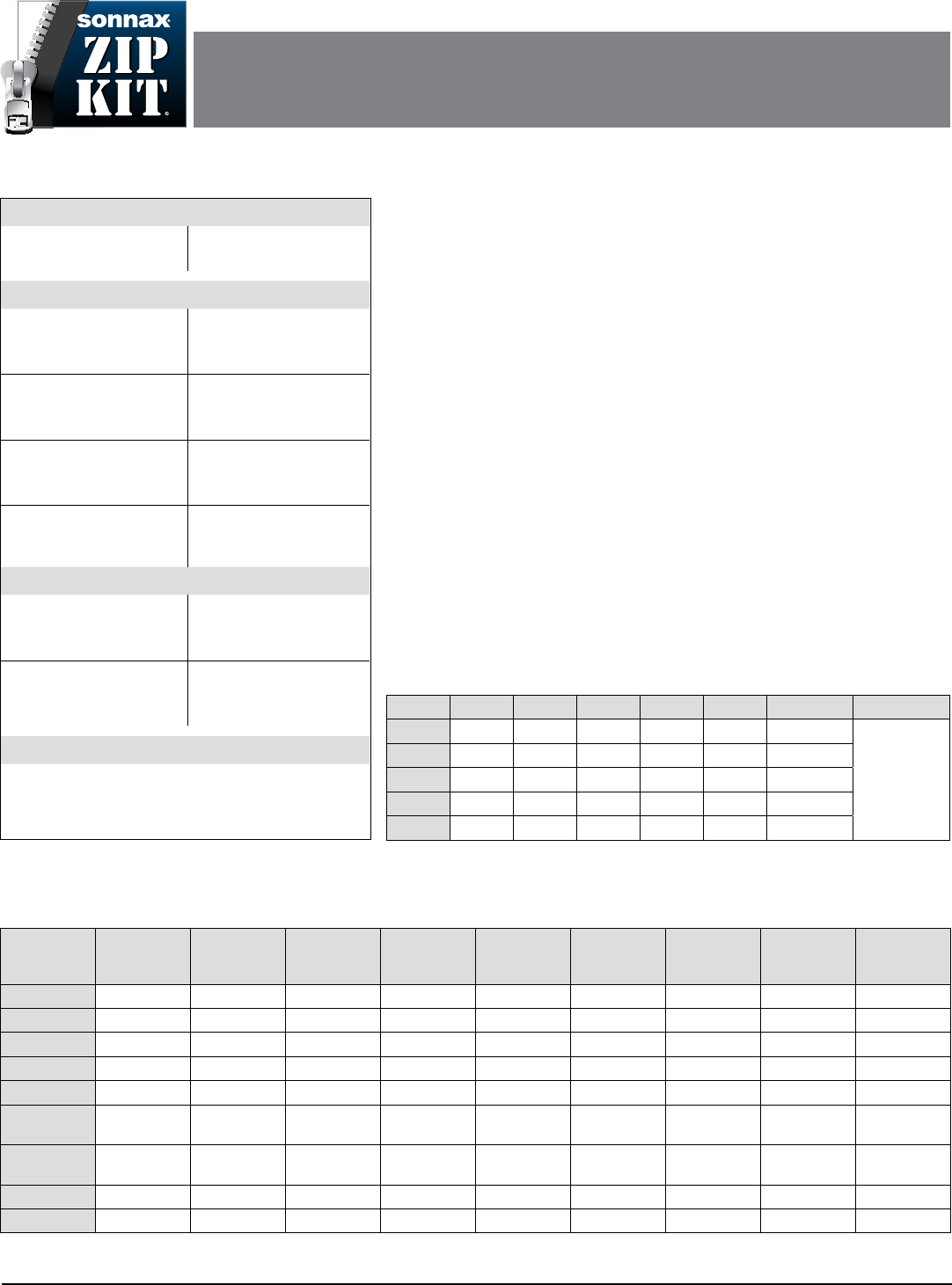
Torque Specifications
Pan Filter to Valve Body
8 ft-lb
Oil Pan to Transaxle
69 in-lb
Component Pack Clearance
Forward (C1) Clutch
U151E & U250E:
.039–.049"
Low & Reverse (B2) Brake
U151E: .046–.053"
U250E: .029–.048"
2nd (B1) Brake
U151E: .024–.036"
U250E: .021–.036"
Reverse (C2) Input
U151E & U250E:
.024–.032"
Direct (C0) Clutch
U151E: .024–.033"
U250E: .020–.033"
Underdrive (B3) Brake
U151E: .071–.087"
U250E: .065–.087"
Underdrive (C3) Clutch
U151E & U250E:
.059–.067"
End Play
Input Shaft
U151E & U250E:
.010–.049"
Underdrive Unit
U151E: .020–.040"
U250E: .008–.027"
Direct Clutch Assembly
U151E: .010–.036"
U250E: .008–.038"
Fluid
Toyota Genuine ATF WS PN: JWS3324 or NWS9638
Fluid level should be between the 2 hot marks on the stick:
• Dry Fill: 8.8 liters • Drain and Re-ll: 3.5 liters
Toyota/Lexus U151E/F, U250E Typical Solenoid Firing Order
Gear SL1 SL2 SL3 S4 SR DSL/TCC SLT
1st ON ON Off Off Off ON/M1
Modulates
based on
engine load.
2nd Off ON Off Off Off Off
3rd ON Off Off Off ON ON
4th Off Off ON Off ON ON
5th Off Off ON ON ON ON
Electronic Cautions
Resetting Shift Adapts
e ECM (engine control module) has memorized values which must be relearned
after transmission repair. Use a scan tool (OE factory tool recommended) to reset
the ECM.
Post-Adapt Road Test
After resetting the ECM, a road test is required. Start the engine and warm it to
normal operating temperature. Perform a thorough road test with multiple accelera-
tions from a stop until proper shifting is obtained.
Solenoids
Solenoids should be cleaned to remove debris that results in sticking and malfunction.
Gear Range
Forward
Clutch C1
Reverse
Input
Clutch C2
Direct
Clutch C0
Underdrive
Clutch C3
2nd Brake
B1
Low &
Reverse
Brake B2
Underdrive
Brake B3
No. 1
One Way
Clutch F1
No. 2
One Way
Clutch F2
Park ON
Reverse ON ON ON
Neutral ON
D-1st Gear ON ON ON ON
D-2nd Gear ON ON ON ON
D-3rd Gear
High Ratio ON ON ON
D-3rd Gear
Low Ratio ON ON ON ON
D-4th Gear ON ON ON ON
D-5th Gear ON ON ON
Toyota/Lexus U151E/F, U250E Component Application Chart
TOYOTA/LEXUS U151E, U151F, U250E
Zip Kit®
PART NUMBER U151E-U250E-ZIP INSTALLATION & TESTING BOOKLET
©2018 Sonnax Industries, Inc. U151E-U250E-ZIP-Booklet_B 04-05-18
800-843-2600 • 802-463-9722 • F: 802-463-4059 • www.sonnax.com Page 1
TOYOTA/LEXUS U151E, U151F, U250E ZIP KIT®
Installation & Testing Booklet
04-05-18 U151E-U250E-ZIP-Booklet_B ©2018 Sonnax Industries, Inc.
Page 2 800-843-2600 • 802-463-9722 • F: 802-463-4059 • www.sonnax.com
TIME TESTED • INDUSTRY TRUSTED
Zip Kit Instructions
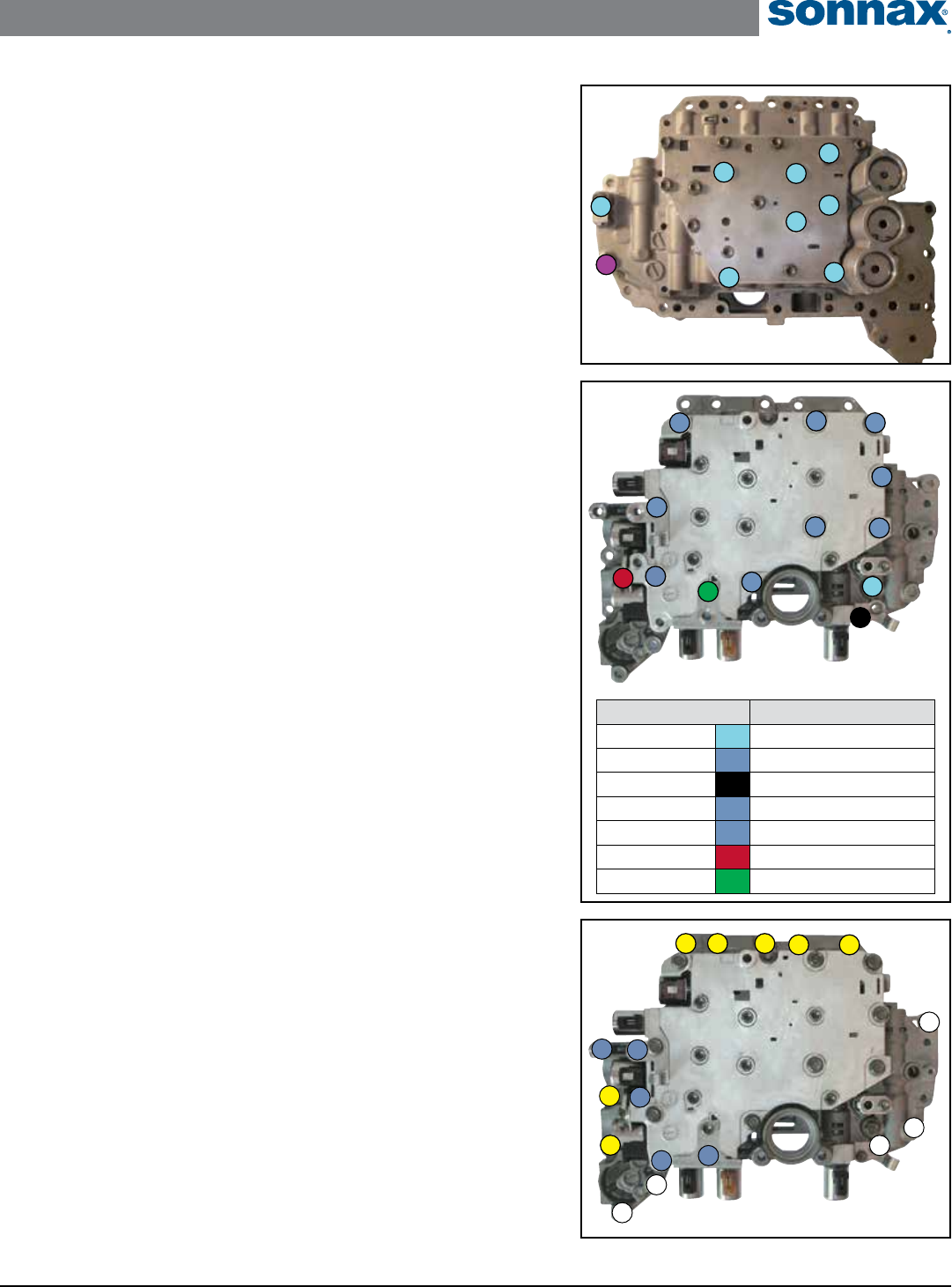
1. Valve Body Removal from Case
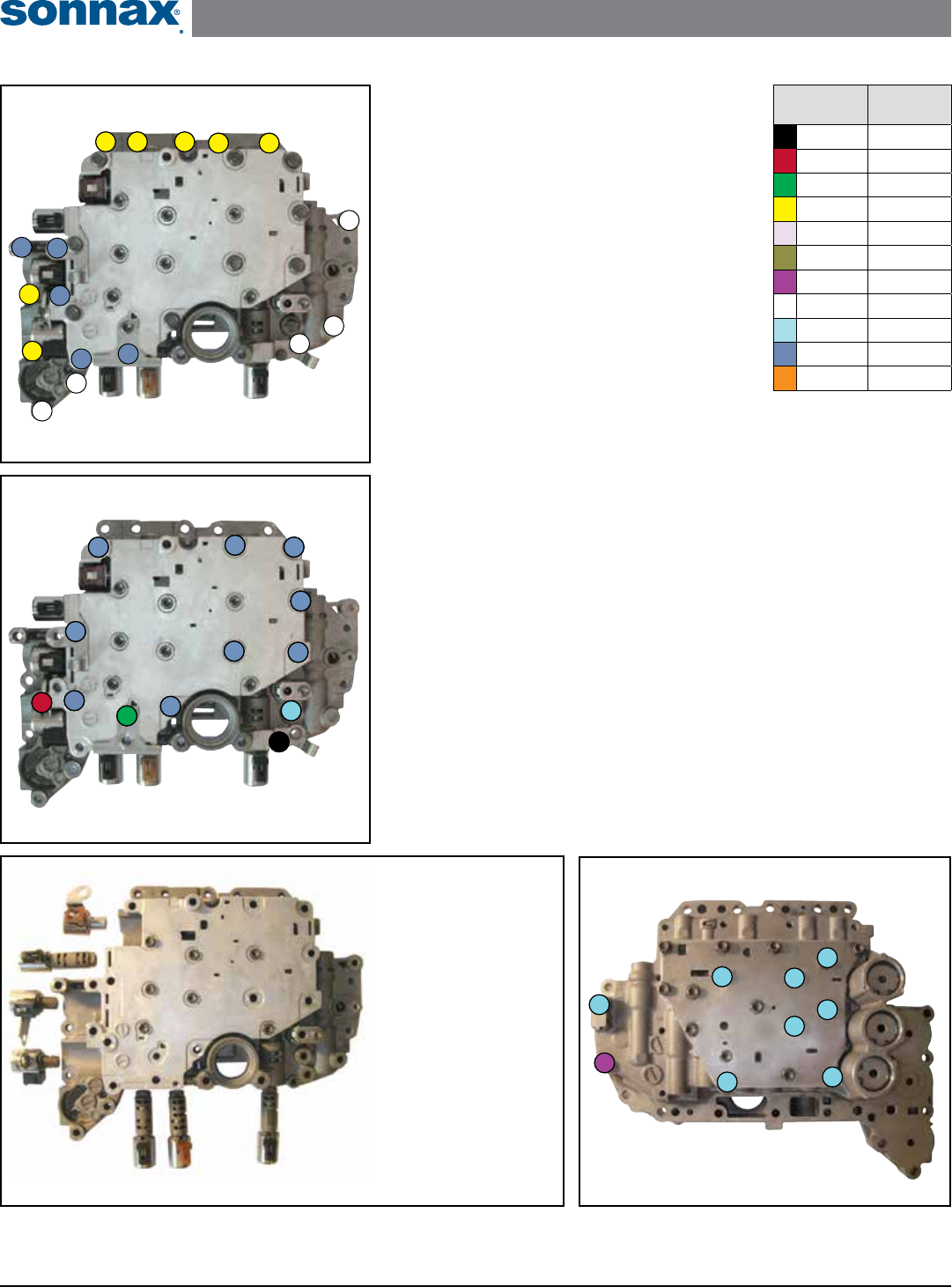
Remove the 19 bolts indicated (Figure 1).
2. Valve Body Disassembly: Step 1
NOTE: See Figure 2 for bolt locations.
Solenoids can be put into the wrong location in the
valve body. Ensure each of them are put back in their
correct location. Solenoid designs have changed over the
years, see Figure 3 for the most common conguration.
a. Remove bolt #1 and locking plate. Remove shift
solenoid SL3 and the SLT solenoid.
b. Remove bolt #2 and shift solenoid S4, then SR
solenoid.
c. Remove bolt #3 and shift solenoid DSL.
d. Remove bolt #4 and locking plate. Remove shift solenoid SL2.
e. Remove bolt #5 and locking plate. Remove shift solenoid SL1.
f. Remove the seven #6 bolts.
g. Remove the #7 bolt.
3. Valve Body Disassembly: Step 2
NOTE: See Figure 4 for bolt locations.
a. Remove the light blue #1 bolt, retaining bracket and checkball.
b. Remove the seven remaining light blue bolts.
c. Remove the purple bolt.
1
Valve Body Disassembly: Step 2
Figure 4
Valve Body Removal from Case
1. DSL (TCC) Solenoid,
11–15 Ohms
2. SL2 Solenoid,
4.5–6.0 Ohms
3. S4 Solenoid,
11–15 Ohms
4. SR Solenoid,
11–15 Ohms
5. SL3 Solenoid,
4.5–6.0 Ohms
6. SLT Solenoid,
4.5–6.0 Ohms
7. SL1 Solenoid,
4.5–6.0 Ohms
Figure 3
1
2
3
4
5 6
7
Solenoid Locations and Resistance
Bolt
Color Code
Bolt
Length
Black 12mm
Red 16.75mm
Green 21.50mm
Yellow 25.00mm
Lt Purple 26.50mm
Olive 30mm
Purple 35.50mm
White 41.00mm
Lt Blue 46.50mm
Blue 57.00mm
Orange 62.50mm
Figure 1
Valve Body Disassembly: Step 1
Figure 2
1
5
3
4
2
6
6
6
6
6
7
6
6
1
5
3
4
2
6
6
6
6
6
7
6
6
TOYOTA/LEXUS U151E, U151F, U250E ZIP KIT®
Installation & Testing Booklet
©2018 Sonnax Industries, Inc. U151E-U250E-ZIP-Booklet_B 04-05-18
800-843-2600 • 802-463-9722 • F: 802-463-4059 • www.sonnax.com Page 3
TIME TESTED • INDUSTRY TRUSTED
4. Installation
Install Zip Kit parts as shown on diagram of separate quick guide sheet included in
this Zip Kit.
• When installing the lockup control plunger valve and sleeve kit in Step 4,
reuse the OE spring between the new valve and sleeve.
• The Sonnax O-ringed end plugs in Step 6 must be installed with the O-ring
outboard.
5. Valve Body Assembly: Step 1
NOTE: See Figure 5 for bolt locations.
a. Loosely install the purple bolt.
b. Loosely install the seven, unnumbered light blue bolts.
c. Loosely install the light blue #8 bolt, retaining bracket and checkball.
d. Torque all bolts to 90 in-lb.
6. Valve Body Assembly: Step 2
NOTE: See Figure 6 for bolt locations and torque specications.
a. Loosely install bolt #1.
b. Loosely install the seven #2 bolts.
c. Install shift solenoid SL1 and locking plate. Loosely install bolt #3.
d. Install shift solenoid SL2 and locking plate. Loosely install bolt #4.
e. Install shift solenoid DSL. Loosely install bolt #5.
f. Install the SR solenoid, then shift solenoid S4. Loosely install bolt #6.
g. Install shift solenoid SL3 and the SLT solenoid. Install the locking plate and
loosely install bolt #7.
h. Torque all bolts as indicated in chart (Figure 6).
7. Valve Body Reinstallation to Case
NOTE: See Figure 7 for bolt locations.
a. Loosely install all 19 bolts. Reference the color chart on previous page for bolt
lengths.
b. First tighten the two #1 positioning bolts to 8 ft-lb. Torque the remaining
bolts to the same 8 ft-lb.
8
Valve Body Assembly: Step 1
Figure 5
Figure 7
1
Valve Body Reinstallation to Case
1
Valve Body Assembly: Step 2
Figure 6
Bolt ID & Color Code Installation Torque Specs
Bolt #1 90 in-lb
Bolt #2 90 in-lb
Bolt #3 58 in-lb
Bolt #4 8 ft-lb
Bolt #5 8 ft-lb
Bolt #6 8 ft-lb
Bolt #7 58 in-lb
7
3
5
4
6
2
2
2
2
2
1
2
2
TOYOTA/LEXUS U151E, U151F, U250E ZIP KIT®
Installation & Testing Booklet
04-05-18 U151E-U250E-ZIP-Booklet_B ©2018 Sonnax Industries, Inc.
Page 4 800-843-2600 • 802-463-9722 • F: 802-463-4059 • www.sonnax.com
TIME TESTED • INDUSTRY TRUSTED
*Part numbers with an asterisk (*) are included in this Zip Kit. Other part numbers are available separately.
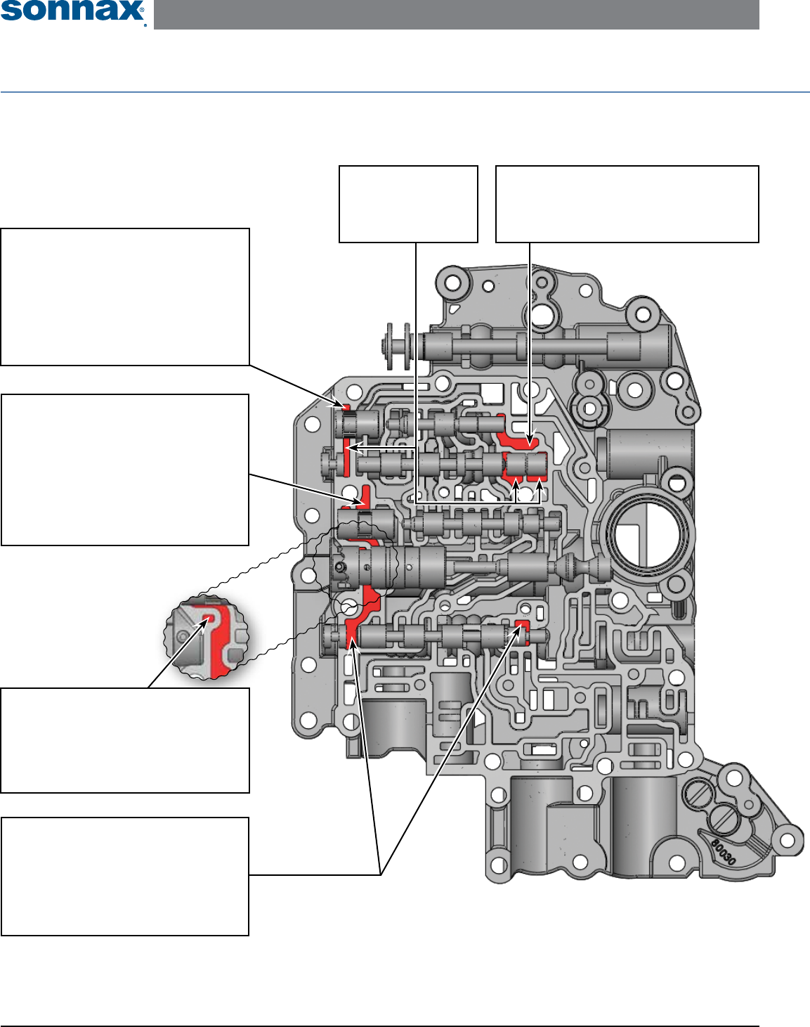
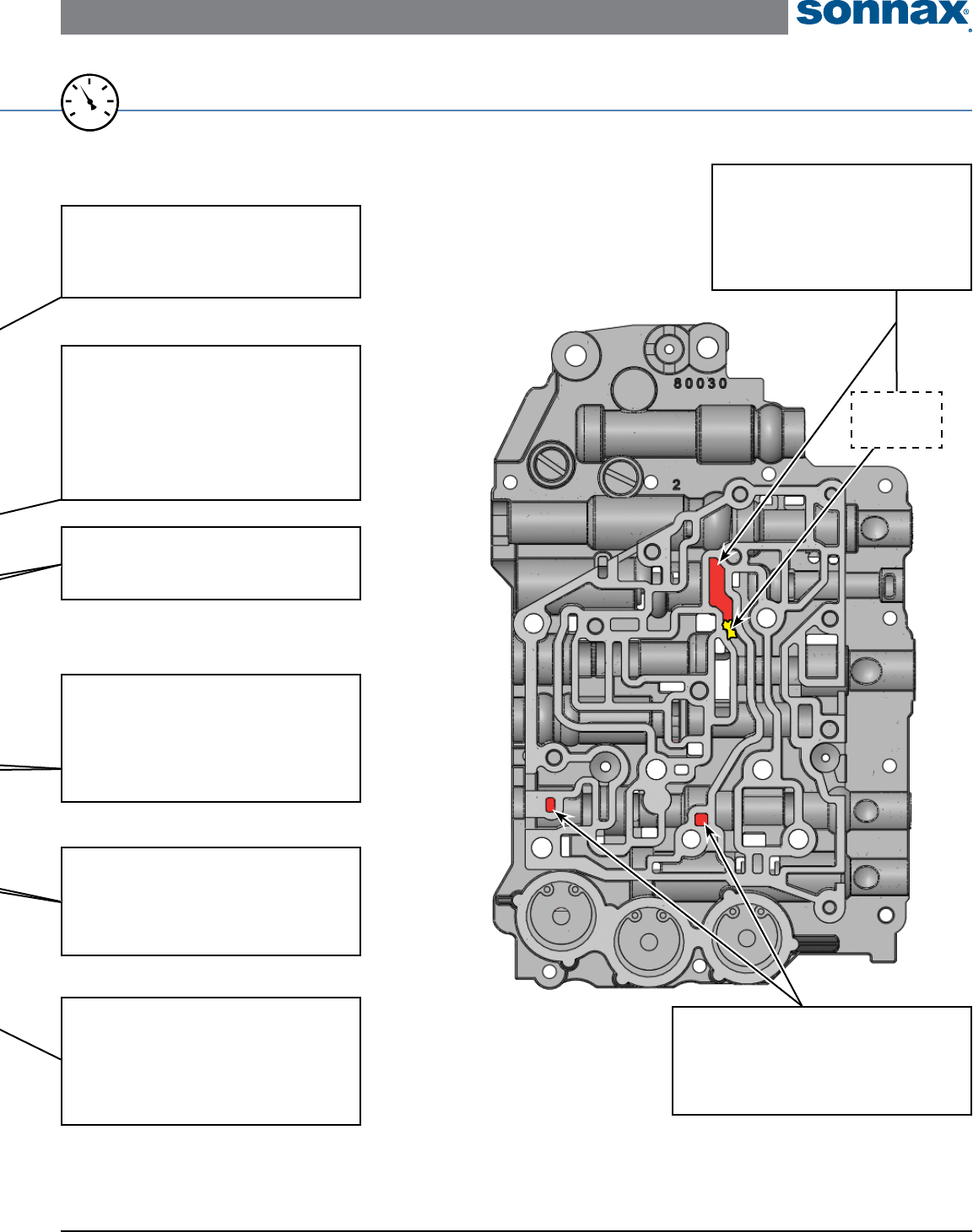
Critical Wear Areas & Vacuum Test Locations
NOTE: OE valves are shown in rest position and should be tested in rest position unless otherwise indicated. Test locations are pointed to with an arrow.
Springs are not shown for visual clarity. Low vacuum reading indicates wear and Sonnax parts noted for replacement.
Lower Valve Body – Bottom Side • U250E Shown Here
Clutch Apply Control Valve
• Burnt Forward/C1 Clutch, Direct/C0 Clutch
and 2nd/B1 Brake
• Flare shifts • Bind-ups
Replace with Sonnax Part No.
27741-18K Requires F-27741-TL18 & VB-FIX
NOTE: Stroke valve to ensure it is not stuck.
B2 (Low/Reverse) Apply
Control Plunger
• Delayed Reverse
• B2 Brake clutches burned
• No engine braking in manual low
• Erratic shift timing
Replace with Sonnax Part No.
27741-06K*
B1 (2nd) Apply
Control Plunger
• 2-3 or 4-3 Bind-up
• B1 brake clutches burned
• Harsh 1 through 4 maneuver shifts
• Erratic shift timing
Replace with Sonnax Part No.
27741-04K*
NOTE: Seal port on opposite side when testing.
Boost Valve
• Soft shifts
• Low line rise in Drive
• High line pressure in Reverse
Replace with Sonnax Part No.
27741-01K*
B2 (Low/Reverse) Switch Valve
• B2 Brake clutches burned
• Delayed Reverse
• No engine braking in manual low
4-5 Shift Valve
• Delayed 3rd
• UD/C3 Clutch burned
• Delayed/No 5th
TOYOTA/LEXUS U151E, U151F, U250E ZIP KIT®
Installation & Testing Booklet
©2018 Sonnax Industries, Inc. U151E-U250E-ZIP-Booklet_B 04-05-18
800-843-2600 • 802-463-9722 • F: 802-463-4059 • www.sonnax.com Page 5
TIME TESTED • INDUSTRY TRUSTED
Items without part numbers are valid vacuum test locations for indicated drivability complaints, but do not have corresponding Sonnax parts due to low
percentage of bore wear.
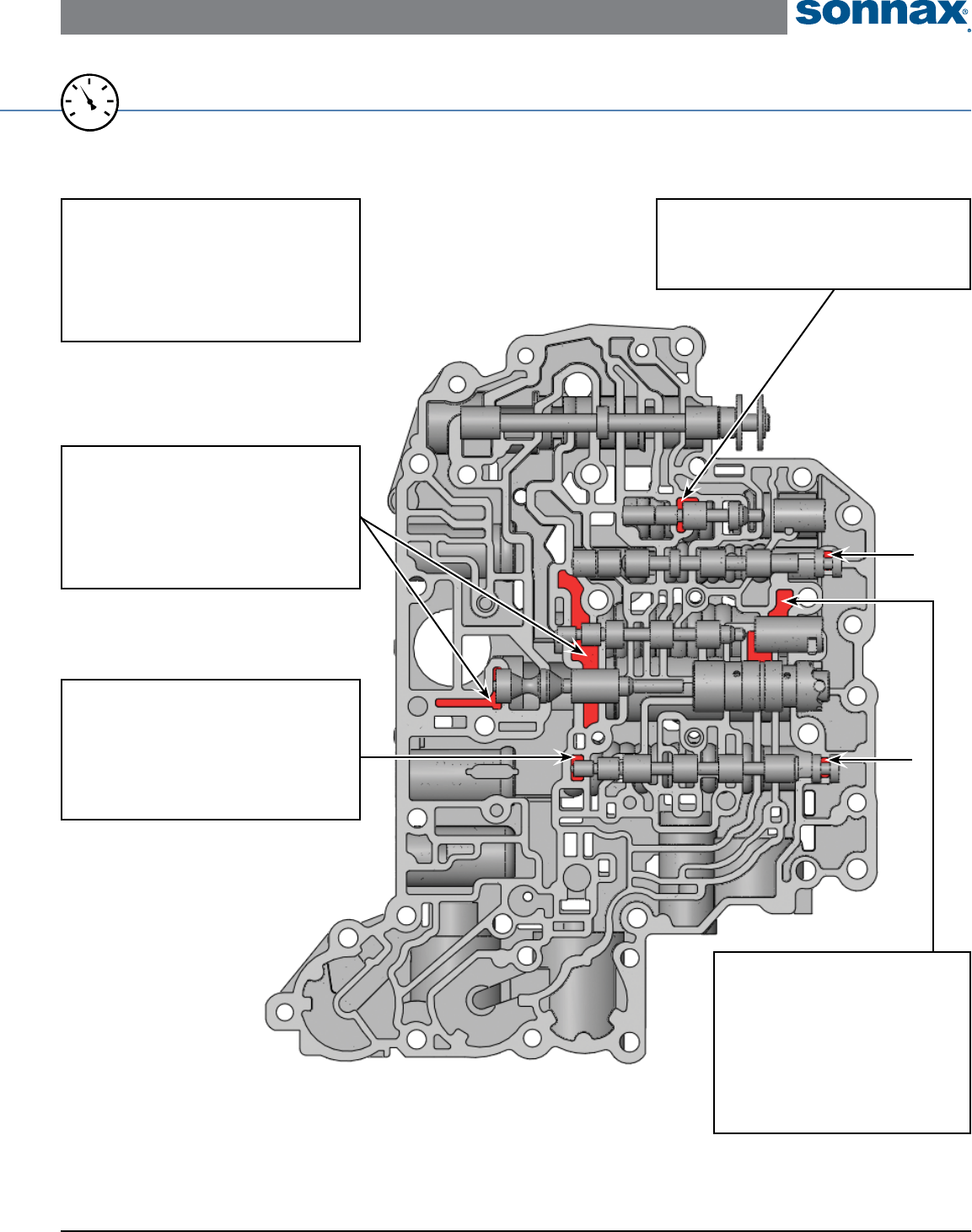
Lower Valve Body – Top Side • U250E Shown Here
For specic vacuum test information, refer to individual part instructions included in kits and available at www.sonnax.com.
20
25
15
0
10
5
30
VACUUM
TEST
B1 (2nd) Apply
Control Plunger
• 2-3 or 4-3 Bind-up
• B1 brake clutches burned
• Harsh 1 through 4 maneuver shifts
• Erratic shift timing
Replace with Sonnax Part No.
27741-04K*
NOTE: Seal this port and test on opposite side.
Clutch Apply Control Valve
• Burnt Forward/C1 Clutch, Direct/C0 Clutch
& 2nd/B1 Brake
• Flare shifts • Bind-ups
Replace with Sonnax Part No.
27741-18K Requires F-27741-TL18 & VB-FIX
NOTE: Stroke valve to ensure it is not stuck.
Pressure Regulator Valve
• Soft shifts • Low line pressure • Harsh shifts
• High line pressure in Reverse
• Clutch & band failures
• Low converter pressure • High line pressure
Replace with Sonnax Part No.
27741-08K Requires 57917E-TL8
End Plugs, Multiple Locations
• Inconsistent shift quality • Flare shifts
• Clutch failure • Bump shifts • Bang shifts
• Shift codes
Replace with Sonnax Part No.
27741-20K*
NOTE: Two Locations =
B2 (Low/Reverse) Switch Valve
• B2 Brake clutches burned
• Delayed Reverse
• No engine braking in manual low
TOYOTA/LEXUS U151E, U151F, U250E ZIP KIT®
Installation & Testing Booklet
04-05-18 U151E-U250E-ZIP-Booklet_B ©2018 Sonnax Industries, Inc.
Page 6 800-843-2600 • 802-463-9722 • F: 802-463-4059 • www.sonnax.com
TIME TESTED • INDUSTRY TRUSTED
*Part numbers with an asterisk (*) are included in this Zip Kit. Other part numbers are available separately.
†One accumulator piston kit included in Zip Kit, choose most worn location.
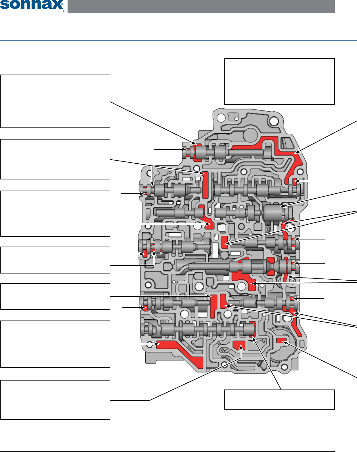
Critical Wear Areas & Vacuum Test Locations
NOTE: OE valves are shown in rest position and should be tested in rest position unless otherwise indicated. Test locations are pointed to with an arrow.
Springs are not shown for visual clarity. Low vacuum reading indicates wear and Sonnax parts noted for replacement.
Upper Valve Body – Bottom Side • U250E Shown Here End Plugs, Multiple Locations
• Shift concerns
• Clutch failure
Replace with Sonnax Part No.
27741-20K*
NOTE: Eight locations =
Solenoid Modulator Valve
• Slips & ares • Erratic shift feel & engagements
• Harsh upshifts • Bind-up • Low cooler ow
• Excess Reverse pressure & distorted housings
• TCC cycling/slip • Overheating
Replace with Sonnax Part No.
27741-13K Requires F-27741-TL13 & VB-FIX
B3 Orice Control Valve
• Shift concerns
• UD/B3 Brake clutches burned
Replace with Sonnax Part No.
27741-16K Requires F-15741-TL18 & VB-FIX
NOTE: Stroke valve to ensure it is not stuck.
B1 (2nd) Accumulator Piston
• Delayed engagement • Flare shifts
• Forward slip • Burnt clutches
Replace with Sonnax Part No.
57917E-19K*†
B2 (Low/Reverse)
Control Valve
• B2 Brake clutches burned
• Delayed Reverse
• Delayed engagement in manual 1st
Accumulator Control Valve
• Shift concerns
• Burnt clutches & brakes
C0 (Direct)
Accumulator Piston
• Delayed engagement • Flare shifts
• Forward slip • Burnt clutches
Replace with Sonnax Part No.
57917E-19K*†
C0 (Direct) Control Valve
• C0 Clutch burned
• Slipping/Flares in 3rd, 4th & 5th
Solenoid Relay Valve
• Shift concerns
TOYOTA/LEXUS U151E, U151F, U250E ZIP KIT®
Installation & Testing Booklet
©2018 Sonnax Industries, Inc. U151E-U250E-ZIP-Booklet_B 04-05-18
800-843-2600 • 802-463-9722 • F: 802-463-4059 • www.sonnax.com Page 7
TIME TESTED • INDUSTRY TRUSTED
Upper Valve Body – Top Side • U250E Shown Here
For specic vacuum test information, refer to individual part instructions included in kits and available at www.sonnax.com.
20
25
15
0
10
5
30
VACUUM
TEST
Secondary Pressure
Regulator Valve
• TCC apply & release concerns • TCC codes
• Burnt converter • Lube failures
Replace with Sonnax Part No.
57917E-16K Requires F-57917E-TL16 & VB-FIX
Items without part numbers are valid vacuum test locations for indicated drivability complaints, but do not have corresponding Sonnax parts due to low
percentage of bore wear.
B1 (2nd) Control Valve
• B1 Brake clutches burned
• Slipping/Flares in 2nd, 4th & 5th
C1 (Forward) Control Valve
• C1 Clutch burned
• Delayed engagement
• Slipping/Flares in 1st, 2nd & 3rd
NOTE: Seal these ports and test on opposite side.
C1 (Forward)
Accumulator Piston
• Delayed engagement • Flare shifts
• Forward slip • Burnt clutches
Replace with Sonnax Part No.
57917E-19K*†
Lockup Relay Valve
• TCC apply & release concerns
• TCC codes
• Burnt converter/overheating
Lockup Control
Plunger Assembly
• TCC apply & release concerns
• TCC codes • Burnt converter
Replace with Sonnax Part No.
57917E-03K
NOTE: Vacuum testing of lockup control plunger assembly not possible
while in casting. Perform visual inspection to identify wear.
C1 (Forward) Control Valve
• C1 Clutch burned
• Delayed engagement
• Slipping/Flares in 1st, 2nd & 3rd
NOTE: Seal ports on opposite side when testing.
Lockup Control Valve
• TCC apply & release concerns
• TCC codes
• Burnt converter
Replace with Sonnax Part No.
27741-25K RequiRes F-27741-TL25 & VB-FiX
NOTE: Place
clay here to
isolate circuit.
TOYOTA/LEXUS U151E, U151F, U250E ZIP KIT®
Installation & Testing Booklet
04-05-18 U151E-U250E-ZIP-Booklet_B ©2018 Sonnax Industries, Inc.
Page 8 800-843-2600 • 802-463-9722 • F: 802-463-4059 • www.sonnax.com
TIME TESTED • INDUSTRY TRUSTED
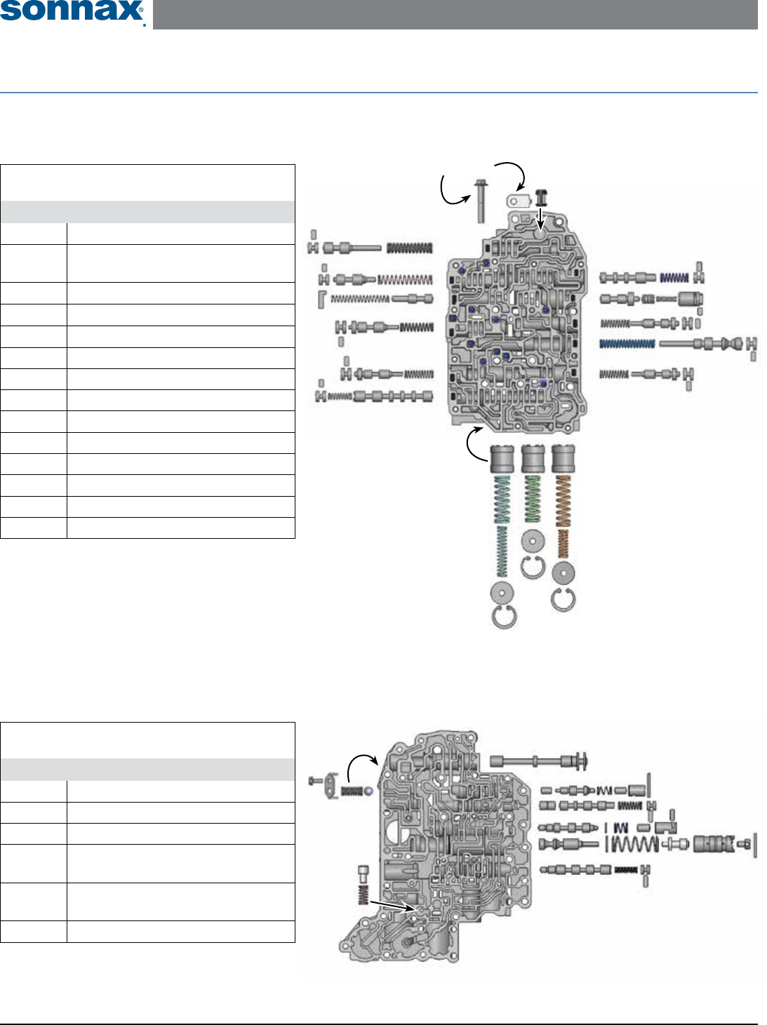
Upper Valve Body Descriptions
I.D No. Description
201 Lockup Relay Valve
202 Lockup Control Valve & Plunger
Valve Assembly
203 B1 Control Valve
204 Secondary Regulator Valve
205 C1 Control Valve
206 Solenoid Relay Valve
207 C0 Control Valve
208 Accumulator Control Valve
209 B3 Orice Control Valve
210 B2 Control Valve
211 Solenoid Modulator Valve
212 C0 Accumulator Piston
213 B1 Accumulator Piston
214 C1 Accumulator Piston
Lower Valve Body Descriptions
I.D. No. Description
101 Manual Valve
102 B2 Switch Valve & Plunger Valve
103 4-5 Shift Valve
104 B1 Switch Valve & Plunger
Valve Assembly
105 Main Pressure Regulator Valve
& Boost Valve Assembly
106 Clutch Apply Control Valve
OE Exploded View
Upper & Lower Valve Body • U250E Shown Here
211
Upper Valve Body
Bottom Side Shown
210
209
208
207
206
201
202
203
205
204
214
101
102
106
105
104
103
Accumulator Pistons
Installed on Top Side
Installed on Top Side
Lower Valve Body
Top Side Shown
Installed on
Bottom Side
212
213
