Sonova USA WALLP Phonak WallPilot User Manual WallPilot User Guide
Phonak Inc Phonak WallPilot WallPilot User Guide
Manual

GA 029-0171-02 GB Englisch
hearing systems
WallPilotTM
User Guide
Contents
Page
Description
Welcome to the world of multi-frequency FM communication
Main components 3
Installation
Choosing the right location 4
Preparing for installation 6
Mounting to the wall 8
Battery replacement 9
Selecting the channel 10
Adjusting the range 11
Key lock 12
Daily use 13
Important notes 15
Phonak distributors worldwide
Service and Warranty
GA 029-0171-02 GB Englisch
Description
3
6
7
1
10 4
2
8
9
5
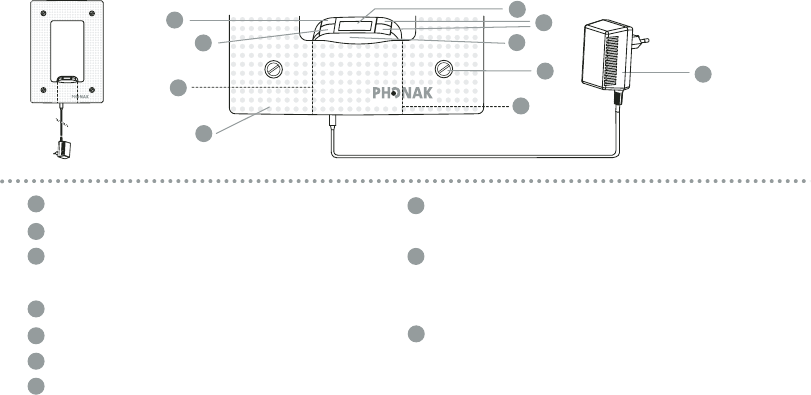
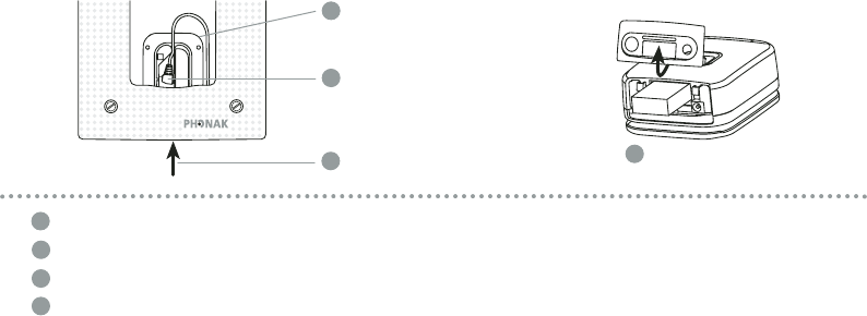
Main unit
Frame with built-in antenna
Antenna cable connection to main unit
(not visible on this diagram)
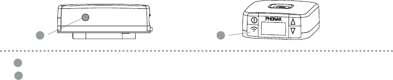
Power cord
On/Off switch
Channel selector (up/down)
LCD display
7
6
5
4
3
2
1
3-position coarse range adjustment
(F1/F2/F3)
Rotary control for continuous fine
range adjustment
(not visible on this diagram)
Fixation screws
10
9
8

Welcome to the world of multi-frequency FM
communication
Thank you for choosing the WallPilot, a fully automatic, wireless frequency
synchronizer especially developed for use with multi-frequency MicroLink receivers.
The WallPilot ensures that FM users entering a room are automatically switched to
the right channel. The process is fully automatic and completely independent of the
channel previously in use by the FM receiver. The WallPilot is ideal for schools and
other buildings where FM is used in several rooms at once.
The WallPilot is a Swiss quality product that will give many years of excellent service.
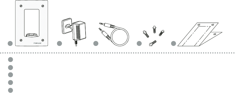
Main components
3
GA 029-0171-02 GB Englisch
WallPilot with integral main unit
Power cord
Audio cable for optional software programming of the main unit
Fixation screws and screw anchors for wall mounting
Hole drilling template for wall mounting
5
4
3
2
1
121 513 4
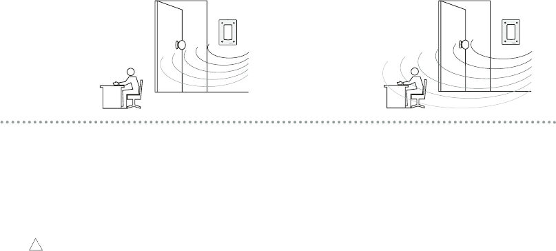
Choosing the right location
4
The choice of location depends on local conditions. Please consider the following:
• The WallPilot range is continuously adjustable from zero to two meters.
• The WallPilot synchronization signal reaches any FM receiver within the set range.
For this reason, FM users who are already in the room should not remain perma-
nently within the reception range of the WallPilot signal (see figure).
The WallPilot transmits its synchronization signal equally in all directions (360°).
The signal can pass through walls, meaning it may also be picked up by an FM
receiver outside the room.
Within
WallPilot range
Outside of
WallPilot
range Correct Incorrect
!
GA 029-0171-02 GB Englisch
5
The WallPilot is designed for mounting to a wall. Possible locations for the unit are:
•Inside the room, adjacent to the entrance door
The WallPilot then covers the room entry zone, which is the ideal location if there is
sufficient space. However, classroom desks and other working areas must be out of
range of the WallPilot.
•In a vacant area within the room
The floor can be marked to show where people should walk past in order to receive
the WallPilot synchronization signal. This option allows reduction of the operating
range to a minimum.
•In an entry corridor
This is the recommended position when the room is at the end of a corridor, and FM
users pass through the corridor solely for classroom access.
6
Preparing for installation
• Determine the approximate location according to the previous criteria.
• Put the WallPilot into operation (see next section) and either hold it against the wall
or rest it on a chair (standing up, not lying flat).
• Turn the range adjustment control (see page 11) fully clockwise (max.) and set the
range switch to ‘F1’ (short range).
• Do practical tests with hearing instruments and FM receivers.
• If the range is too great:
Decrease the range as necessary using the rotary control (turn counter-clockwise)
GA 029-0171-02 GB Englisch
7
• If the range is too small:
Set the range switch to ‘F2’ (medium range) and again turn the rotary range control
fully clockwise.
• Keep testing until the optimum range is adjusted. Once the range is optimized, test
to ensure that the WallPilot signal does not reach FM users at undesired locations
(e.g. in the corridor outside, sitting at desks, en route to the blackboard, etc.). In
case of problems, select a different location for the WallPilot. An alternative is to
restrict the range as necessary; in this case we recommend marking the floor to
indicate the WallPilot reception area.
• After finding a good location in this way, proceed to mounting the WallPilot to
the wall.
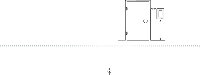
Mounting to the wall
~5 cm (feet)
~1.1 m (feet)
• Drill fixation holes using the supplied template as a guide
• Insert the screw anchors
• Secure the WallPilot to the wall using the supplied fixation screws
• Plug the power cord into the socket marked on the main unit.
The WallPilot can operate directly using the power cord, or on rechargeable batteries
(for approx. 12 hours)
☞Mains power is recommended for ease of use. 8
GA 029-0171-02 GB Englisch
Battery replacement
9
Push up to open lid
Remove main unit
Remove antenna cable
The WallPilot main unit includes a removable rechargeable battery. The battery and
power cord are the same types used with the Campus S.
2
3
14
1
2
3
4

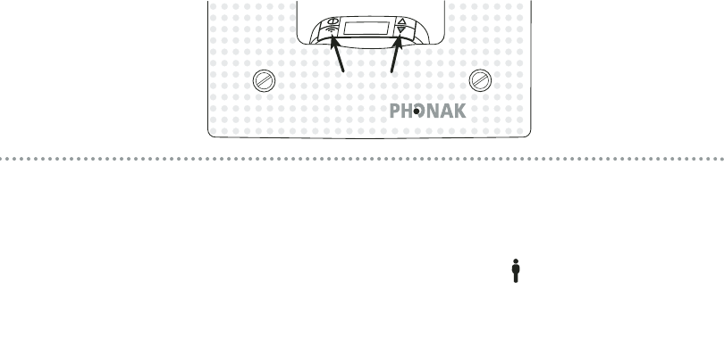
Selecting the channel
10
As with the Campus S, a pair of channel selection buttons sets the FM channel.
Press one of the channel selection buttons for 2 seconds
▲= selects a higher channel ▼= selects a lower channel
☞Ensure that the WallPilot is set to the designated channel for the room. This should
correspond to the channel used by the FM transmitter (e.g. the Campus S) operating
in the same room.
GA 029-0171-02 GB Englisch
11
Adjusting the range
BA
Rotary control on the side of the main unit.
Range switch
F1 = Close range
F2 = Medium range
F3 = Long range
Re-check the range after WallPilot installation and readjust if necessary.
☞It is recommended to check the range regularly.
A
B
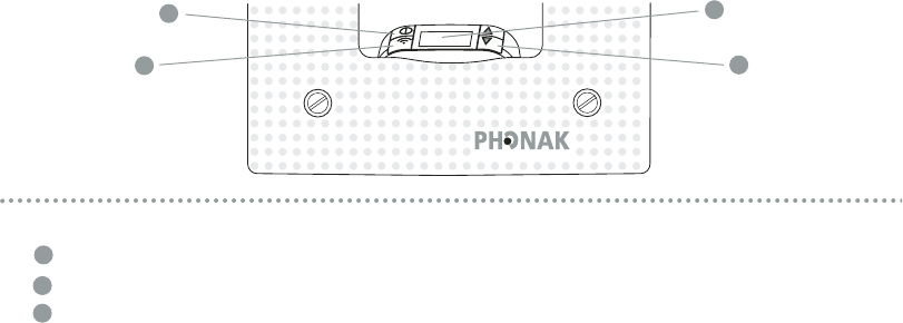
12
The WallPilot has a built-in key lock. Similar to mobile telephones, it avoids uninten-
tionally operating the keys. When activated, the key lock also prevents tampering by
children.
To lock keys: Press both keys simultaneously for 2 seconds. A « »-symbol appears
in the LCD display.
To unlock keys: Press the same keys simultaneously for 2 seconds.
Key lock
GA 029-0171-02 GB Englisch
13
Putting into operation:
Switch on the WallPilot (press the On/Off button for 2 seconds)
Check the channel and battery charge state on the LCD
Activate the key lock if needed (see page 12 key lock)
3
2
1
2
3
1
3
Daily use
14
When FM users enter the room:
The multi-frequency FM user’s receivers are set automatically to the channel selected
in the WallPilot.
Depending on how the multi-frequency MicroLink receivers are programmed, a brief
signal in the hearing instrument may indicate the change of channel.
Switching off:
• Switch off the WallPilot (press the On/Off button for 2 seconds)
If the WallPilot is operated with the rechargeable battery, simply plugging in the power
cord recharges the battery. The three battery segments in the LCD display blink to indi-
cate charging.
GA 029-0171-02 GB Englisch
15
Important notes
1. The hearing instrument and FM receiver must be switched on before the WallPilot
can change the receiver channel.
2. Ensure that the WallPilot is properly fixed and that the power cord is safely secured.
3. Avoid simultaneous use of multiple WallPilots with overlapping transmission ranges.
4. External influences such as interference from computer monitors can reduce the
WallPilot’s operating range.

Phonak distributors worldwide
Group companies: (detailed information on www.phonak.com)
Australia Phonak Australasia Pty. Ltd., Baulkham Hills N. S. W. 2153
Austria Hansaton Akustische Geräte GmbH, 5020 Salzburg
Belgium Lapperre N.V., 1702 Groot-Bijgaarden
Canada Phonak Canada Limited, Mississauga, Ontario L5S 1V9
Denmark Phonak Danmark A/S, Nitivej 10, 2000 Frederiksberg
France Phonak France SA, 69500 Bron
Germany Phonak GmbH, 70736 Fellbach-Oeffingen
Italy Phonak Italia S.r.l., 20159 Milano
Japan Phonak Japan Co., Ltd., Tokyo 101-0044
Jordan Phonak Middle East, 11181 Amman
Netherlands Phonak B.V., 3439 ME Nieuwegein
New Zealand Phonak New Zealand Ltd., Takapuna, Auckland 9
Norway Phonak AS, 0105 Oslo
Spain Phonak Laem S.A., 03008 Alicante
Sweden Phonak AB,117 34 Stockholm
Switzerland Phonak AG, Phonak Schweiz, 8712 Stäfa
United Kingdom Phonak UK Limited, Warrington, Cheshire WA1 1PP
USA Phonak Inc., Warrenville, IL 60555-3927
Independent A complete list of Phonak distributors is available at Phonak's Internet site:
general agents: www.phonak.com. Please visit us or ask your hearingcare professional
for information.
Manufacturer: Phonak AG, Laubisrütistrasse 28, CH-8712 Stäfa, Switzerland

GA 029-0171-02 GB Englisch
Notes

Notes

Service and Warranty
Phonak offers you a comprehensive global warranty which becomes effective on the
date of purchase. Please ask your hearingcare professional for details and duration. This
warranty covers any repairs due to defects in material and/or workmanship. The warranty
does not cover damage from improper handling or care, exposure to chemicals, immer-
sion in water or undue stress. Damage caused by third parties or non-authorized service
centers renders the Phonak warranty null and void. This warranty does not include any
services performed by a hearingcare professional in their office. This warranty applies to
the Phonak products listed below:
Serial number: Date of purchase:
Your hearingcare professional:
029-0171-02/V00 0204 Printed in Switzerland © Phonak AG All rights reserved