Sony Group ANM1000 Low Power Communication Device Transmitter User Manual CAV M1000ES
Sony Corporation Low Power Communication Device Transmitter CAV M1000ES
UserManual.wiki
>
Sony Group
>
ANM1000 User Manual
Users Manual
Navigation menu
Upload a User Manual
Namespaces
Wiki Guide
HTML
PDF
Info
Views
User Manual
Discussion / Help
Navigation

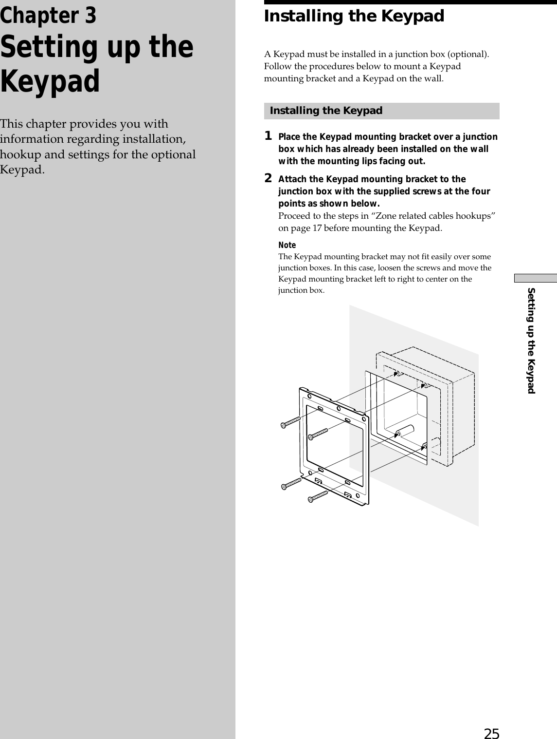
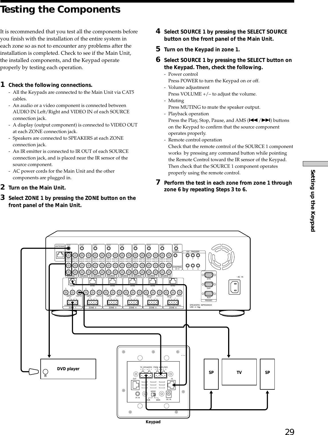
![23Setting up the Main UnitAdjusting the source input offset– SOURCE INPUT OFFSETYou can specify the maximum volume level to optimizethe acoustic conditions in each zone.1Turn off the power.2Press and hold ZONE + and ALL ZONE MUTINGsimultaneously, and then turn on the power.“SOURCE OFFSET” appears in the display windowfor a few seconds.3Press the R cursor or r cursor repeatedly to select asource number.Each time you press the R cursor or r cursor, thedisplay window changes cyclically as shown below.SOURCE OFFSET (Appears for a few seconds)rtSOURCE 1 R rYSOURCE 2 R rtSOURCE 8 R r4Press ENTER.The display window displays the OFFSET settings.5Press the R cursor or r cursor to adjust the offset.Each time you press the R cursor or r cursor, thedisplay window changes cyclically as shown below.tOFFSET 0dB R rOFFSET -1dB R rOFFSET -2dB R rOFFSET -3dB R rOFFSET -4dB R rtOFFSET -5dB R r6Press ENTER when you want to adjust the offsetfor other source components.The step goes back to step 3.7Press CANCEL when you have finished.The display window returns to the NORMAL mode.NoteIn a zone where SOURCE INPUT OFFSET is ON, the actualvolume level is lower than the displayed volume level.…Locking the settings – SETUP LOCKYou can lock in the settings under which have beenentered into the Main Unit.1Turn off the power.2Press and hold SOURCE SELECT + and BACKsimultaneously, and then turn on the power.“SETUP LOCK” appears for a few seconds, then thedisplay window displays the SETUP LOCK window.3Press the R cursor or r cursor to turn SETUP LOCKon or off.The display window changes as follows:SETUP LOCK (Appears for a few seconds)rLOCK [OFF] R rLOCK [ON] R r4Press ENTER when you have finished.The display window returns to the NORMAL mode.Notes•The following are the preferences that can be locked in inthe SETUP LOCK mode.- All settings in the LEARN mode.- All settings in the SETUP mode.- Settings for the Disc Search.- The adjustment of SOURCE OFFSET.- All Clear.•When you select settings that cannot be changed,“LOCKED!” appears for a few seconds, then the displaywindow returns to the NORMAL mode.](https://usermanual.wiki/Sony-Group/ANM1000/User-Guide-406894-Page-23.png)
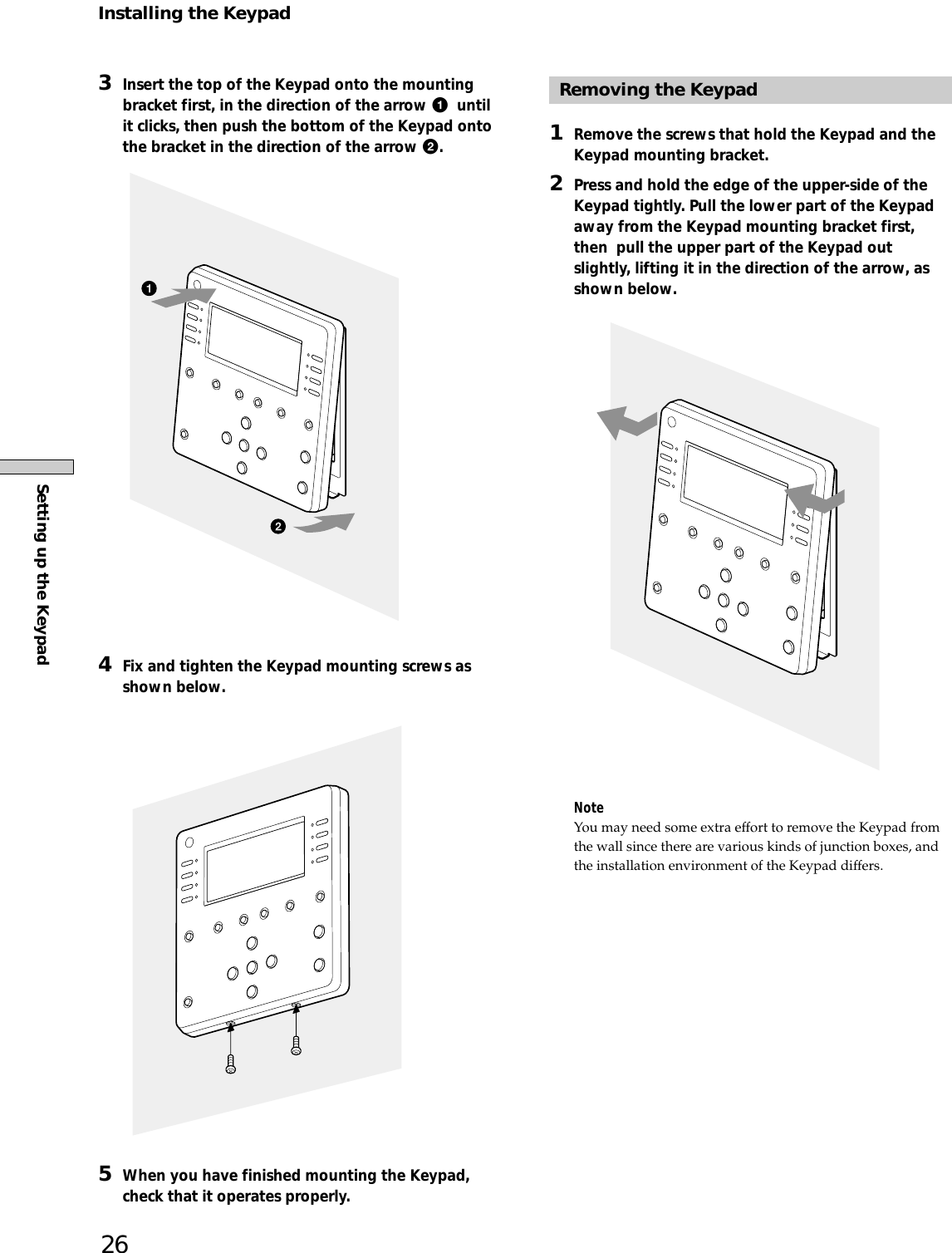
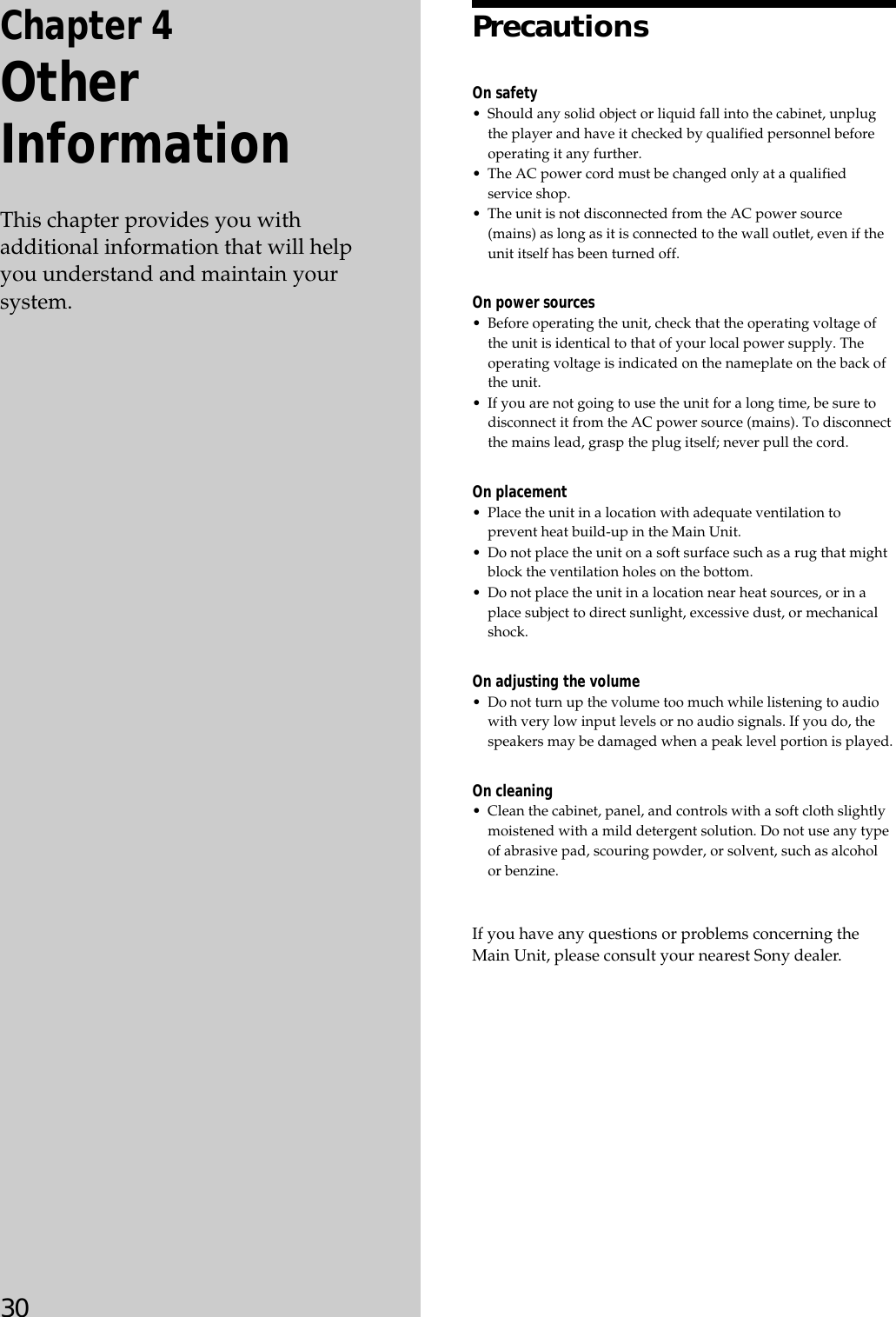
![24Setting up the Main UnitViewing the version information– CIS VERSIONCIS VERSION provides you the version information ofthe Main Unit and other external components, such as anFM/AM Receiver (STR), a DVD Mega Changer, an RFRemote Control, or the Keypad.1Turn off the power.1Press and hold ZONE – and CANCEL simultaneously,and then turn on the power.“CIS VERSION” appears in the display window for afew seconds.2Press the cursor R or r to view the versioninformation.Each time you press the button, the display windowchanges as shown below.CIS VERSION (Appears for a few seconds)rVERSION [X.XX]: displays the version informationof the Main Unit.YSTR [X.XX]: displays the version informationof the FM/AM RECEIVER (STR).YDVD SYS. [X.XX]: displays the version informationof the DVD MEGA CHANGER(system control).YDVD IF. [X.XX]: displays the version informationof the DVD MEGA CHANGER (interface control).YRF RM [X.XX]: displays the version informationof the RF Remote Control.YKEYPAD [X.XX]: displays the version informationof the Keypad.rNORMAL modeInitializing all the settings – ALL CLEARNote that all memory data will be deleted when youinitiate an ALL CLEAR setting.1Turn off the power.2Press and hold SOURCE SELECT + and CANCELsimultaneously, and then turn on the power.“MEMORY CLEARING” appears in the displaywindow during the initialization.When the initialization is completed, “MEMORYCLEARED!” appears for four seconds, then thedisplay window returns to the NORMAL mode.3Power will be turned off automatically after thedisplay window returns to the NORMAL mode.Notes•Any command keys other than POWER are not enabled duringthe initialization of the Main Unit. If pressed, they are notrecognized.•If you turn off the power before the initialization is completed,the Main Unit will start initializing settings again when youturn on the power the next time.Customizing the Main Unit – INSTALLATION Mode](https://usermanual.wiki/Sony-Group/ANM1000/User-Guide-406894-Page-24.png)